
Manual


.
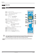
4 Electrical connections
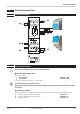
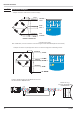
4.1 Connecting diagram
4.2
Terminal connections
a
Faulty connection might cause destruction of the instrument !
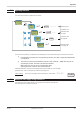
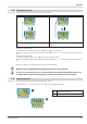
1 Connecting the supply voltage
Dependent on order
•
90 … 260 V AC terminals: 15,16
•
24 V AC / DC terminals: 15,16
For further information, see section "Technical data"
g
Instruments with optional system interface:
Energization is via the bus connector of field bus coupler or power supply module. Terminals 15, 16 must
not be used.
2 Connecting input INP1
Input for strain gauge (in 4 and 6-wire connection) or for melt pressure sensors (with/without calibration shunt).
a Excitation voltage for bridge (EXITATION ) terminals: 1, 4
b Excitation voltage measuring signal (Sense) terminals: 2, 3
c Bridge signal (input) terminals: 5, 6
Electrical connections
SG 45 Connecting diagram 11
Data A
Data A
Data B
Data B
OUT3
PWR
OUT1
OUT2
di1
RGND
RGND
RS 485
1
INP1
2
3
4
5
6
a
c
b
d
e
11 12 13 14
11 12 13 14
15 16 17 18
15 16 17 18
1234
1234
top
14
13
12
16
15
11
17
18
L
N
~90-260V
~24V
V
16
15
17
18
System
8
76
3
2
1
5
3
4
INP
+
-
EX +
EX -
+ Sense -
R-CAL