PMA Prozeß- und Maschinen-Automation GmbH Transmitter UNIFLEX SG45 + INP EX+ +SENSE- EX- kg UNIFLEX SG 45 2 UNIFLEX SG 45 SG Operating manual English 9499-040-82311 valid from: 10/2009
û BlueControlÒ More efficiency in engineering, more overview in operating: â The projecting environment for the BluePort controllers, indicators and rail line - measuring converters / universal controllers, temperature limiters ! es on N IO pdat de T N d U ine. E T n an onl CD T A rsio ma- A- M Ve w.
Content 1. General . . . . . . . . . . . . . . . . . . . . . . . . . . . . . . . . . . . . . . . . . . . . 5 2. Safety hints . . . . . . . . . . . . . . . . . . . . . . 2.1 MAINTENANCE, REPAIR AND MODIFICATION 2.2 Cleaning . . . . . . . . . . . . . . . . . . . . . 2.3 Spare parts . . . . . . . . . . . . . . . . . . . . . . . . . . . . . . . . . . . . . . . . . . . . . . . . . . . . . . . . . . . . . . . . . . . . . . . . . . . . . . . . . . . . . . . . . . . . . . . .7 .8 .8 .8 3.
7. Configuration level. . . . . . . . 7.1 Configuration survey . . . 7.2 Adjustment: . . . . . . . . . 7.3 Configurations . . . . . . . . . . . . . . . . . . . . . . . . . . . . . . . . . . . . . . . . . . . . . . . . . . . . . . . . . . . . . . . . . . . . . . . . . . . . . . . . . . . . . . . . . . . . . . . . . . . . . . . . . . . . . . . . . . . . . . . . . 34 . 34 . 34 . 35 8. Parameter-level . . . 8.1 Parameter-survey 8.2 Adjustment: . . . 8.3 Parameters . . . . . . . .
General . 1 General Thank you very much for buying a transmitter for load cells, strain gauges, and melt pressure sensors UNIFLEX SG 45 . The UNIFLEX SG 45 transmitters are suitable for precise, cost-efficient contol tasks in all industrial applications. Every SG 45 is equipped with a strain gauge signal input, an universal output and two relays. Optionally the tranmitter can be fitted with various interfaces.
General 6 SG 45
Safety hints . 2 Safety hints This unit was built and tested in compliance with VDE 0411-1 / EN 61010-1 and was delivered in safe condition. The unit complies with European guideline 89/336/EWG (EMC) and is provided with CE marking. The unit was tested before delivery and has passed the tests required by the test schedule.
Safety hints 2.1 MAINTENANCE, REPAIR AND MODIFICATION The units do not need particular maintenance. There are no operable elements inside the device, so the user must not open the unit Modification, maintenance and repair work may be done only by trained and authorized personnel. For this purpose, the PMA service should be contacted. a l g Warning When opening the units, or when removing covers or components, live parts and terminals may be exposed. Connecting points can also carry voltage.
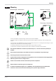
Mounting . 3 Mounting 4 3 2 6 7 K 8 te lem rm m in e / 1 al 5 Montage / mounting 5.5 (0,20”) Abmessungen / dimensions 2.3 (0,08”) 15 14 13 Demontage / dismantling 12 16 17 K 1 te lem 8 rm m in e / a 11 l 99 (3,90”) click 111 (4,37”) 22.5 (0,87”) 117.5 (4,63”) max. 55°C min. -10°C max. 95% rel. % 1 The unit is provided for vertical mounting on 35 mm top-hat rails to EN 50022. If possible, the place of installation should be exempt of vibration, aggressive media (e.g.
Mounting 3.1 Connectors The four instrument connectors are of the plug-in type. They plug into the housing from top or bottom and click in posi tion (audible latching). Releasing the connectors should be done by means of a screwdriver. Two connector types are available: 2 • Screw terminals for max. 2,5 mm conductors 2 • Spring-clamp terminals for max. 2,5 mm conductors g Before handling the connectors, the unit must be disconnected from the supply voltage.
Electrical connections . 4 Electrical connections 4.1 Connecting diagram c 2 a INP1 b INP + 5 6 EX + 1 7 + Sense - 3 2 8 3 di1 1234 EX - 4 R-CAL top RGND RGND Data A Data B Data A Data B RS 485 6 d e 5 1 V OUT3 11 12 PWR 15 16 17 18 13 14 L N ~90-260V ~24V 15 OUT1 OUT2 4 11 12 13 14 15 16 17 18 16 17 18 System 4.
Electrical connections 3 Connecting input di1 Digital input control input (as a potentialfree contact) terminals: 7, 8 4 Connecting outputs OUT1 / OUT2 (optional) Relay outputs max. 250V/2A NO contacts with a common terminal. • OUT1 • OUT2 terminals: 17, 18 terminals: 17, 14 5 Connecting output OUT3 Universal output d current (0...20mA) e voltage (0...
Electrical connections 4.3 Connecting diagram The instrument terminals used for the engineering can be displayed and printed out via BlueControl Ò ( menu File \ Print preview - Connection diagram). Example: Device1.bct Connecting plan Terminal connector 1 Name Description Sensor supply Probe cable Process value X1 Terminal connector 2 Name Description 0...
Electrical connections 4.
Electrical connections 4.5 Hints for installation w w w w w a a a Measurement and data lines should be kept separate from control and power supply cables. Sensor measuring cables should be twisted and screened, with the screening connected to earth. External contactors, relays, motors, etc. must be fitted with RC snubber circuits to manufacturer specifications. The unit must not be installed near strong electric and magnetic fields.
Electrical connections 16 UL approval (optional) SG 45
Operation . 5 Operation 5.1 Front view 1 Line 1: process value display 2 Line 2: display of unit / extended operating level / error list / Conf and PArA level values 3 Tare / sample & hold activated 4 Error list (2 x ô ), e.g. · Fbf. x sensor fault INP. X · Pol. x wrong polarity INP. X · Lim. x limit value alarm · ...
Operation 5.2 Operating structure The instrument operation is divided into four levels: 450.3 KG äüüü 1 2 F E 3s ô 450.3 ô InSt äüüü 1 2 F PASS Operating level E ô 450.3 PARA äüüü 1 2 F PASS Installation and Calibrating level See page E 450.3 CONF äüüü 1 2 F ô PASS Parameter level See page 45 E 450.
Operation 5.4 Displays in the operating level 5.4.1 Display line 1 The display value is the value resulting from function.1, function.2, function.3 handling. It is also called process value (see also section/page 23.) 5.4.2 Display line 2 The value to be displayed continuously in the second LCD line can be selected from different values via the BlueControlÒ engineering tool. As default, the adjusted engineering unit is displayed. 1 2 450.3 450.
Operation 5.4.4 Slave pointer function The minimum and maximum input values are stored in the unit. 450.3 450.3 ûC äüüü 1 2 F ûC äüüü E 1 2 F min E max 450.3 450.3 26.7 äüüü 1 2 F 502.4 äüüü E 1 2 F E The minimum input value is displayed as long as key Ì is The maximum input value is displayed as long as key È pressed. is pressed. Deleting the minimum value The minimum value is deleted by pressing key È whilst key Ì is kept pressed.
Operation 5.4.6 Extended operating level The operation of important or frequently used parameters and signals can be allocated to the extended operating level. This facilitates the access, e.g. travelling through long menu trees is omitted, or only selected values are operable, the other data of the parameter level are e.g. disabled. Display of the max. 8 available values of the extended operating level is in the second LCD line.
Operation SG 45 Displays in the operating level 22
Functions . 6 Functions The signal data flow of transmitter SG 45 is shown in the following diagram: 6.1 Measuring input INP Measuring range 0.5 mV/V (5 mV) 1 mV/V (10 mV) 2 mV/V (20 mV) 4 mV/V (40 mV) Configuration S.
Functions 6.2 Input scaling Scaling of input values is possible. This correction influences the measured value after an eventually executed linearization. g Specification of the input value of the lower and upper scaling point is in units of the relevant physical quantity. phys. quantity OuH.x phys. quantity mA / V OuL.x InH.x mA/V InL.x Example for % g The Parameters InL, OuL, InH and OuH are always visible. These are created during calibration. Parameters InL and InH determine the input range.
Functions 6.3 Linearization The input values of the input can be linearized via a table. This feature can be used e.g. to realize linearizations to specification for non-linear curves. The “ Lin” table is always used when S.Lin = 1: “Linearization to specification” is set in INPm. The input signals are filled in in units of the physical quantity (scaling result). Non-linear signals can be linearized using up to 32 segment points. Each segment point comprises an input ( In.1 … In.32) and an output (Ou.
Functions 6.4 Filter A 1st order mathematical filter with adjustable time constant and bandwidth is built in. x Output Input b.F t The filter bandwidth b.F1 is the adjustable tolerance around the measured value within which the filter is active. Measurement value changes in excess of the adjusted bandwidth are not filtered. 6.
Functions 6.7 Set zero The function is enabled during configuration (Func r Func.1 =1. Due to its effect, the display is reset to zero, when e.g. small rest quantities are still on the scale and cannot be re moved immediately. To prevent excessive use of the zero setting function, the zero offset (page 30) can be provided with an alarm. After cleaning the scale, zero setting must be repeated.
Functions 6.10 Integrator function The input signal can be totalized by means of a selectable integrator (ConF \ Func \ Fnc.3 = 3). Function: Integrator with adjustable time constant (PArA \ Func \ t.I) [specified in minutes] and adjustable input offset (PArA \ Func \ P.I) Formula: y(t) = y(t-Tr) + Tr/t * (x +P.I) y(t) = integrator output y(t-Tr) = integrator output of the last cycle Tr = cycle time (100ms INP1, 140ms INP1 + INP2) t = time constant x = integrator input P.
Functions 6.11 Limit value processing Max. three limit values can be configured for the outputs. Generally, each one of outputs Out.1... Out.2 can be used for limit value or alarm signalling. Several signals allocated to an output are linked by a logic OR function. 6.11.1 Input value monitoring g The signal to be monitored can be selected separately for each alarm in the configuration.
Functions Alarm delay An alarm can become effective with a delay: the alarm output is set only after elapse of the adjusted delay time, provided that the limit value is still exceeded. Shorter alarms than the adjusted delay are ignored. Example: Alarm delay Signal change monitoring Another limit value processing function is signal change monitoring (per minute). Behaviour with signal change (Ex. Lim1) L.1 = OFF x {x {t >H.1 {x {t >H.1 t [min] Lim.
Functions g With measurement value or signal change with latch selected ( ConF / Lim / Fnc.x = 2, 4), the alarm relay remains set, until it was reset in the error list, This alarm can be reset via: di1 or a limit value a key combination or via interface (Lim1 ... Lim3 = 1). For this, reset value 0 must be specified in the error list or via the interface. ( r page 36). H.1 = OFF x {x {t
Functions 6.11.2 Monitoring the number of operating hours and switching cycles Operating hours The number of operating hours can be monitored. When reaching or exceeding the adjusted value, signal InF.1 is acti vated (in the error list and via an output, if configured). The monitoring timer starts when setting limit value C.Std. Reset of signal InF.1 in the error list will start a new moni toring timer. Monitoring can be stopped by switching off limit value C.Std.
Functions 6.12 Analog output configuration 6.12.1 Analog output The two output signals (current and voltage) are available simultaneously. Adjust ConF / Out.3 / O.tYP to select the output type which should be calibrated. ConF / Out.3: O.tYP = = = = 1 2 3 4 Out.3 Out.3 Out.3 Out.3 0...20mA continuous 4...20mA continuous 0...10V continuous 2...10V continuous phys. size Out.1 mA / V phys. size Out.0 0/4mA 0/2V 20mA 10V Parameter O.Src defines the signal source of the output value. Example: O.
Functions 6.12.2 Analog output forcing By adjusting f.Out = 1 (only via BlueControl Ò), the output can be configured for value input via interface, or by means of an input value at extended operating level (=Forcing). g g SG 45 This setting can be used also for e.g. testing the cables and units connected in the output circuit. This function can also realize a setpoint potentiometer.
Functions 6.13 Maintenance manager / error list In case of one or several errors, the error list is always displayed at the beginning of the extended operating level . A current input in the error list (alarm or error) is always indicated by display of letter E . For display of the error list, press key ô once. 450.
Functions g Latched alarms Lim1/2/3 (E-element displayed) can be acknowledged, i.e. reset via digital alarm di1. For Configuration, see page 41: ConF / LOGI / Err.r g When an alarm is still pending, i.e. unless the error cause was removed ( E display blinks), latched alarms cannot be acknowledged and reset.
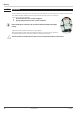
Functions 6.15 Resetting to factory setting In case of faulty configuration, the SG 45 can be reset to the default manufacturers condition. 1 1 For this, the operator must keep the keys increment and + Power on switch on power supply FAC decrement pressed during power-on. torY 2 Then, press key increment to select YES. 3 Confirm factory resetting with Enter and the copy FAC procedure is started (display COPY). no 4 Afterwards the device restarts.
Configuration level . 7 Configuration level 7.1 Configuration survey Dependent on the device version and further adjusted configurations, configurationdata can be hidden. The data which can be operated via the front panel are shown below. st st st st st st st st Lim OUt. 1 OUt.2 OUt.3 LOGI othr End Func Inp.1 ô ô ô Fnc.1 StYP Fnc.1 Fnc.2 S.Lin Src.1 Fnc.3 In.F Fnc.2 ô Src.2 ô ô ô ô 0.Act 0.Act O.tYP Lim.1 Lim.1 Out.0 Lim.2 Lim.2 Out.1 Lim.3 Lim.3 O.src ô ô di.Fn S.If L_r Addr Err.
Configuration level 7.3 Configurations Dependent on device version und adjusted configurations values not needed become hidden. µ Entrys marked with this symbol are selectable only with existing device-option. Selection of functions Func Name Value range Fnc1 0 1 Fnc.2 0 3 Fnc.3 0 2 3 Description Function 1 No function Zero setting Function 2 No function Tare Function 3 No function Sample & Hold Integrator Input INP Name Value range S.tYp 60 61 62 63 S.Lin 0 1 In.
Configuration level Outputs Out.1 and Out.2 (relay) Name O.Act Lim.1 Lim.2 Lim.3 FAi.1 Sb.Er Inf.1 Inf.
Configuration level Signal definition LOGI Name Value range di.Fn 0 1 2 L_r 0 1 2 7 8 9 Err.r 0 2 7 8 9 10 11 tArA 0 2 7 8 9 10 11 HoLd 0 2 7 8 9 10 11 rES.
Configuration level Name Value range rES.H 0 2 7 8 9 10 11 rES.I 0 2 7 8 9 10 11 CAL.
Configuration level Miscellaneous (other) Name Value range S.IF Addr bAud 0 1 1...247 0 1 2 3 4 PrtY dELY FrEq 0 1 2 3 0...200 0 1 D.Unt 0 3 4 5 6 7 8 18 19 20 21 22 23 24 25 dP 0 1 2 3 CAL.M C.dEl 0 1 0..
Configuration level Name ILat Value range Pass IPar 0 1 OFF...9999 0 1 ICnf 0 1 IInst 0 1 T.Dis2 Description Ò Block error memory (only visible with BlueControl !) Released Blocked Ò Password (only visible with BlueControl !) Ò Block parameter level (only visible with BlueControl !) Released Blocked Ò Block configuration level (only visible with BlueControl !) Released Blocked Ò Block installation level (only visible with BlueControl !) Released Blocked Settings for text in display 2 (max.
Parameter-level . 8 Parameter-level 8.1 Parameter-survey Dependent on device version und adjusted configurations values not needed become hidden. The data which can be operated via the front panel are shown below. 8.2 Adjustment: • • • g SG 45 Parameters can be adjusted with ÈÌ - keys. Stepping to the next parameter by pressing the ô - key. After the last parameter of a group donE appears in the display and the controller steps automatically to the next group.
Parameter-level 8.3 Parameters Selection of functions Func Name t.I P.I Value range 0,1...9999 -1999...9999 Description Integrator timeconstant (in minutes) Integrator-Offset Inputs InP.1 Name InL.1 Oul.1 InH.1 OuH.1 t.F1 b.F1 Value range -1999...9999 -1999...9999 -1999...9999 -1999...9999 0...999.9 0...9999 Description Lower input value (Span start) Lower output value Upper input value (Span end) Upper output value Filter time [s] Filterbandwidth Limit values Lim1 … Lim 3 Name L.1 H.1 HYS.1 dEL.
Installation and calibration . 9 Installation and calibration When the operating voltage is applied to SG45 after connecting e.g. the load cells, the unit starts running. An automatic check for connection of the Sense lines takes place. This check is done also after configuration changes. For installation, press ô during 3 sec to change over to installation mode InSt . Select SEt ô and adjust S.typ (cell type) to select calibrating method CAL.M. 3s 45.6 InSt SEt CAL SCAL S.tyP InL.1 InL.1 CAL.
Installation and calibration 9.2 Calibration ( CAL) + Before calibration, allow the unit to warm up (see Technical Data on page 54). After delivery, a % value is displayed as a measured value (related to the adjusted measuring range). For this reason, the Uniflex SG 45 must be adapted to its measuring task accordingly. To adapt the unit, realize the cal ibration correctly. + If necessary, the required display unit (D.Unt) must be selected accordingly.
Installation and calibration 9.3 Scaling (SCAL) · (Menu with SEt – CAL – SCAL – End) q Þ possibility for read out of the scaling determined under CAL or for direct input of scaling parameters InL.1 ¿ OuL.1 ¿ InH.1 ¿ OuH.1 ¿ donE . · End ô · Operating level + Note related to melt pressure sensor Adjust gradient 4mV/V for 3,33mV/V of the sensor. Please note that the InL.1 and InH.1 values are displayed with a resolution of 4 digits.
Engineering Tool BlueControl . 10 Engineering Tool BlueControl Ò Ò The Engineering Tool BlueControl Ò is the projecting environment for the BluePort â controller series as for the rail line family of PMA.
Versions . 11 Versions Transmitter SG 4 5 UNIFLEX SG 45 1 measuring input, 1 digital input with display and BluePort®-interface 0 0 0 without plug-in connector terminals with screw-terminal connectors 00 0 1 90..260V AC, mA/V/logic + 2 relays 18...30VAC/18..
Technical data . 12 OUTPUTS Technical data RELAY OUTPUTS OUT1, OUT2 INPUTS Contact type: SIGNAL INPUT INP Accuracy: Decimal point: Input filter: Scanning cycle: Linearization: Calibration: Measurement value correction: Limiting frequency Measurement value correction: Connection technology: Max. contact rating: 0,01% at 25°C 0 bis 3 decimals adjustable 0.0...999.9 s 50 ms with 19 bit 31 Segments, adaptable with BlueControl® with/without shunt calibration 2-point 1.
Technical data GALVANIC ISOLATION System RS 485 Power BLUEPORT® FRONT INTERFACE Input INP Connection to the controller front via a PC adapter (see ‘Additional Accessories’). The BlueControl ® software enables the KS 45 to be configured, parameters set, and operated. di 1 (contact) BUS INTERFACE (OPTIONAL) Front interface RS 485 Connection via bus connector fitted in the top-hat rail. Screened cables should be used.
Technical data ENVIRONMENTAL CONDITIONS GENERAL Protection mode Housing front Material: Flammability class: Front panel: Housing: Terminals: IP 20 IP 20 IP 20 Permissible temperatures For specified accuracy: Warm-up time: Temperature effect: add. influence to coldjunction compensation: Operating limits: Storage: -10...55°C < 20 minutes ß 0.02 % / 10 K ß 0.05 % / 10 K -20...60°C -30...70°C Humidity Polyamide PA 6.
Index . 13 Index A Accessories . . . . . . . . . . . . . . . . . . . . . . 47 Alarm delay . . . . . . . . . . . . . . . . . . . . . . 28 Analog output . . . . . . . . . . . . . . . . . . 30 - 31 Applications . . . . . . . . . . . . . . . . . . . . . . 5 maximum value . . . . . . . . . . . . . . . . . . . . 19 minimum value . . . . . . . . . . . . . . . . . . . . 19 Mounting . . . . . . . . . . . . . . . . . . . . . 9 - 10 N Number of switching cycles . . . . . . . . . . . . . 29 B BlueControl . . . .
Subject to alterations without notice Änderungen vorbehalten Sous réserve de toutes modifications © PMA Prozeß- und Maschinen-Automation GmbH P.O.B.