ProVU4 Controller, Profiler & Recorder/Controller - Product Manual ProVU4 Graphical Controller with optional Profiling & Recording User Guide Part Number: 59407-1 Price: £12.00 $20.00 €18.
ProVU4 Controller, Profiler & Recorder/Controller - Product Manual This manual supplements the Concise Product manual(s) supplied with each instrument at the time of shipment. Information in this installation, wiring and operation manual is subject to change without notice. Copyright © March 2008, Danaher Corporation, all rights reserved.
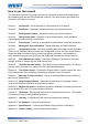
ProVU4 Controller, Profiler & Recorder/Controller - Product Manual Warranty and Returns Statement These products are sold by West Instruments under the warranties set forth in the following paragraphs. Such warranties are extended only with respect to a purchase of these products, as new merchandise, directly from West Instruments or from a West Instruments distributor, representative or reseller and are extended only to the first buyer thereof who purchases them other than for the purpose of resale.
ProVU4 Controller, Profiler & Recorder/Controller - Product Manual How to use this manual This manual is structured to give easy access to the information required for all aspects of the installation and use and of the Graphical Controller. The main sections are shown here, followed by a full table of contents. Section 1: Introduction - A brief description of the product and it’s features. Section 2: Installation - Unpacking, installing and panel mounting instructions.
ProVU4 Controller, Profiler & Recorder/Controller - Product Manual Contents Page Number: Warranty and Returns Statement .................................................................................................... iv 1 Introduction .......................................................................................................................... 14 2 Installation ............................................................................................................................
ProVU4 Controller, Profiler & Recorder/Controller - Product Manual Start-up Errors.....................................................................................................................................39 Input Problems ....................................................................................................................................39 USB Data Transfer Problems...............................................................................................................
ProVU4 Controller, Profiler & Recorder/Controller - Product Manual USB Memory Stick Folders & Files .................................................................................................64 9 The Data Recorder Option ................................................................................................... 65 Introduction .........................................................................................................................................65 Changes To Operation Mode.
ProVU4 Controller, Profiler & Recorder/Controller - Product Manual Profile Setup Over Modbus ................................................................................................................113 Instrument Data .................................................................................................................................128 14 Calibration...........................................................................................................................
ProVU4 Controller, Profiler & Recorder/Controller - Product Manual Current Proportioning Control ............................................................................................................139 Custom Display Mode........................................................................................................................139 Cycle Time ........................................................................................................................................
ProVU4 Controller, Profiler & Recorder/Controller - Product Manual On-Off Control ...................................................................................................................................147 On-Off Differential (On-Off Hysteresis)...............................................................................................147 Operation Mode.................................................................................................................................
ProVU4 Controller, Profiler & Recorder/Controller - Product Manual Secondary Proportional Band ............................................................................................................156 Self-Tune...........................................................................................................................................157 Sensor Break Pre-Set Power .............................................................................................................
ProVU4 Controller, Profiler & Recorder/Controller - Product Manual Auxiliary Inputs ..................................................................................................................................173 Digital Inputs......................................................................................................................................174 Output Specifications........................................................................................................................
ProVU4 Controller, Profiler & Recorder/Controller - Product Manual 1 Introduction This product is a 1/4 DIN size (96 x 96mm front) microprocessor based graphical process controller, featuring a 160 x 80 pixel, monochrome LCD with a dual colour (red/green) backlight. It can control process variables from a variety of sources such as temperature, pressure, flow and level. The operating voltage is either 100-240V at 50/60 Hz or 24V-48V AC/DC depending on the model purchased.
ProVU4 Controller, Profiler & Recorder/Controller - Product Manual 2 Installation Unpacking 1. Remove the product from its packing. Retain the packing for future use, in case it is necessary to transport the instrument to a different site or to return it to the supplier for repair/testing. 2. The instrument is supplied with a panel gasket and push fit fixing strap. A single sheet concise manual is also supplied in one or more languages. Examine the delivered items for damage or defects.
ProVU4 Controller, Profiler & Recorder/Controller - Product Manual Instruments may be mounted side-by-side in a multiple installation, but instrument to panel moisture and dust sealing will be compromised. Allow a 20mm gap above, below and behind the instrument for ventilation. The cut-out width (for n instruments) is: (96n - 4) mm or (3.78n - 0.16) inches If panel sealing must be maintained, mount each instrument into an individual cut-out with 6mm or more clearance between the edges of the holes.
ProVU4 Controller, Profiler & Recorder/Controller - Product Manual 3 -Field Upgrade Options Options Modules and Functions The available plug-in modules, options and accessories are shown in below: Table 1.
ProVU4 Controller, Profiler & Recorder/Controller - Product Manual Board Positions Board Mounting Struts Option 4 Module Option A Module Option 3 Module Universal Input Board Power Supply Board Option B Module Option 1 Module (hidden below B) Option 2 Module Option C Module Figure 3. Rear view (uncased) & board positions Preparing to Install or Remove Options Modules CAUTION: Before removing the instrument from it’s housing, ensure that all power has been removed from the rear terminals.
ProVU4 Controller, Profiler & Recorder/Controller - Product Manual Main Board Connectors POWER SUPPLY BOARD Transformer Colour Code Option 3 Slot Connector PL4B Option Slot A Connectors PL5, & PL6 100-240V (Yellow) 24-48V(Blue) Option 1 Slot Connectors PL7 & PL8 Display Board Connections PC Configurator Socket SK1 Option 2 Slot Connector PL4A UNIVERSAL INPUT BOARD Option Slot B Connectors PL2A, PL2B & PL2C Figure 4. Main board connectors Removing/Replacing Option Modules 1.
ProVU4 Controller, Profiler & Recorder/Controller - Product Manual Replacing the Instrument in its Housing CAUTION: Before replacing the instrument in it’s housing, ensure that all power has been removed from the rear terminals. With the required option modules correctly located into their respective positions the instrument can be replaced into it’s housing as follows: 1. Hold the Power Supply and Input boards together. 2. Align the boards with the guides in the housing. 3.
ProVU4 Controller, Profiler & Recorder/Controller - Product Manual Data Recorder Board If installed, the Data Recorder memory and Real Time Clock (RTC) components are located on a plug-in daughter board attached to the front Display/CPU board. CAUTION: Servicing of the Data Recorder/RTC circuit and replacement of the lithium battery should only be carried out by a trained technician.
ProVU4 Controller, Profiler & Recorder/Controller - Product Manual 4 Electrical Installation CAUTION: Installation should be only performed by technically competent personnel. It is the responsibility of the installing engineer to ensure that the configuration is safe. Local Regulations regarding electrical installation & safety must be observed (e.g. US National Electrical Code (NEC) or Canadian Electrical Code).
ProVU4 Controller, Profiler & Recorder/Controller - Product Manual Use of Shielded Cable All analogue signals must use shielded cable. This will help eliminate electrical noise induction on the wires. Connection lead length must be kept as short as possible keeping the wires protected by the shielding. The shield should be grounded at one end only. The preferred grounding location is at the sensor, transmitter or transducer.
ProVU4 Controller, Profiler & Recorder/Controller - Product Manual Sensor Placement (Thermocouple or RTD) If the temperature probe is to be subjected to corrosive or abrasive conditions, it must be protected by an appropriate thermowell. The probe must be positioned to reflect true process temperature: 1. In a liquid media - the most agitated area 2.
ProVU4 Controller, Profiler & Recorder/Controller - Product Manual Connections and Wiring This symbol means the equipment is protected throughout by double insulation. CAUTION: All external circuits connected must provide double insulation. Failure to comply with the installation instructions may impact the protection provided by the unit. WARNING: TO AVOID ELECTRICAL SHOCK, AC POWER WIRING MUST NOT BE CONNECTED TO THE SOURCE DISTRIBUTION PANEL UNTIL ALL WIRING PROCEDURES ARE COMPLETED.
ProVU4 Controller, Profiler & Recorder/Controller - Product Manual The wiring diagram below shows the additional connections (numbered 25 to 42) at the sides of the case rear. These are required for Options Slots 4 and C if fitted. Figure 8. Additional Option terminals Note: Use single strand (1.2mm / AWG18 max size) copper wire throughout, except for the thermocouple input, where the correct thermocouple or compensating cable and connectors must be used.
ProVU4 Controller, Profiler & Recorder/Controller - Product Manual Power Connections - 24/48V AC/DC Powered Instruments 24/48V AD/DC powered instruments will operate from a 20 to 48V AC or 22 to 55V DC supply. AC power consumption is 15VA max, DC power consumption is 12 watts max. Connection should be via a two-pole IEC60947-1 & IEC60947-3 compliant isolation switch / circuit breaker and a UL listed fuse type: 65v dc 1Aamp anti-surge. _ 13 14 Figure 10.
ProVU4 Controller, Profiler & Recorder/Controller - Product Manual Universal Input Connections – PT100 / NI120 (RTD) input For three wire RTDs, connect the resistive leg and the common legs of the RTD as illustrated. For a two wire RTD a wire link should be used in place of the third wire (shown by dotted line). Two wire RTDs should only be used when the leads are less than 3 metres long. Avoid cable joints. 3 2 RTD 1 Figure 12.
ProVU4 Controller, Profiler & Recorder/Controller - Product Manual Option Slot 1 Connections Option Slot 1 – Single Relay Output Module If option slot 1 is fitted with a single relay output module, make connections as illustrated. The relay contacts are SPDT and rated at 2 amps resistive, 240 VAC. Figure 14.
ProVU4 Controller, Profiler & Recorder/Controller - Product Manual Option Slot 1 - Linear Voltage or mADC Output module If option slot 1 is fitted with a DC linear output module, make connections as illustrated. _ 19 20 21 Figure 17. + Option Slot 1 - Linear Voltage & mADC Module Option Slot 2 Connections Option Slot 2 – Single Relay Output Module If option slot 2 is fitted with a single relay output module, make connections as illustrated.
ProVU4 Controller, Profiler & Recorder/Controller - Product Manual Option Slot 2 – Single SSR Driver Output Module If option slot 2 is fitted with a single SSR driver output module, make connections as illustrated. The solid-state relay driver is a 0-10V DC signal, load impedance must be no less than 500 ohms. SSR driver outputs are not isolated from the signal input or other SSR driver outputs. _ 22 23 24 Figure 20.
ProVU4 Controller, Profiler & Recorder/Controller - Product Manual Option Slot 2 - Linear Voltage or mADC Output module If option slot 2 is fitted with a DC linear output module, make connections as illustrated. _ 22 23 24 Figure 23. + Option Slot 2 - Linear Voltage & mADC module Option Slot 2 - Transmitter Power Supply Module If option slot 2 is fitted with a transmitter power supply module, make connections as illustrated. The output is an unregulated 24V DC, 22mA supply. _ 22 23 24 Figure 24.
ProVU4 Controller, Profiler & Recorder/Controller - Product Manual Option Slot 3 - Dual Relay Output Module If option slot 3 is fitted with a dual relay output module, make connections as illustrated. This module has two independent SPST relays, which share a common connection terminal. The contacts are rated at 2 amp resistive 240 VAC. 10 N/O OUTPUT 3B 11 COMMON 12 N/O OUTPUT 3A Figure 26.
ProVU4 Controller, Profiler & Recorder/Controller - Product Manual Option Slot 3 – Dual SSR Driver Output Module If option slot 3 is fitted with a dual SSR driver output module, make connections as illustrated. The solid-state relay drivers are a 0-10V DC signal, load impedance must be no less than 500 ohms. SSR driver outputs are not isolated from the signal input or other SSR driver outputs. Figure 28.
ProVU4 Controller, Profiler & Recorder/Controller - Product Manual Option Slot 3 - Transmitter Power Supply Module If option slot 3 is fitted with a transmitter power supply module, make connections as illustrated. The output is an unregulated 24V DC, 22mA supply. _ 10 11 12 Figure 31. + Option Slot 3 - Transmitter Power Supply Module Option Slot A Connections Option Slot A Connections – Basic Auxiliary Input Module If option slot A is fitted with a basic auxiliary input module, connect as shown.
ProVU4 Controller, Profiler & Recorder/Controller - Product Manual Option Slot A Connections - RS485 Serial Communications Module If option slot A is fitted with the RS485 serial communication module, connections are as illustrated. Carefully observe the polarity of the A (Rx/Tx +ve) and B (Rx/Tx -ve) connections. Figure 34.
ProVU4 Controller, Profiler & Recorder/Controller - Product Manual 5 Powering Up CAUTION: Ensure safe wiring practices have been followed. When powering up for the first time, disconnect the output connections. The instrument must be powered from a supply according to the wiring label on the side of the unit. The supply will be either 100 to 240V AC, or 24/48V AC/DC powered. Check carefully the supply voltage and connections before applying power.
ProVU4 Controller, Profiler & Recorder/Controller - Product Manual LED Functions There are four red LEDs that by default, indicate the status of the primary and secondary control outputs, automatic tuning and alarm status. The top line of the graphical display has four labels for LED indicators. The function of these LEDs and their display labels can be changed using the PC configuration software. The information in this manual assumes standard functions for these LEDs.
ProVU4 Controller, Profiler & Recorder/Controller - Product Manual 6 Messages and Error Indications Start-up Errors The following displays are shown when an error detected during the power-up self-test. Option Module Problems The “Option Slot n Error” display is shown when an error detected with the installed option modules - where “n” is the slot number for the fault. Replace the module in slot “n”. If this does not solve the problem, return the instrument for servicing.
ProVU4 Controller, Profiler & Recorder/Controller - Product Manual PV Over-range or Under-range Indication If the measured process variable value is more than 5% above than the Scale Range Upper Limit, its value is replace by the word “HIGH”. If the measured process variable value is more than 5% below than the Scale Range Lower Limit, its value is replace by the word “LOW”.
ProVU4 Controller, Profiler & Recorder/Controller - Product Manual 7 Configuration and Use Operation Mode This is the mode used during normal operation of the instrument. It can be accessed from the Main Menu, and is the usual mode entered at power-up. The available displays are dependent upon the features and options fitted and the way in which it has been configured.
ProVU4 Controller, Profiler & Recorder/Controller - Product Manual Example Profile Operating Screen LED Indicators LED Function Labels Process Value & Setpoint Profile Progress Graph Segment Progress Engineering Units Profile Status ► Run, ▌▌ Held, ■ Stopped Table 4. Operation Mode Screens Operation Mode: After 2 minutes without key activity, the most screens revert to the Base Operating Screen. Screens marked do not revert automatically. They remain displayed until the user navigates away.
ProVU4 Controller, Profiler & Recorder/Controller - Product Manual Operator Profile Control Allows the operator to control the defined profiles. If a profile is running, the choices are: Do Nothing; Abort Profile (end immediately); Jump to Next Segment; Hold Profile or Release Hold. If no profile is running, the choices are: Do Nothing; Run Profile or End Profile Control (returns to standard controller operation). - only shown if enabled in the Profile Control Menu.
ProVU4 Controller, Profiler & Recorder/Controller - Product Manual Press to select the Setpoint Value Display and Adjustment screen Press or to adjust each Local Setpoint to the required value. A Remote Setpoint value cannot be altered from the key pad. Adjusting the Setpoint Ramp Rate The Setpoint Ramp Rate may be adjusted in the range 0.1 to 9999.0 (in display units per hour) and OFF. When the Setpoint Ramp Rate is set to Off, setpoint changes will step immediately to the new value.
ProVU4 Controller, Profiler & Recorder/Controller - Product Manual Main Menu This menu is used to access the various features and configuration menus available in the instrument. The available menus are dependent upon the features and options fitted and the way in which it has been configured Entry into the Main Menu Holding down and pressing from Operation Mode and most other screens will cause the unit to enter the Main.
ProVU4 Controller, Profiler & Recorder/Controller - Product Manual Setup Wizard An easy Setup Wizard runs automatically at first ever power-up or if whenever a Reset To Defaults is carried out. Users can follow the Wizard screens to setup parameters required for typical applications (screens marked w in the Screen Sequence lists are included in the Setup Wizard). A partial Wizard also runs whenever option modules have been changed. The partial wizard, only shows parameters affected by the changes made.
ProVU4 Controller, Profiler & Recorder/Controller - Product Manual Supervisor Mode This mode is only available if it has been configured from the PC software. The software is used to copy up to 50 screens from the Configuration Menus to include in Supervisor Mode. The purpose of Supervisor Mode is to allow certain users access to a lock code protected sub-set of the main configuration parameters without providing them with the higher level Configuration Menu unlock code.
ProVU4 Controller, Profiler & Recorder/Controller - Product Manual Configuration Menu This menu can be used as an alternative to the more limited Setup Wizard when the instrument is configured for the first time, or when further changes are required to the instruments characteristics. Configuration contains a number of sub-menus that allow access to all of the available parameters. The correct settings must be made before attempting to use the instrument in an application.
ProVU4 Controller, Profiler & Recorder/Controller - Product Manual Input Configuration Sub-Menu Table 9. Input Configuration Sub-Menu Screens Input Configuration: Process Variable Input Type w From Thermocouple, RTD and Linear inputs. - see specifications section for full details of input types available. Engineering Units w Select display units from: °C; °F; °K; bar; %; %RH; pH; psi or none. Decimal Point Position w Sets the maximum display resolution to 0; 1; 2 or 3 decimal places.
ProVU4 Controller, Profiler & Recorder/Controller - Product Manual Control Configuration Sub-Menu Table 10. Control Configuration Sub-Menu Screens Control Configuration: Control Enable/Disable Sets the method to enable/disable the control output(s). From: Enabled (always); Disabled (always); Enable/Disable via Digital Input A or B, or Operator Selectable (allows control output(s) to be turned off from Operation Mode). Caution: The instrument is not able to control the process when control is disabled.
ProVU4 Controller, Profiler & Recorder/Controller - Product Manual Secondary On-Off Differential Sets the Secondary On-Off control hysteresis (deadband) from 0.1 to 10.0% of Span (centred about setpoint), when Primary PID with Secondary On-Off control is used. Primary & Secondary On-Off Differential Sets the combined Primary & Secondary On-Off Control hysteresis (deadband) from 0.1 to 10.0% of Span. when Primary On-Off control and Secondary On-Off control is used.
ProVU4 Controller, Profiler & Recorder/Controller - Product Manual Setpoint Ramp Rate The Setpoint Ramp Rate value (1 to 9999 display units per hour or OFF). This ramp is applied at power-up and any setpoint changes. Local Setpoint 1 Value w Sets the value of Local Setpoint 1 between the Setpoint Upper and Lower Limits. Local Setpoint 1 Offset Local Setpoint 2 Value A value added to the Setpoint 1 value (+ve values) or subtracted from it (-ve values).
ProVU4 Controller, Profiler & Recorder/Controller - Product Manual Alarm Configuration Sub-Menu Table 12. Alarm Configuration Sub-Menu Screens Alarm Configuration: Alarm n Type w Sets the type for each of the 5 alarms From: Unused; Process High; Process Low; PV-SP Deviation; Band; Control Loop; Rate Of Signal Change; PV Signal Break; Aux. Input A or B Break. Alarm n Value w Alarm activation point.
ProVU4 Controller, Profiler & Recorder/Controller - Product Manual Recorder Configuration Sub-Menu Table 14. Data Recorder Configuration Sub-Menu Screens Recorder Configuration: No Recorder Warning If the Recorder Configuration menu is entered on an instrument without this option fitted. Recording In Progress Warning If recording in progress when Recorder Configuration entered. – Allows access to the Recording Start/Stop screen only, until the recording is stopped.
ProVU4 Controller, Profiler & Recorder/Controller - Product Manual Clock Configuration Sub-Menu Table 15. Internal Clock Configuration Sub-Menu Screens Clock Configuration: Date Format w Sets the format used for all displayed dates: dd/mm/yyyy (Day / Month / Year) or mm/dd/yyyy (Month / Day / Year). – Recorder versions only. Set Date w Sets the internal clock Date. – Entered in the format defined by Date Format screen. – Recorder versions only.
ProVU4 Controller, Profiler & Recorder/Controller - Product Manual Lock Code View Unlock Codes To prevent unauthorised entry, some menus are protected by a lock code. These screens are indicated by the symbol before their names in the screen list tables. To enter these screens, the correct code must first be entered. The current lock codes can be viewed and changed from the Lock Code View Configuration sub-menu. The default unlock code for all protected menus is 10.
ProVU4 Controller, Profiler & Recorder/Controller - Product Manual Resetting To Defaults Table 18. Reset To Defaults Sub-Menu Screen Reset To Defaults: Reset To Defaults Sets all parameters to their factory default values. If the instrument is to be used in a new or changed application, it is possible to reset all of the instruments parameters back to their factory default settings. The Easy Setup Wizard runs automatically whenever a Reset To Defaults is performed.
ProVU4 Controller, Profiler & Recorder/Controller - Product Manual Table 19. Automatic Tuning Menus Screens Automatic Tuning Menu: Automatic Tuning Mode Unlocking Pre-Tune Enter correct code number to access Automatic Tuning Menu. w Turns Pre-Tune on/off. Pre-Tune is disabled in On-Off Control Mode; if the PV is less than 5% of span from SP; during Profiles or if the Setpoint is Ramping. Pre-Tune Status Shows current Pre-Tune status. Active or Inactive. Self-Tune Turns Self-Tune on/off.
Profile Start Day(s) The Day(s) when the profile should run. From: Mon; Tue; Wed; Thu; Fri; Sat; Sun; Mon-Fri; Mon-Sat; Sat-Sun or All. – This applies only if Day and Time is the Trigger. Profile Start Delay The delay time, up to 99:59 (hh:mm), for a profile to begin after the start request has been given. The power-on action if profile was running at power-down (e.g. after a power cut), or following correction of a signal break.
ProVU4 Controller, Profiler & Recorder/Controller - Product Manual Hold Release Time Segment End Type (Cont….) Segment Details Times To Repeat Sequence Select Profile To Join Segment Events Edit A Profile Header Edit A Profile Segment Insert A Segment Delete A Segment Delete A Profile Delete All Profiles The time of day (hh:mm:ss) when a Hold Segment will release if the Release Type is Time Of Day. Release occurs at the next occurrence of this time.
ProVU4 Controller, Profiler & Recorder/Controller - Product Manual USB Menu A Notification is shown if a USB Memory Stick is inserted or removed from the USB Port. The USB Menu will automatically be offered after insertion. The USB menu can also be accessed from the Main Menu. Refer to the USB Interface section for more details on the use of the USB port option. Table 22. USB Menu Screens USB Menu: Enter correct code number to access USB Menu.
ProVU4 Controller, Profiler & Recorder/Controller - Product Manual Recorder Menu This menu controls the starting and stopping of the Data Recorder and the deletion of previous recordings. Refer to the Recorder Configuration sub-menu in Configuration Mode for information about how to setup the data to be recorded and the recording interval. See to the Data Recorder Option section for more details on the use of the recorder and it’s features. Table 23.
ProVU4 Controller, Profiler & Recorder/Controller - Product Manual Table 24. Product Information Screens Product Information Mode: Input Calibration Status Calibration status of mVDC, VDC, mADC, RTD and Thermocouple CJC inputs. Caution: Re-calibrate the unit if any inputs are not shown as “Calibrated”. Calibration Check Due Date The date re-calibration is due. – if the Calibration Reminder is enabled in the Input Configuration menu.
ProVU4 Controller, Profiler & Recorder/Controller - Product Manual 8 The USB Interface The features covered in this section of the manual are available on models fitted with the optional USB Interface and the Data Recorder version, which includes the USB Interface. Using the USB Port The USB Interface option allows the user to upload or download instrument settings to or from a USB memory stick.
ProVU4 Controller, Profiler & Recorder/Controller - Product Manual 9 The Data Recorder Option The features covered in this section are available on models fitted with the Data Recorder option. This option includes a USB Interface (refer to section 8) and a battery backed-up Real Time Clock (RTC). Introduction The Data Recorder option allows the user to make a record their process over time.
ProVU4 Controller, Profiler & Recorder/Controller - Product Manual 10 The Profiler Option The features covered in this section are only available on models fitted with the Profiler (Setpoint Programmer) option.
ProVU4 Controller, Profiler & Recorder/Controller - Product Manual Profile Starting & Standard Segments The example below shows two profiles containing examples of the standard segment types required to make simple profiles or profile sequences. A Start Trigger is the instruction to begin the selected profile.
ProVU4 Controller, Profiler & Recorder/Controller - Product Manual Loops Segments A Loop Segment goes back to a specified segment. This action is repeated for the required number of times (1 to 9999) before the profile continues onwards. More than one Loop Segment can be used in a profile, but they must not cross. Loop back target segment Example: Runs segments 1 to 5, then repeats segments 3 to 5 for 500 times, before continuing on to segments 7 to 9, End x 500 Loop Segment Figure 39.
ProVU4 Controller, Profiler & Recorder/Controller - Product Manual The Auto-Hold Feature Each profile segment has individual Auto-Hold settings. If utilised, these ensure that the profile and the actual process remain synchronised. If the process does not closely match the required setpoint by remaining within the Hold Band, the profile can be held until it returns within bounds.
ProVU4 Controller, Profiler & Recorder/Controller - Product Manual Profile Cycles & Repeat Sequences A profile can be configured to run itself 1 to 9999 times or continuously using the Profile Cycles setting. A profile ending with Repeat Then End will run the entire sequence of profiles again 1 to 9999 times or continuously. PROFILE 4 PROFILE 31 PROFILE 7 Profile 4 Profile 7 Profile 31 Cycles = 1 Cycles = 1 Cycles = 3 Example: Runs profile 4 once, profile 31 three times & profile 7 once.
ProVU4 Controller, Profiler & Recorder/Controller - Product Manual Power On Power Off Run (Start-on SP) Power Off Time Planned Profile = Control Off Controller SP Possible Recovery Methods: A B C D E Abort the profile and maintain the profile value from the time the power failed. Abort the profile and use Controller Setpoint value. Abort the profile with the Control outputs off. Restart the profile again from the beginning.
ProVU4 Controller, Profiler & Recorder/Controller - Product Manual Profile Abort Actions If a running profile is forced to end early, the Profile Abort Action defines action taken by the instrument. This is set in the General Profile Configuration section of the Profile Setup Menu. The possible options are explained below.
ProVU4 Controller, Profiler & Recorder/Controller - Product Manual 11 Manually Tuning Controllers Single Control Tuning (PID with Primary Output only) This technique balances the need to reach setpoint quickly, with the wish to limit setpoint overshoot at start-up or during process changes.
ProVU4 Controller, Profiler & Recorder/Controller - Product Manual Dual Control Tuning (PID with Primary and Secondary Outputs) This tuning technique balances the need to reach setpoint quickly, with the wish to limit setpoint overshoot at start-up and during process changes. It determines values for the Primary Proportional Band, Secondary Proportional Band, Integral and Derivative time constants that allow the PID control algorithm to give acceptable results in most applications that use dual control (e.
ProVU4 Controller, Profiler & Recorder/Controller - Product Manual 5. Follow the instructions in the diagram below. At each stage, allow sufficient settling time before moving on to the next stage. P.Pb is the Primary Proportional Band, Int.T is the Integral Time Constant. Process Variable START Apply Power to the load. Does the PV Time Tb Yes continuously Oscillate? No Note the time Are the interval T a Oscillations Yes decaying to zero? Set P.Pb = 0.8% Set Int.
ProVU4 Controller, Profiler & Recorder/Controller - Product Manual Fine Tuning. A separate cycle time adjustment parameter is provided for the Primary and Secondary control when using time proportioning control outputs. Note: Adjusting the cycle time affects the controllers operation; a shorter cycle time gives control that is more accurate, but mechanical components such as relays have a reduced life span. 1. Increase the width of the proportional band if the process overshoots or oscillates excessively.
ProVU4 Controller, Profiler & Recorder/Controller - Product Manual 12 Serial Communications Supported Protocols Communication with a Modbus RTU or Modbus TCP master device is possible if the appropriate communications module is fitted into Option Slot A. An RS485 Module is required for Modbus RTU. An Ethernet Module is required for Modbus TCP. The instrument can also act as Setpoint Master over RS485 in multi-zone applications.
ProVU4 Controller, Profiler & Recorder/Controller - Product Manual Link Layer A Query (or command) is transmitted from the Modbus Master to the Modbus Slave. The slave instrument assembles the reply to the master. All of the instruments covered by this manual are slave devices, and cannot act as a Modbus Master. MODBUS SLAVE MASTER INSTRUMENT QUERY RESPONSE Figure 48.
ProVU4 Controller, Profiler & Recorder/Controller - Product Manual Supported Modbus Functions Modbus defines several function types; these instruments support the following types: Function Code (decimal) 03 / 04 Modbus Meaning Description Read Holding/Input registers 06 08 16 (0x10 hex) Write Single Register Diagnostics Write Multiple Registers 23 (0x17 hex) Read/Write Multiple Registers Read current binary value of specified number of parameters at given address.
ProVU4 Controller, Profiler & Recorder/Controller - Product Manual Function 06 - Write Single Register Writes two bytes to a specified word address. QUERY Address of Word Function 06 HI Value to write LO HI RESPONSE Address of Word Function 06 HI LO Value written LO HI LO Note: The Response normally returns the same data as the Query.
ProVU4 Controller, Profiler & Recorder/Controller - Product Manual Function 23 Hex - Read / Write Multiple Registers (0x17 hex) Reads and writes the requested number of consecutive words (two-bytes) starting at the specified addresses.
ProVU4 Controller, Profiler & Recorder/Controller - Product Manual 13 Modbus Parameters The Modbus parameter addresses are detailed in the tables below. The Access column indicates if a parameter is read only (RO) or if it can also be written to (R/W). Communications writes will not implemented if the Writing Via Serial Comms parameter in the Comunications Configuration menu is set to Disabled. Note: Some of the parameters that do not apply for a particular configuration will accept reads and writes (e.g.
ProVU4 Controller, Profiler & Recorder/Controller - Product Manual Universal Process Input Parameters Parameter Name Modbus Address (Dec) (Hex) Access Values Value 0 2 4 6 8 10 12 14 16 18 20 22 24 26 28 29 30 31 32 33 34 35 Value Process Input Type B Type Thermocouple C Type Thermocouple D Type Thermocouple E Type Thermocouple J Type Thermocouple K Type Thermocouple L Type Thermocouple N Type Thermocouple R Type Thermocouple S Type Thermocouple T Type Thermocouple PtRh 20%: 40% Thermocouple PT100 RTD
ProVU4 Controller, Profiler & Recorder/Controller - Product Manual Parameter Name Modbus Address (Dec) (Hex) 1033 0x0409 Access Values RO Input Signal Over Range Flag 1034 0x040A RO Cold Junction Compensation Enable/disable 1035 0x040B R/W Calibration Reminder Enable 1048 0x0418 R/W Calibration Reminder Date Calibration Reminder Status 1049 0x0419 R/W 1052 0x041C RO Value Process Input Under Range Status 0 Inactive 1 Active Value Process Input Over Range Status 0 Inactive 1 Active V
ProVU4 Controller, Profiler & Recorder/Controller - Product Manual Parameter Name Access Values R/W R/W R/W R/W >Scale point 13 to 100.0% Valid between scale range maximum and minimum >Scale point 14 to 100.
ProVU4 Controller, Profiler & Recorder/Controller - Product Manual Parameter Name Modbus Address (Dec) (Hex) 2124 0x084C Access Values R/W Auxiliary Input A Input Signal Break 2127 0x084F RO Auxiliary Input A Input Signal Under Range 2128 0x0850 RO Auxiliary Input A Input Signal Over Range 2129 0x0851 RO Value 0 1 Value 0 1 Value 0 1 Value 0 1 Comms Write Enable/Disable Communications Status Writing via serial communications disabled Writing via serial communications enabled Auxiliary In
ProVU4 Controller, Profiler & Recorder/Controller - Product Manual Option Slot 1 Parameters Parameter Name Modbus Address (Dec) (Hex) Access Values Value 0 1 2 3 8 255 Value Option Slot 1 Module Type 2130 0x0852 RO Linear mA/V DC Output 1 Type 2131 0x0853 R/W Digital Output 1 Status 2132 0x0854 RO Linear Output 1 Level Status Linear Output 1 Function 2134 0x0856 RO 2144 0x0860 R/W Digital Output 1 Function 2146 0x0862 R/W Output 1 Alarm Selection 2148 0x0864 R/W 59407, Issue
ProVU4 Controller, Profiler & Recorder/Controller - Product Manual Parameter Name Modbus Address (Dec) (Hex) Access Values Output 1 Event And Alarm Selection 2150 0x0866 R/W Output 1 Retransmit Minimum Output 1 Retransmit Maximum 2152 0x0868 R/W 12 OR of Alarm 1, 2, or 3. Direct 13 OR of Alarm 1, 2, or 3. Reverse 14 OR of Alarm 1, 2, 3, or 4. Direct 15 OR of Alarm 1, 2, 3, or 4. Reverse 16 OR of Alarm 1, 2, 3, 4 or 5. Direct 17 OR of Alarm 1, 2, 3, 4 or 5.
ProVU4 Controller, Profiler & Recorder/Controller - Product Manual Option Slot 2 Parameters Parameter Name Option Slot 2 Module Type Modbus Address (Dec) (Hex) 2160 0x0870 Access Values RO Value Module Fitted In Slot 2 0 None Fitted 1 Single Relay 2 Single SSR Driver 3 Linear mA/V DC 8 Triac 9 Dual Relay 10 Dual SSR Driver 11 24VDC Transmitter PSU Error (unrecognised module) 255 Value 0 1 2 3 4 5 Value 0 1 Value Linear Output 2 Type 0 to 5V DC 0 to 10V DC 2 to 10V DC 0 to 20mA DC 4
ProVU4 Controller, Profiler & Recorder/Controller - Product Manual Parameter Name Modbus Address (Dec) (Hex) Access Values Value 0 1 2 3 4 Value 0 1 2 3 4 5 6 7 8 9 10 11 12 13 14 15 16 17 Value 0 1 2 3 4 5 6 7 8 9 10 11 12 13 14 15 16 17 Digital Output 2B Function 2177 0x0881 R/W Output 2 or 2A Alarm Selection 2178 0x0882 R/W Output 2B Alarm Selection 2179 0x0883 R/W Page 90 Modbus Parameters Digital Output 2B Function Disabled Primary Output Power Secondary Output Power Alarm Alarm and
ProVU4 Controller, Profiler & Recorder/Controller - Product Manual Parameter Name Output 2 or 2A Event And Alarm Selection Output 2B Event And Alarm Selection Modbus Address (Dec) (Hex) 2180 0x0884 Access Values R/W 2181 R/W Value 0 1 2 3 4 5 6 7 8 9 10 11 12 13 14 15 16 17 18 19 20 21 22 23 Value 0 1 2 3 4 5 6 7 8 9 10 11 12 13 14 15 16 17 18 19 59407, Issue 1 – March 2008 0x0885 Output 2 or 2A Event/Alarm Selection Event 1. Direct Acting Event 1. Reverse Acting Event 2. Direct Acting Event 2.
ProVU4 Controller, Profiler & Recorder/Controller - Product Manual Parameter Name Output 2 Retransmit Minimum Output 2 Retransmit Maximum Modbus Address (Dec) (Hex) Access Values 2182 0x0886 R/W 20 Event 4 AND Alarm 4. Direct Acting 21 Event 4 AND Alarm 4. Reverse Acting 22 Event 5 AND Alarm 5. Direct Acting 23 Event 5 AND Alarm 5.
ProVU4 Controller, Profiler & Recorder/Controller - Product Manual Parameter Name Modbus Address (Dec) (Hex) Access Values Digital Output 3 or 3A Function Disabled Primary Output Power Secondary Output Power Alarm Alarm and Event Digital Output 3B Function Disabled Primary Output Power Secondary Output Power Alarm Alarm and Event Output 3 or 3A Alarm Selection Digital Output 3 or 3A Function 2205 0x089D R/W Digital Output 3B Function 2206 0x089E R/W Value 0 1 2 3 4 Value Output 3 or 3A Alarm S
ProVU4 Controller, Profiler & Recorder/Controller - Product Manual Parameter Name Modbus Address (Dec) (Hex) Access Output 3 or 3A Event And Alarm Selection 2209 0x08A1 R/W Output 3B Event And Alarm Selection 2210 0x08A2 R/W Page 94 Modbus Parameters Values 14 15 16 17 Value 0 1 2 3 4 5 6 7 8 9 10 11 12 13 14 15 16 17 18 19 20 21 22 23 Value 0 1 2 3 4 5 6 7 8 9 10 11 12 13 14 15 OR of Alarm 1, 2, 3, or 4. Direct OR of Alarm 1, 2, 3, or 4. Reverse OR of Alarm 1, 2, 3, 4 or 5.
ProVU4 Controller, Profiler & Recorder/Controller - Product Manual Parameter Name Output 3 Retransmit Minimum Output 3 Retransmit Maximum Modbus Address (Dec) (Hex) Access Values 2211 0x08A3 R/W 16 Event 2 AND Alarm 2. Direct Acting 17 Event 2 AND Alarm 2. Reverse Acting 18 Event 3 AND Alarm 3. Direct Acting 19 Event 3 AND Alarm 3. Reverse Acting 20 Event 4 AND Alarm 4. Direct Acting 21 Event 4 AND Alarm 4. Reverse Acting 22 Event 5 AND Alarm 5. Direct Acting 23 Event 5 AND Alarm 5.
ProVU4 Controller, Profiler & Recorder/Controller - Product Manual Parameter Name Modbus Address (Dec) (Hex) Access Values Digital Output 4C Function Disabled Primary Output Power Secondary Output Power Alarm Alarm and Event Digital Output 4D Function Disabled Primary Output Power Secondary Output Power Alarm Alarm and Event Output 4A Alarm Selection Digital Output 4C Function 2232 0x08B8 R/W Digital Output 4D Function 2233 0x08B9 R/W Value 0 1 2 3 4 Value Output 4A Alarm Selection 2234 R/W
ProVU4 Controller, Profiler & Recorder/Controller - Product Manual Parameter Name Modbus Address (Dec) (Hex) Output 4C Alarm Selection 2236 Output 4D Alarm Selection 2237 59407, Issue 1 – March 2008 0x08BC 0x08BD Access Values R/W 14 15 16 17 Value OR of Alarm 1, 2, 3, or 4. Direct OR of Alarm 1, 2, 3, or 4. Reverse OR of Alarm 1, 2, 3, 4 or 5. Direct OR of Alarm 1, 2, 3, 4 or 5. Reverse Output 4C Alarm Selection R/W 0 1 2 3 4 5 6 7 8 9 10 11 12 13 14 15 16 17 Value Alarm 1.
ProVU4 Controller, Profiler & Recorder/Controller - Product Manual Parameter Name Output 4A Event And Alarm Selection Output 4B Event And Alarm Selection Page 98 Modbus Address (Dec) (Hex) 2238 0x08BE Access Values R/W 2239 R/W Value 0 1 2 3 4 5 6 7 8 9 10 11 12 13 14 15 16 17 18 19 20 21 22 23 Value 0 1 2 3 4 5 6 7 8 9 10 11 12 13 14 15 16 17 18 19 0x08BF Modbus Parameters Output 4A Event/Alarm Selection Event 1. Direct Acting Event 1. Reverse Acting Event 2. Direct Acting Event 2.
ProVU4 Controller, Profiler & Recorder/Controller - Product Manual Parameter Name Modbus Address (Dec) (Hex) Output 4C Event And Alarm Selection 2240 Output 4D Event And Alarm Selection 2241 59407, Issue 1 – March 2008 0x08C0 0x08C1 Access Values R/W 20 21 22 23 Value Event 4 AND Alarm 4. Direct Acting Event 4 AND Alarm 4. Reverse Acting Event 5 AND Alarm 5. Direct Acting Event 5 AND Alarm 5.
ProVU4 Controller, Profiler & Recorder/Controller - Product Manual Parameter Name Modbus Address (Dec) (Hex) Access Values 16 17 18 19 20 21 22 23 Event 2 AND Alarm 2. Direct Acting Event 2 AND Alarm 2. Reverse Acting Event 3 AND Alarm 3. Direct Acting Event 3 AND Alarm 3. Reverse Acting Event 4 AND Alarm 4. Direct Acting Event 4 AND Alarm 4. Reverse Acting Event 5 AND Alarm 5. Direct Acting Event 5 AND Alarm 5.
ProVU4 Controller, Profiler & Recorder/Controller - Product Manual Parameter Name Modbus Address (Dec) (Hex) 4081 0x0FF1 Access Values RO The value of analogue Auxiliary Input B User Setpoint Select 4122 0x101A R/W Setpoint Ramp Rate Target Setpoint 4123 4125 0x101B 0x101D R/W RO Value Setpoint Select 0 Local Setpoint 1 1 Alternate setpoint 0 to 10000 0 or >10000 = Off The target setpoint value when ramping Operator Access To Setpoint Ramp Rate 4126 0x101E R/W Selected Setpoint 4127 0x
ProVU4 Controller, Profiler & Recorder/Controller - Product Manual Parameter Name Modbus Address (Dec) (Hex) 4315 0x10DB Access Values R/W 0.0 to 5999 Seconds 4316 0x10DC R/W Overlap/Deadband On/Off Differential Primary Power Upper limit Heat/Primary Power Lower limit Cool/Secondary Upper Power limit Cool/Secondary Power Lower limit 4317 4320 4321 0x10DD 0x10E0 0x10E1 R/W R/W R/W 4322 0x10E2 R/W 4323 0x10E3 R/W 4324 0x10E4 R/W For single control 0 to 100.
ProVU4 Controller, Profiler & Recorder/Controller - Product Manual Alarm parameters Parameter Name Alarm 1 Type Modbus Address (Dec) (Hex) 6144 0x1800 Access Values R/W Value Alarm 1 Value 6145 0x1801 R/W Alarm 1 Hysteresis 6146 0x1802 R/W Alarm 1 Inhibit Enable/disable 6147 0x1803 R/W Alarm 1 Status 6148 0x1804 RO Alarm 1 Inhibit Status 6149 0x1805 RO Alarm 2 Type 6160 0x1810 R/W Alarm 2 Value 6161 0x1811 R/W Alarm 2 Hysteresis 6162 0x1812 R/W Alarm 2 Inhibit Enable/d
ProVU4 Controller, Profiler & Recorder/Controller - Product Manual Parameter Name Access Values Alarm 3 Type Modbus Address (Dec) (Hex) 6176 0x1820 R/W Alarm 3 Value 6177 0x1821 R/W Alarm 3 Hysteresis Alarm 3 Inhibit Enable/disable 6178 6179 0x1822 0x1823 R/W R/W Value Alarm 3 Type 0 Process High Alarm 1 Process Low Alarm 2 Deviation Alarm (SP-PV) 3 Band Alarm 4 Loop Alarm 5 Input/Sensor Break Alarm 6 Auxiliary Input A Break Alarm 7 Auxiliary Input B Break Alarm Limited by the input range max
ProVU4 Controller, Profiler & Recorder/Controller - Product Manual Parameter Name Access Values Alarm 5 Type Modbus Address (Dec) (Hex) 6208 0x1840 R/W Alarm 5 Value 6209 0x1841 R/W Alarm 5 Hysteresis Alarm 5 Inhibit Enable/disable 6210 6211 0x1842 0x1843 R/W R/W Value Alarm 5 Type 0 Process High Alarm 1 Process Low Alarm 2 Deviation Alarm (SP-PV) 3 Band Alarm 4 Loop Alarm 5 Input/Sensor Break Alarm 6 Auxiliary Input A Break Alarm 7 Auxiliary Input B Break Alarm Limited by the input range max
ProVU4 Controller, Profiler & Recorder/Controller - Product Manual Parameter Name Modbus Address (Dec) (Hex) 7553 0x1D81 Access Values RO Memory Remaining Time Remaining Recorder Trigger 7554 7555 7563 0x1D82 0x1D83 0x1D8B RO RO R/W Record Process Variable 7572 0x1D94 R/W Record Maximum PV Between Samples 7573 0x1D95 R/W Record Minimum PV Between Samples 7574 0x1D96 R/W Record Actual Setpoint 7575 0x1D97 R/W Record Primary Power 7576 0x1D98 R/W Record Secondary Power 7577 0x1
ProVU4 Controller, Profiler & Recorder/Controller - Product Manual Parameter Name Modbus Address (Dec) (Hex) 7583 0x1D9F Access Values R/W Trigger Recording On Alarm 1 7584 0x1DA0 R/W Trigger Recording On Alarm 2 7685 0x1DA1 R/W Trigger Recording On Alarm 3 7686 0x1DA2 R/W Trigger Recording On Alarm 4 7687 0x1DA3 R/W Trigger Recording 7688 0x1DA4 R/W Sample Size Record Event 1 7595 7599 0x1DA5 0x1DAF RO R/W Record Event 2 7600 0x1DB0 R/W Record Event 3 7601 0x1DB1 R/W R
ProVU4 Controller, Profiler & Recorder/Controller - Product Manual Parameter Name Access Values R/W Value 1 2 3 4 5 6 7 Access Values LED 1 Label LED 2 Label LED 3 Label LED 4 Label Modbus Address (Dec) (Hex) 7660 0x1DEC 7661 0x1DED 7662 0x1DEE 7663 0x1DEF R/W R/W R/W R/W LED 1 Usage 7664 0x1DF0 R/W LED 2 Usage 7665 0x1DF1 R/W 5 ASCII characters, which can re read or written using Modbus functions 16 or 23. Valid characters are 0 to 9, a to z, A to Z, plus ( ) - and _.
ProVU4 Controller, Profiler & Recorder/Controller - Product Manual Parameter Name LED 3 Usage LED 4 Usage Modbus Address (Dec) (Hex) 7666 7667 59407, Issue 1 – March 2008 0x1DF2 0x1DF3 Access Values R/W 8 9 10 11 12 13 14 15 16 17 Value Alarm 5 Event 1 Event 2 Event 3 Event 4 Event 5 Any Event Manual Control Profile Running Profile Ended LED 3 Usage R/W 0 1 2 3 4 5 6 7 8 9 10 11 12 13 14 15 16 17 Value Primary Control Secondary Control Tuning Any Alarm Alarm 1 Alarm 2 Alarm 3 Alarm 4 Alarm
ProVU4 Controller, Profiler & Recorder/Controller - Product Manual Parameter Name Modbus Address (Dec) (Hex) Access Values Backlight Colour 7668 0x1DF4 R/W Display Language 7675 0x1DFB R/W Display Contrast 7676 0x1DFC R/W Invert Display 7677 0x1DFD R/W Setup Lock Code Configuration Lock Code Tuning Lock Code Supervisor Lock Code Profiler Lock Code USB Lock Code Recorder Lock Code Read Only Operation Mode 7678 7679 0x1DFE 0x1DFF R/W R/W 16 Profile Running 17 Profile Ended Value Backl
ProVU4 Controller, Profiler & Recorder/Controller - Product Manual Parameter Name Values To Display In Trend View Modbus Address (Dec) (Hex) 9001 0x2329 Access Values R/W Value 0 1 2 3 Trend View Data None (trend view off) Process variable only Process variable and setpoint Process variable maximum & minimum since last sample Profiler Control & Status Parameters Parameter Name Modbus Address (Dec) (Hex) 0x2000 Access Values R/W Value Profile Run/Hold Signal Source Profile Run/Hold Signal 819
ProVU4 Controller, Profiler & Recorder/Controller - Product Manual Parameter Name Modbus Address (Dec) (Hex) Access Values Value 0 1 Value Status Of Event 2 Event 2 Inactive Event 2 Active Status Of Event 3 0 1 Value 0 1 Event 3 Inactive Event 3 Active Status Of Event 4 Event 4 Inactive Event 4 Active Event 2 Status 8250 0x203A RO Event 3 Status 8251 0x203B RO Event 4 Status 8252 0x203C RO Event 5 Status 8253 0x203D RO Segment Type Status 8258 0x2042 RO Currently Active Profile N
ProVU4 Controller, Profiler & Recorder/Controller - Product Manual Profile Setup Over Modbus The information in this section is intended for advanced users writing their own software code. Most users will create or edit profiles using the instrument keypad, or using the the PC software (available from your supplier). Either method allows quick and easy editing of profiles.
ProVU4 Controller, Profiler & Recorder/Controller - Product Manual Instruction Sequence to create a profile at a specified profile position CAUTION: If this profile number is already in use then the profile header data is overwritten but the segments associated with it are kept. 1. Determine which profile positions are being used by using the Command Code value PS (0x50, 0x53). This command will return a list of all the profile positions currently being used. 2.
ProVU4 Controller, Profiler & Recorder/Controller - Product Manual The following rules apply when creating a profile over communications: Profiles must always be terminated with an end segment. Segments can not be added after an end segment has been added. All changes made to the selected profile are immediately saved in the instrument.
ProVU4 Controller, Profiler & Recorder/Controller - Product Manual Creating Or Editing A Profile Header - Request (to instrument) Field Name Data (Dec) (Hex) A/R A/R Profile Start Signal Low Byte Profile Start Time (Byte 4 - High) Profile Start Time (Byte 3) Profile Start Time (Byte 2) Profile Start Time (Byte 1 - Low) Profile Start Day High Byte Profile Start Day Low Byte Time/day Floating point number Profile Starting Setpoint High Profile Starting Setpoint Low Profile Recovery High Byte Profile Rec
ProVU4 Controller, Profiler & Recorder/Controller - Product Manual Creating, Editing or Inserting Segments - Request (to instrument) Field Name Data (Dec) (Hex) Read Quantity Of Registers High Read Quantity Of Registers Low Write Start Address High Write Start Address Low Write Quantity Of Registers High Write Quantity Of Registers Low 00 01 32 06 00 11 or 12 00 01 20 06 00 0B or 0C Byte Count 22 or 24 16 or 18 Command Code High Byte 87, 73 or 69 57 or 49 Command Code Low Byte Profile Number Hig
ProVU4 Controller, Profiler & Recorder/Controller - Product Manual Segment Data The Segment Data is included in the command message when creating, editing or inserting segments (see above). It is provided in two parts (Segment Info A and B). The meaning of the data contained in Segment Info A and B depends on the type of segment it relates to. Null is shown for unused data, these data values should be set to zero when writing the segment data.
ProVU4 Controller, Profiler & Recorder/Controller - Product Manual Delete Profiles - Request (to instrument) Field Name Data (Dec) (Hex) Write Start Address High Write Start Address Low Write Quantity Of Registers High Write Quantity Of Registers Low 32 06 00 02 or 01 20 06 00 02 or 01 Byte Count 04 or 02 04 or 02 Command Code High Byte Command Code Low Byte 68 80 or 65 44 50 or 41 Profile Number High Byte Profile Number Low Byte A/R A/R A/R A/R CRC High Byte CRC Low Byte A/R A/R A/R A/R C
ProVU4 Controller, Profiler & Recorder/Controller - Product Manual Get Segments Remaining Returns the number of unused segments remaining in the instrument. The number will be between 0 and 255, depending on how many have been used in the profiles so far created.
ProVU4 Controller, Profiler & Recorder/Controller - Product Manual Command Response Data The data contained in the Edit Response Message returned after each profile or segment edit message is shown below. The data seen can be an error code, the number of unused segments, the profile number following a successful profile header creation/edit. The error code shown will be as appropriate for the request message and instrument status.
ProVU4 Controller, Profiler & Recorder/Controller - Product Manual Read A Profile Header - Request (to instrument) Field Name Data (Dec) (Hex) Write Quantity Of Registers High Byte Write Quantity Of Registers Low Byte Byte Count Command Code High Byte Command Code Low Byte Profile Number High Byte Profile Number Low Byte CRC High Byte CRC Low Byte 00 02 04 82 80 A/R A/R A/R A/R Comments 00 02 04 52 50 A/R A/R A/R A/R The instrument replies to the Read A Profile Header request as follows: Read Profil
ProVU4 Controller, Profiler & Recorder/Controller - Product Manual Read Profile Header - Response (from instrument) Field Name Data (Dec) (Hex) 00 00 A/R A/R 00 00 A/R A/R Profile Starting Setpoint High Profile Starting Setpoint Low Profile Recovery High Byte Profile Recovery Low Byte Profile Recovery Time (Byte 4 - high) Profile Recovery Time (Byte 3) Profile Recovery Time (Byte 2) Profile Recovery Time (Byte 1 - Low) Profile Abort action High Byte Profile Abort Action Low Byte Profile Cycles High Byte
ProVU4 Controller, Profiler & Recorder/Controller - Product Manual Read A Segment - Response (from instrument) Field Name Unit Address Function Code Byte Count Command Response High Byte Command Response Low Byte Profile Number High Byte Profile Number Low Byte Segment Number High Byte Segment Number Low Byte Segment Type High Byte Segment Type Low Byte Segment Info A (Byte 4 - High) Segment Info A (Byte 3) Segment Info A (Byte 2) Segment Info A (Byte 1 - Low) Segment Info B (Byte 4 - High) Segment Info B
ProVU4 Controller, Profiler & Recorder/Controller - Product Manual Segment Data The Segment Data is included in the response to a Read Segment request. It is provided in two parts (Segment Info A and B). The meaning of the data contained in Segment Info A and B depends on the type of segment it relates to. Null is shown for unused data, this can be any value.
ProVU4 Controller, Profiler & Recorder/Controller - Product Manual Read Profile Name - Request (to instrument) Field Name Data (Dec) (Hex) Write Quantity Of Registers High Byte Write Quantity Of Registers Low Byte Byte Count Command Code High Byte Command Code Low Byte Profile Number High Byte Profile Number Low Byte CRC High Byte CRC Low Byte 00 02 04 80 78 A/R A/R A/R A/R Comments 00 02 04 50 4E A/R A/R A/R A/R The instrument replies to the Read Profile Name request as follows: Read Profile Name -
ProVU4 Controller, Profiler & Recorder/Controller - Product Manual Read Profile Memory Status This command returns the status of the profile memory used. The response to this command is to return a table of all the profile numbers that are in use. A value of 0x00 indicates that the profile position is free and value of 0x01 indicates that the position is used by a profile. Using this command in conjunction with the read profile name command will give a directory of profile numbers to profile names.
ProVU4 Controller, Profiler & Recorder/Controller - Product Manual Instrument Data Parameter Name Access Values Serial Number 1 Serial Number 2 Serial Number 3 Serial Number 4 Manufacture Day Manufacture Month Manufacture Year Modbus Address (Dec) (Hex) 210 0x00D2 211 0x00D3 212 0x00D4 213 0x00D5 370 0x0172 371 0x0173 372 0x0174 RO RO RO RO RO RO RO USB Option Fitted 7503 0x1D4F RO Data Recorder Fitted 7868 0x1EBC RO The first 4 digits of the instrument’s Serial number.
ProVU4 Controller, Profiler & Recorder/Controller - Product Manual 14 Calibration WARNING: CALIBRATION IS ONLY REQUIRED FOR INSTRUMENTS IN WHICH CALIBRATION ERRORS HAVE BEEN ENCOUNTERED. REFER TO CALIBRATION CHECK BELOW. CAUTION: Calibration must be performed by personnel who are technically competent and authorised to do so. Calibration Reminder Calibration of each input type is carried out during manufacture. This can be verified from Product Information Mode.
ProVU4 Controller, Profiler & Recorder/Controller - Product Manual Recalibration Procedure Recalibration is carried out in five phases as shown in the table below; each phase corresponds to a basic input type. CAUTION: The 50mV phase MUST be calibrated before the thermocouple range. Table 27. Input Calibration phases DC milli-volt Calibration 50 mV DC voltage Calibration 10 V DC milliamps Calibration 20 mA RTD Calibration 200 ohm Thermocouple Calibration K type source at 0ºC 1.
ProVU4 Controller, Profiler & Recorder/Controller - Product Manual 15 Appendix 1 – Glossary of Terms Used Active Setpoint The term Active Setpoint is used to describe the currently selected setpoint when the instrument is in Controller Mode. Controllers can use Local Setpoint 1 and/or the Alternative Setpoint. Only one of the setpoints can be active at any time. During Profiler Control, the setpoint value is controlled by the profiler function.
ProVU4 Controller, Profiler & Recorder/Controller - Product Manual Active Inactive Inactive PROCESS HIGH ALARM Alarm Value Alarm Hysteresis Value Process Variable Process Variable Alarm Hysteresis Value PROCESS LOW ALARM Alarm Value Inactive Inactive Active Alarm Value (from Setpoint) Alarm Hysteresis Value Process Variable BAND ALARM Setpoint Alarm Hysteresis Value Alarm Value (from Setpoint) Inactive Inactive Active Inactive Active Active Inactive Inactive DEVIATION HIGH ALARM Alarm Val
ProVU4 Controller, Profiler & Recorder/Controller - Product Manual Alarm Operation The Process and Deviation Alarm types are illustrated, together with the action of any associated outputs. Also refer to: Alarm Hysteresis, Alarm Inhibit, Alarm Types, Band Alarm Value, Deviation Alarm, Latching Relay, Logical Alarm Combinations, Loop Alarm, Process High Alarm and Process Low Alarm.
ProVU4 Controller, Profiler & Recorder/Controller - Product Manual Alarm Inhibit Alarm Inhibit prevents unwanted process or deviation alarm activation at power-up or when the controller setpoint is changed. The alarm activation is inhibited until a ‘Safe’ condition is present. The alarm operates normally from that point onwards. E.g. if inhibited, a low alarm will not activate at power-up, until the process has first risen above the alarm point and then falls back below.
ProVU4 Controller, Profiler & Recorder/Controller - Product Manual Auxiliary Input Up to two secondary linear input modules can be installed in Option Slot A and B. These can be used as Remote Setpoint inputs. Signals can be mA, mV, VDC or Potentiometer. Auxiliary Input B also has a Digital Input onboard.
ProVU4 Controller, Profiler & Recorder/Controller - Product Manual Bar Graphs The instrument displays a bar-graph in the base operation mode screen. This bar-graph will be uni-directional or bi-directional depending on the information to be displayed. This can be: PID Power Output (single control = uni-directional, dual control = bi-directional), Control Deviation (bi-directional) or for Data Recorder version %Memory Used (uni-directional).
ProVU4 Controller, Profiler & Recorder/Controller - Product Manual As the jacket temperature rises, the slave’s heater output falls. The product temperature also rises at a rate dependant on the transfer lag between the jacket and product. This causes the master’s PID output to decrease, reducing the ‘jacket’ setpoint on the slave, effectively reducing the output to the heater. This continues until the system becomes balanced. When tuning a cascade system, first set the master to manual mode.
ProVU4 Controller, Profiler & Recorder/Controller - Product Manual Control Deviation Control Deviation is the difference between the Process Variable value and the Actual Setpoint. The Control deviation error is equal to PV – SP. This value can be monitored using a Deviation Alarm. Also refer to: Actual Setpoint, Alarm Types, Deviation Alarm, Process Variable and Setpoint Control Action The primary power output direction.
ProVU4 Controller, Profiler & Recorder/Controller - Product Manual CPU This stands for Central Processing Unit and refers to the onboard microprocessor that controls the measurement, control, alarm and display functions of the instrument. Current Proportioning Control Current proportioning control can be used to produce the correcting variable on units fitted with linear current or voltage output(s).
ProVU4 Controller, Profiler & Recorder/Controller - Product Manual Deviation Alarm Value Defines the amount of control deviation considered acceptable before a deviation alarm is activated. A positive value (deviation high) sets the alarm point above the current actual setpoint, a negative value (deviation low) sets the alarm point below actual setpoint. If the process variable deviates from the actual setpoint by a margin greater than this value, the deviation alarm becomes active.
ProVU4 Controller, Profiler & Recorder/Controller - Product Manual Display Resolution The maximum number of digits that can be displayed and/or the maximum number of decimal places. Numeric values (e.g. process variable, setpoints etc) are limited to no more than 5 digits. The maximum number of decimal places is selectable from 0 to 3 places, but the overall 5digit limit means that larger values may not display the full number of decimal places. For example, values >99.
ProVU4 Controller, Profiler & Recorder/Controller - Product Manual Input Span The measuring and display limits, as defined by the Scale Range Lower and Scale Range Upper Limits. The trimmed span value is also used as the basis for calculations that relate to the span of the instrument (e.g. proportional bands). Settings = 100 LSD’s to the full Input Range.
ProVU4 Controller, Profiler & Recorder/Controller - Product Manual Local Setpoints Local setpoints are target values that are stored inside the controller. These are normally entered by from the front keypad, but can also be set via a serial communications link. The instrument can have up to two setpoints. Local Setpoint 1 and/or an Alternative Setpoint. The Alternative Setpoint can be chosen from Local Setpoint 2 or a remote setpoint from an auxiliary input.
ProVU4 Controller, Profiler & Recorder/Controller - Product Manual Loop Alarm A loop alarm detects faults in the control feedback loop, by continuously monitoring process variable response to the control output(s). If one of the 5 alarms is defined to be a loop alarm, it repeatedly checks if the PID control output is at saturation. If saturation is reached (0% or 100% power for single control type, -100% or +100% for dual control type), an internal timer is started.
ProVU4 Controller, Profiler & Recorder/Controller - Product Manual Manual Mode If Manual Mode is enabled/disabled (from the control configuration sub-menu, or the Auto/manual screen in operation mode if it is available) it causes a controller to enter or leave manual control mode. Manual Mode can also be selected using a digital input if one has been fitted and has been configured for this function. Switching between automatic and manual modes is achieved using “bumpless transfer”.
ProVU4 Controller, Profiler & Recorder/Controller - Product Manual Modbus RTU Modbus RTU is the serial communications protocol used on instruments fitted with the RS485 Communications module into Option Slot A. Alternatively, the Modbus TCP protocol is available if the Ethernet Communications Module is fitted. Modbus RTU is a Master/Slave protocol. Only the Master may initiate communications. Each slave is given a unique address, and the message contains the Modbus address of the intended slave.
ProVU4 Controller, Profiler & Recorder/Controller - Product Manual Multi-Point Scaling It the process input is connected to a linear input signal, multi-point can be enabled in the Input Configuration sub-menu. This allow the linearization of a non-linear signal. The Scale Range Upper & Lower Limits define the values shown when the input is at minimum and maximum values, and up to 15 breakpoints can scale input vs. displayed value between these limits.
ProVU4 Controller, Profiler & Recorder/Controller - Product Manual Output Configuration A sub-menu of Configuration Mode used to adjust the parameters that relate to the Outputs (Linear output type & scaling, output usage and scaling etc). Also refer to: Configuration Mode and Linear Output. Overlap/Deadband Defines the portion of the primary and secondary proportional bands over which both outputs are active (called Overlap), or neither is active (called Deadband).
ProVU4 Controller, Profiler & Recorder/Controller - Product Manual Overlap/deadband is applicable if the primary output is set for On-Off control or there is no Secondary Output. If the Secondary Output is set for On-Off, this parameter has the effect of moving the On-Off Differential band of the Secondary Output to create the overlap or deadband. When Overlap/Deadband = OFF, the edge of the Secondary Output Differential band coincides with the point at which the Primary Output = 0%.
ProVU4 Controller, Profiler & Recorder/Controller - Product Manual Process Variable Setpoint SP – Initial PV 2 Initial PV Pre-Tune +100% Power (HEAT output) engaged here Control Power -100% Power (Cool output) Figure 52. Pre-Tune Operation When Pre-Tune is completed, the PID control output power is applied using the calculated values. Pre-Tune limits the possibility of setpoint overshoot when the controller is new or the application has been changed.
ProVU4 Controller, Profiler & Recorder/Controller - Product Manual Primary Proportional Band The portion of the input span over which the Primary Output power level is proportional to the process variable value. Applicable if Control Type is single or dual. For dual control a Secondary Proportional band is used for the second output. The Control Action can be Direct or Reverse acting. Settings = On-Off Control or 0.5% to 999.9% Default Value = 10%.
ProVU4 Controller, Profiler & Recorder/Controller - Product Manual Process Variable Offset The Process variable offset is used to modify the measured process variable value. Use this parameter to compensate for errors in the displayed process variable. Positive values are added to the process variable reading, negative values are subtracted. Caution: This parameter is in effect, a calibration adjustment; it must be used with care.
ProVU4 Controller, Profiler & Recorder/Controller - Product Manual Profiler A profiler controls the value of the actual setpoint over time; increasing, decreasing or holding its value as required. This is used in applications where the rate of rise or fall of the process variable must be closely controlled, or where a value must be maintained for a period before moving to the next value.
ProVU4 Controller, Profiler & Recorder/Controller - Product Manual Recorder Option - Refer to Data Recorder. Recorder Menu If the Data Recorder is fitted, a Recorder Menu is added to the Main Menu. This is used to control the recording (start, stop, delete recordings etc) and to show the recorder status. This menu is protected by a lock code. Refer to the Recorder Menu information in the Configuration & Use section.
ProVU4 Controller, Profiler & Recorder/Controller - Product Manual Retransmit Output n Scale Minimum Scales a linear output module in slot n if it has been set up to retransmit PV or SP. Retransmit Scale Minimum defines the value of the process variable, or setpoint, at which the output will be at its minimum value. E.g. for a 0 to 5V output, it is the PV or SP value corresponding to 0V.
ProVU4 Controller, Profiler & Recorder/Controller - Product Manual RTD Resistance Temperature Detector. A temperature sensor that changes resistance with a change in the measured temperature. This instruments process input supports PT100 (platinum, 100Ω at 0°C) and NI120 (nickel, 120Ω at 0°C) sensors. These have positive temperature coefficients (PTC) which means their resistance increases with higher temperatures. The temperature measured by the sensor can be displayed as °C; °F or °K.
ProVU4 Controller, Profiler & Recorder/Controller - Product Manual Self-Tune Self-Tune continuously optimises tuning while a controller is operating. It uses a pattern recognition algorithm, which monitors the control deviation. The diagram shows a typical application involving a process start up, setpoint change and load disturbance. Temperature Setpoint 2 Load Disturbance Setpoint 1 Setpoint Change Time Figure 53.
ProVU4 Controller, Profiler & Recorder/Controller - Product Manual Serial Communications Configuration A sub-menu of Configuration Mode used to adjust the serial communications parameters. (Addressing, data rate, parity, master/slave settings and write enabling). Also refer to: Configuration Mode, Serial Communications Serial Communications Option A feature that allows other devices such as PC’s, PLC’s or a master controller to read, or change the instruments parameters via an RS485 or Ethernet network.
ProVU4 Controller, Profiler & Recorder/Controller - Product Manual Setpoint Ramp Rate The rate at which the actual setpoint value will move towards its target value, when the setpoint value is adjusted or the active setpoint is changed. With ramping in use, the initial value of the actual setpoint at power up, or when switching back to automatic mode from manual control, will be equal to the current process variable value.
ProVU4 Controller, Profiler & Recorder/Controller - Product Manual Solenoid Valve An electromechanical device, use to control the flow of gases or liquids. It has just two states, open or closed. A spring holds the valve closed until a current is passed through the solenoid coil forces it open. Standard process controllers with time-proportioned outputs are used to control these valves. Solenoid valves are often used with high/low flame gas burners.
ProVU4 Controller, Profiler & Recorder/Controller - Product Manual Time Proportioning Control Time proportioning control is accomplished by cycling the output on and off during the prescribed cycle time, whenever the process variable is within the proportional band(s). The PID control algorithm determines the ratio of time (on vs. off) to achieve the level of the correcting variable required to remove the control deviation error. E.g.
ProVU4 Controller, Profiler & Recorder/Controller - Product Manual Triac A small internal solid state relay, which can be used in place of a mechanical relay in applications switching low power AC, up to 1 amp. Like a relay, the output is time proportioned, but much faster switching cycle times are also possible, leading to superior control. As a solid-state device, a Triac does not suffer from contact degradation when switching electrical currents.
ProVU4 Controller, Profiler & Recorder/Controller - Product Manual 16 PC SOFTWARE The primary function of the software is to create, download and store instrument configurations and profiles. Additionally, changes can be made to the operation of the instrument; adding extra screens into Operation Mode, enabling and configuring Supervisor Mode, changing the contact details or the function of the front LED’s.
ProVU4 Controller, Profiler & Recorder/Controller - Product Manual Instrument Configuration When creating a new configuration with the software, the basic instrument type and the options to be fitted to it must be defined in the Device Selection screen. You can select these from the drop down lists or by typing the full model number in the Order number field. Note: It is important that the options selected to match your unit.
ProVU4 Controller, Profiler & Recorder/Controller - Product Manual Functional Groups Mode Drop Down Parameter List Add Entry Remove Entry Figure 56. Move Up Selected Parameters Move Down Supervisor/Enhanced Operation Mode Configuration Profile Creation And Editing Select the Profile Editor from the button bar or view menu.
ProVU4 Controller, Profiler & Recorder/Controller - Product Manual If the option to uploaded a profile is chosen, a list of profiles in the connected instrument is shown. The user can select the required profile from the list. A directory of existing profile in the instrument can also be requested. This allows one or all of the profiles to be deleted.
ProVU4 Controller, Profiler & Recorder/Controller - Product Manual Changing the Start-up Splash Screen The graphic shown during the instrument start-up sequence can be changed from the main parameter screen. Select Download Splash Screen option from the Device menu. Choose your new graphic file (most common file types are supported). The chosen image will converted to monochrome and be rescaled to 160 pixels wide by 80 pixels high.
ProVU4 Controller, Profiler & Recorder/Controller - Product Manual A communications settings screen is shown whenever the user attempts to connect to the instrument from the software. The settings must be correct in order for communications to work successfully. First select “Bus” as the Device connector, and select the PC Comm port that you have connected to. For Modbus TCP, select Ethernet (bus coupler). If connecting via the configuration port, the Start and Stop bits must be 1 and Data bits 8.
ProVU4 Controller, Profiler & Recorder/Controller - Product Manual Network Configuration For Modbus TCP Options If the instrument has the Modbus TCP communications option fitted, an IP address must be assigned to it in order for it to communicate with the Modbus TCP master device over your Ethernet network. The instrument can automatically receive an IP address if your network is set up to assign addresses to Ethernet devices connected to it.
ProVU4 Controller, Profiler & Recorder/Controller - Product Manual Edit Modbus Settings The Edit Modbus Settings tab configures the connection between the Ethernet module and the instrument’s microprocessor. These settings MUST match with the settings in the instruments Communications Configuration menu. A faster baud rate can be used if large amounts of data are to be sent between the instrument and the master, but in most cases, it is recommended that the default settings are used.
ProVU4 Controller, Profiler & Recorder/Controller - Product Manual 17 Appendix 2 - Specifications Universal Process Input General Input Specifications Input Sample Rate: Digital Input Filter time constant Input Resolution: Supply Voltage Influence: Relative Humidity Influence: Temperature Stability: Input Impedance: Isolation: PV Offset: PV Display: Ten samples per second. 0.0 (OFF), 0.5 to 100.0 seconds in 0.5 second increments. Always four times better than display resolution. 16 bit ADC.
ProVU4 Controller, Profiler & Recorder/Controller - Product Manual Thermocouple Performance Calibration: Measurement Accuracy: Linearization Accuracy: Cold Junction Compensation: Sensor Resistance Influence: Sensor Break Protection: Complies with BS4937, NBS125 and IEC584. 0.1% of full range span 1LSD. NOTE: Reduced performance for B Thermocouple from 100 to 600°C. NOTE: PtRh 20% vs PtRh 40% Thermocouple accuracy is 0.25% and has reduced performance below 800°C. Linearization better than better 0.
ProVU4 Controller, Profiler & Recorder/Controller - Product Manual DC Linear Input DC Linear Types & Ranges Input Type Ranges mA DC 0 to 20mA 4 to 20mA mV DC 0 to 50mV 10 to 50mV Input Type V DC Ranges 0 to 5V 1 to 5V 2 to 10V 0 to 10V DC Linear Performance Display Scaling: Minimum Span: Decimal Point Display: DC Input Multi-Point Linearization: Measurement Accuracy: Scalable up to –9999 to 10000 for any DC Linear input type.
ProVU4 Controller, Profiler & Recorder/Controller - Product Manual Input resistance: mV ranges : >10MΩ. Voltage ranges: 47KΩ. Current ranges: 5Ω. Input protection: Voltage input: will withstand up to 5x input voltage overload without damage or degradation of performance in either polarity. Current input: will withstand 5x input current overload in reverse direction and up to 1A in the normal direction. Isolation: Reinforced safety isolation from outputs and inputs (except to Digital Input B).
ProVU4 Controller, Profiler & Recorder/Controller - Product Manual Output Specifications Output Module Types Option Slot 1 Options: Single Relay, Single SSR Driver, Triac or DC linear. Option Slot 2 Options: Single Relay, Dual Relay, Single SSR Driver, Dual SSR Driver, Triac, DC Linear or 24VDC Transmitter Power Supply. Single Relay, Dual Relay, Single SSR Driver, Dual SSR Driver, Triac, DC Linear or 24VDC Transmitter Power Supply. Quad Relay.
ProVU4 Controller, Profiler & Recorder/Controller - Product Manual Triac Output Performance Operating Voltage: Current Rating: Non-repetitive Surge Current: OFF-State dv/dt: OFF-State leakage: ON-State Voltage Drop: Repetitive Peak OFFstate Voltage, Vdrm: Isolation: 20 to 280Vrms @47 to 63Hz. 0.01 to 1A (full cycle rms on-state @ 25C); derates linearly above 40C to 0.5A @ 80C. 25A peak maximum, for <16.6ms. 500V/s Minimum at Rated Voltage. 1mA rms Maximum at Rated Voltage. 1.
ProVU4 Controller, Profiler & Recorder/Controller - Product Manual Communications Supported Communication Methods Type Function PC Configuration Socket Direct configuration using the PC Configuration Software RS485 General serial communications using the Modbus RTU protocol. Ethernet General serial communications using the Modbus TCP protocol. USB Upload/download of configuration/profile files from the PC Software or other instruments and download for Data Recordings.
ProVU4 Controller, Profiler & Recorder/Controller - Product Manual Display Display Type: 160 x 80 pixel, monochrome graphic LCD with a dual colour (red/green) backlight. Display Area: 66.54mm (W) x 37.42mm (H). Display Characters: 0 to 9, a to z, A to Z, plus ( ) - and _ Trend View: 120 of 240 data points shown in a scrollable window. Data is not retained when power turned off or if time base is changed.
ProVU4 Controller, Profiler & Recorder/Controller - Product Manual Profiler Profile Limits: Number of profiles = 64 maximum. Total number of segments (all programs) = 255 maximum. Loop Back Segments: 1 to 9999 loops back to specified segment. Profile Cycling: 1 to 9999 or Infinite repeats per profile. Sequence Repeats: 1 to 9999 or Infinite repeats of joined profile sequences.
ProVU4 Controller, Profiler & Recorder/Controller - Product Manual Conditions For Use Reference Test Conditions Ambient Temperature: Relative Humidity: 20C ±2C. 60 to 70%. Supply Voltage: 100 to 240V AC 50Hz ±1%. Source Resistance: <10Ω for thermocouple input. RTD Lead Resistance: <0.1Ω/lead balanced (Pt100). Operating Conditions Ambient Temperatures Relative Humidity: 0C to 55C (operating) and -20C to 80C (storage). 20% to 95% non-condensing. Altitude: Up to 2000m above sea level.
ProVU4 Controller, Profiler & Recorder/Controller - Product Manual 18 Appendix 3 - Product Coding Model Code V4-x Regional Defaults Non-US defaults 0 USA defaults 1 - x - x - x - x - x - x - x - x - x - x - x - x - Sxxx Graphical Controller/Recorder Graphical Controller C Graphical Controller with USB Port U Controller/Recorder with USB Port R Profiler Not fitted 0 Profiler P Supply Voltage 100-240VAC 0 24-48V AC/DC 2 Option Slot 1 Not fitted 0 Relay Output
ProVU4 Controller, Profiler & Recorder/Controller - Product Manual Model Code V4-x - x - x - x - x - x - x - x - x - x - x - x - x - Sxxx HMI & Manual Language English 1 French 2 German 3 Italian 4 Spanish 5 Russian R Packing And Manual Options Single Packed with Concise Manual 0 Bulk Pack with 1 Concise Manual per unit – (Min 20 pieces.) 1 Bulk Pack without Manual – (Minimum 20 pieces) 2 Bulk Pack with 1 Full Manual per unit – (Min 20 pieces).
ProVU4 Controller, Profiler & Recorder/Controller - Product Manual BRITAIN FRANCE GERMANY USA WEST INSTRUMENTS HENGSTLER SA PMA DANAHER CONTROLS West Instruments The Hyde Business Park, Brighton East Sussex BN2 4JU England Hengstler SA 69 Rue de la Belle Etoile Bat D - ZI Paris Nord II 95700 Roissy France PMA Prozeß- und Maschinen- Automation GmbH Miramstraße 87 D -34123 Kassel Germany Danaher Controls 1675 Delany Road Gurnee IL 60031-1282 USA Tel: +44 (0)1273 606271 Tel: +33 (1) 77 80 90 40