
Owner's manual


Pro-EC44 2-Loop Graphical Profile Controller & Recorder
Pro-EC44 Product Manual - 59540-1 October 2013 Page 14
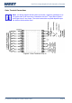
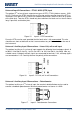
Outer Terminal Connections
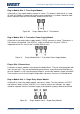
Note: The wiring diagram below shows the Central Terminals (numbered 25 to
42) at the sides of the case rear. Connections for the 2
nd
Input, Base Option 2
and Digital Input C are shown. The actual connections required depends upon
the features and modules fitted.
Figure 8. Outer Terminals 25 to 42