Pro-EC44 2-Loop Graphical Profile Controller & Recorder Pro-EC44 User Guide 59540-1
Pro-EC44 2-Loop Graphical Profile Controller & Recorder This manual supplements the Concise Product manual supplied with each instrument at the time of shipment. Information in this installation, wiring and operation manual is subject to change without notice. Copyright © October 2013, Danaher Corporation, all rights reserved.
Pro-EC44 2-Loop Graphical Profile Controller & Recorder Warranty and Returns Statement These products are sold by West Control Solutions under the warranties set forth in the following paragraphs.
Pro-EC44 2-Loop Graphical Profile Controller & Recorder How to use this manual This manual is structured to give easy access to the information required for all aspects of the installation and use and of the controller. The main sections are shown here, with a full table of contents at the end. Warranty and Returns Statement .....................................................................................................ii 1 Introduction.................................................................
Pro-EC44 2-Loop Graphical Profile Controller & Recorder 1 Introduction This product is a 1/4 DIN size (96 x 96mm front) microprocessor based graphical process controller, featuring a 160 x 80 pixel, monochrome LCD with dual colour (red/green) backlight. It operates from 100-240V at 50/60 Hz or 24V-48V AC/DC, depending on the model purchased. It can measure and control up to two process variables from a variety of sources such as temperature, pressure, flow and level.
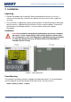
Pro-EC44 2-Loop Graphical Profile Controller & Recorder 2 Installation Unpacking 1. Remove the product from its packing. Retain the packing for future use, in case it is necessary to transport the instrument to a different site or to return it to the supplier for servicing. 2. The instrument is supplied with a panel gasket and push-fit mounting clamp. A multi-page concise manual is supplied with the instrument, in one or more languages. Examine the delivered items for damage or defects.
Pro-EC44 2-Loop Graphical Profile Controller & Recorder Instruments may be mounted side-by-side in a multiple installation, but instrument to panel moisture and dust sealing will be compromised. Allow a 20mm gap above, below and behind the instrument for ventilation. The cut-out width (for n instruments) is: (96n - 4) mm or (3.78n - 0.16) inches If panel sealing must be maintained, mount each instrument into an individual cut-out with 10mm or more clearance between the edges of the holes.
Pro-EC44 2-Loop Graphical Profile Controller & Recorder 3 Field Upgrade Options Plug-Modules and Upgradeable Functions Plug-Modules can be either pre-installed at the time of manufacture, or retrofitted in the field to expand the capabilities of the controller. Contact your supplier to purchase these items.
Pro-EC44 2-Loop Graphical Profile Controller & Recorder Board Mounting Struts (x4) Front Panel Removal Latch (x1) Plug-in Module A Plug-in Module 3 Power Supply Board 2nd Universal Input & Base Option 2 Board 1st Universal Input & Base Option 1 Board Plug-in Module 1 Plug-in Module 2 USB/Digital Input C Option Board Figure 3.
Pro-EC44 2-Loop Graphical Profile Controller & Recorder Main Board Connectors POWER SUPPLY BOARD Transformer Colour Code Module Slot 3 Connector PL4B Module Slot A Connectors PL5, & PL6 100-240V (Yellow) 24-48V(Blue) Module Slot 1 Connectors PL7 & PL8 Display Board Connections PC Configurator Socket SK1 Module Slot 2 Connector PL4A 1st UNIVERSAL INPUT / BASE OPTION 1 BOARD Figure 4.
Pro-EC44 2-Loop Graphical Profile Controller & Recorder Removing/Replacing Option Modules 1. To remove or replace Plug-in Modules 1, 2, 3 or A it is necessary to detach the power supply and input boards from the front panel by lifting first the upper and then lower mounting struts. 2. Remove or fit the modules to the connectors on the power supply and input boards. The location of the connectors is shown below.
Pro-EC44 2-Loop Graphical Profile Controller & Recorder Data Recorder Board If installed, the Data Recorder memory and Real Time Clock (RTC) components are located on a plug-in daughter board attached to the front Display/CPU board. CAUTION: Servicing of the Data Recorder/RTC circuit and replacement of the lithium battery should only be carried out by a technically competent technician.
Pro-EC44 2-Loop Graphical Profile Controller & Recorder 4 Electrical Installation CAUTION: Installation should be only performed by technically competent personnel. It is the responsibility of the installing engineer to ensure that the configuration is safe. Local Regulations regarding electrical installation & safety must be observed (e.g. US National Electrical Code (NEC) or Canadian Electrical Code). Avoiding EMC Problems This controller has passed EMC compliance tests to EN61326.
Pro-EC44 2-Loop Graphical Profile Controller & Recorder Noise Suppression at Source If possible, eliminate mechanical contact relays and replace with solid-state relays. Noise-generating devices such as Ignition transformers, arc welders, motor drives, relays and solenoids should be mounted in a separate enclosure. If this is not possible, separate them from the instrumentation, by the largest distance possible.
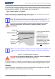
Pro-EC44 2-Loop Graphical Profile Controller & Recorder Sensor Placement (Thermocouple or RTD) If a temperature probe is to be subjected to corrosive or abrasive conditions, it must be protected by an appropriate thermowell. Probes must be positioned to reflect the true process temperature: 1. In a liquid media - the most agitated area 2.
Pro-EC44 2-Loop Graphical Profile Controller & Recorder Pre-wiring – Cautions, Warnings & Information CAUTION: Installation should be only performed by technically competent personnel. It is the responsibility of the installing engineer to ensure that the configuration is safe. Local Regulations regarding electrical installation & safety must be observed (e.g. US National Electrical Code (NEC) or Canadian Electrical Code).
Pro-EC44 2-Loop Graphical Profile Controller & Recorder Connections and Wiring Central Terminal Connections Note: The wiring diagram below shows all possible combinations to the main connections (numbered 1 to 24) in the centre of the case rear. The actual connections required depends upon the features and modules fitted. . Figure 7. Central Terminals 1 to 24 WARNING: CHECK THE INFORMATION LABEL ON THE CASE TO DETERMINE THE CORRECT VOLTAGE BEFORE CONNECTING TO A LIVE SUPPLY.
Pro-EC44 2-Loop Graphical Profile Controller & Recorder Outer Terminal Connections Note: The wiring diagram below shows the Central Terminals (numbered 25 to 42) at the sides of the case rear. Connections for the 2nd Input, Base Option 2 and Digital Input C are shown. The actual connections required depends upon the features and modules fitted. Figure 8.
Pro-EC44 2-Loop Graphical Profile Controller & Recorder Power Connections WARNING: CHECK THE INFORMATION LABEL ON THE CASE TO DETERMINE THE CORRECT VOLTAGE BEFORE CONNECTING TO A LIVE SUPPLY. CAUTION: This equipment is designed for installation in an enclosure that provides adequate protection against electric shock. An isolation switch should be located in close proximity to the unit, in easy reach of the operator and appropriately marked.
Pro-EC44 2-Loop Graphical Profile Controller & Recorder Universal Input 1 Connections Universal Input 1 is present on all models. This input is normally used for the measured variable signal from a process to be controlled. It can be connected to thermocouples; resistance temperature detectors; analogue mA; mV or V DC signals. The input settings are in the Input 1 Configuration sub-menu. Connections for the various types are shown below.
Pro-EC44 2-Loop Graphical Profile Controller & Recorder Universal Input 1 Connections - Linear Volt, mV or mA input The input supports the following linear/analogue signals: 0 to 50mV; 10 to 50mV; 0 to 5V; 1 to 5V; 0 to 10V; 2 to 10V; 0 to 20mV; 4 to 20mA from any suitable source. Voltage & millivolt signals are connected to terminals 2 & 3, milliamp signals are connected to 1 & 3. Carefully observe the position & polarity of the connections. Figure 13.
Pro-EC44 2-Loop Graphical Profile Controller & Recorder Universal Input 2 Connections – PT100 / NI120 (RTD) input The optional 2nd universal input, supports two types of RTD. PT100 (platinum sensor, 100Ω at 0°C). For three wire RTDs, connect the resistive leg and the common legs of the RTD as illustrated. For a two wire RTD a wire link should be fitted across terminals 35 & 36 (in place of the third wire). Two wire RTDs should only be used when the leads are less than 3 metres long.
Pro-EC44 2-Loop Graphical Profile Controller & Recorder Base Option 1 Base Option 1 provides one or two factory fitted outputs. A relay designated as Output 4 is fitted on all models, and an optional linear mA/V DC designated as Output 6. Base options cannot be added after manufacture. The functions of outputs 4 & 6 are set in the Output Configuration sub-menu. Connect as illustrated below.
Pro-EC44 2-Loop Graphical Profile Controller & Recorder Base Option 2 Linear Output 7 Part of base option 2, Output 7 is an optional linear mV/V DC analogue output. The type & range are selectable from 0 to 5, 0 to 10, 2 to 10V & 0 to 20 or 4 to 20mA. . Figure 21. Linear Output 7 Connections Plug-in Module Slot 1 Connections A selection of plug-in modules are available for Module Slot 1. They can be fitted during manufacture, or purchased and fitted later by the user.
Pro-EC44 2-Loop Graphical Profile Controller & Recorder Plug-in Module Slot 1 - Triac Output Module If fitted with a triac output module, connect as shown. This output is rated at 0.01 to 1 amp @ 280V AC 50/60Hz. Isolated from all other inputs and outputs. A snubber should be fitted across inductive loads to ensure reliable switch off of the Triac. Figure 24.
Pro-EC44 2-Loop Graphical Profile Controller & Recorder Plug-in Module Slot 2 - Dual Relay Output Module If fitted with a dual relay output module, connect as shown. This module has two independent SPST relays for outputs 2A and 2B, with a shared common terminal. The contacts are rated at 2 amp resistive 240 VAC. If used to switch mains voltages, the supply should be separate from the instruments mains supply and the contacts should be correctly switched and fused. Figure 27.
Pro-EC44 2-Loop Graphical Profile Controller & Recorder Plug-in Module Slot 2 - Triac Output Module If fitted with a Triac output module, connect as shown. This output is rated at 0.01 to 1 amp @ 280V AC 50/60Hz. Isolated from all other inputs and outputs. A snubber should be fitted across inductive loads to ensure reliable switch off of the Triac. Figure 30.
Pro-EC44 2-Loop Graphical Profile Controller & Recorder Plug-in Module Slot 3 - Dual Relay Output Module If fitted with a dual relay output module, connect as shown. This module has two independent SPST relays for outputs 3A and 3B, with a shared common terminal. The contacts are rated at 2 amp resistive 240 VAC. If used to switch mains voltages, the supply should be separate from the instruments mains supply and the contacts should be correctly switched and fused. Figure 33.
Pro-EC44 2-Loop Graphical Profile Controller & Recorder Plug-in Module Slot 3 - Triac Output Module If fitted with a Triac output module, connect as shown. This output is rated at 0.01 to 1 amp @ 280V AC 50/60Hz. Isolated from all other inputs and outputs. A snubber should be fitted across inductive loads to ensure reliable switch off of the Triac. Figure 36.
Pro-EC44 2-Loop Graphical Profile Controller & Recorder Plug-in Module Slot A - Ethernet Communications Module If fitted with the Ethernet communication module, the communications protocol available is Modbus TCP. Isolated from all inputs/outputs. If necessary, cut out the removable panel to access the RJ45 connector through the top of the case. No rear connections are required.
Pro-EC44 2-Loop Graphical Profile Controller & Recorder Option C Connections Option C offers a factory fitted multiple digital input option. The board also accommodates the USB port if that is option is fitted. The USB port does not have connections on the rear terminal, it is accessed via the front panel. Option C Connections – Multiple Digital Input Module If the Multiple Digital Input option is fitted, the connections are as illustrated.
Pro-EC44 2-Loop Graphical Profile Controller & Recorder Special Wiring Considerations for Valve Motor Control Valve Motor Drive (VMD) controllers require two identical outputs to be assigned to position the valve. One to open and one to close the valve. These outputs can be two single relays, two triacs, two SSR drivers or one dual relay, but it is recommended to use two single relays (SPDT change-over contacts), and to interlock the relay wiring as shown.
Pro-EC44 2-Loop Graphical Profile Controller & Recorder 5 Powering Up CAUTION: Ensure safe wiring practices have been followed. When powering up for the first time, disconnect the output connections. The instrument must be powered from a supply according to the wiring label on the side of the unit. The supply will be either 100 to 240V AC, or 24/48V AC/DC powered.
Pro-EC44 2-Loop Graphical Profile Controller & Recorder LED Functions There are four red LEDs that by default indicate the status of the primary & secondary outputs, automatic tuning and alarm status. The top line of the graphical display has four labels for LED indicators. The function of these LEDs and their display labels can be changed using the PC configuration software. The information in this manual assumes standard functions for these LEDs.
Pro-EC44 2-Loop Graphical Profile Controller & Recorder 6 Messages & Error Indications Plug-in Module Problems If an invalid or unknown module is detected in one of the plug-in module slots during the power-up self-test, the message “Fault Found, Press R, for details” is shown. This is followed by “Replace faulty module in Module Slot n, Press R,” (where n is the faulty slot location).
Pro-EC44 2-Loop Graphical Profile Controller & Recorder Auxiliary Input Over-range or Under-range Indication If the auxiliary Remote Setpoint input is more than 5% above than the Auxiliary Input Upper Limit, its value is replaced by the word “HIGH” to indicate that it is out of range. If the auxiliary Remote Setpoint input is more than 5% below than the Auxiliary Input Lower Limit, its value is replace by the word “LOW” to indicate that it is out of range.
Pro-EC44 2-Loop Graphical Profile Controller & Recorder 7 Application Setup Before beginning configuration, consider how the controller will be used in your application. For instance, how many control loops are needed, is cascade or ratio control required, will the unit control a valve motor, do you need setpoint profiling etc. Consideration should also be given to the output types, alarms and tuning method.
Pro-EC44 2-Loop Graphical Profile Controller & Recorder Process Type* Loop 1 / Master Control Control (only if 2nd Configuration: Configuration: input fitted) Control Select Control Type Two Loops* Standard PID Primary Only Input 2 Control Select Control Type Configuration | = Control Standard = Single Input 2 Usage Primary / Secondary = Standard Control Type = Dual Valve Motor Drive Control Select = VMD (TPSC) Control +Feedback* Valve Motor Drive Input 2 Control Select Configuration | = VMD (TPSC) Input 2
Pro-EC44 2-Loop Graphical Profile Controller & Recorder What are the sources for the setpoints? Local setpoint(s) only, or a remote setpoint input (see page 216 & 227). Profile Control (see page 87). Is Input re-configuration required? Analogue input calibration & scaling (see page 70). Digital input functions (see page 75). Which other features are to be used? Data Recorder (see page 97). Serial Communications (see page 109). USB Interface (see page 96).
Pro-EC44 2-Loop Graphical Profile Controller & Recorder 8 Operation and Configuration Menus This section contains information on all of the controller’s modes and the configuration menus. Operation Mode This is the mode used during normal operation of the instrument. It can be accessed from the Main Menu, and is the usual mode entered at power-up. The available displays are dependent upon the features/options fitted and the way in which it has been configured.
Pro-EC44 2-Loop Graphical Profile Controller & Recorder OPERATION MODE SCREEN SEQUENCE All possible screens are listed below. The sequence shown depends on the configuration and status. E.g. settings for “Loop 2” only apply if 2nd input is fitted and configured for 2-loop control. ◘ Some screens are only shown if set to do so in Display Configuration. After 2 minutes without key activity, the most screens revert to the Base Operating Screen. Screens marked do not revert automatically.
Pro-EC44 2-Loop Graphical Profile Controller & Recorder Cascade Control: Normal Operation LED Indicators LED Function Labels Master Process Value Cascade Status Master Setpoint (Slave SP if Cascade Open) Slave Process Value Control Deviation (±5% of span) & Power Graphs CASCADE CONTROL Default LED indicator functions are PRI, SEC, TUNE & ALARM - the functions and their labels can be altered only with the PC configuration software.
Pro-EC44 2-Loop Graphical Profile Controller & Recorder Two Control Loops: Profiler Status LED Indicators LED Function Labels Engineering Units* Profile Status Indicators*: Process Variable Values & ► Run, ▌▌ Held, ■ Setpoints* Stopped Loop Descriptions* Profile Name & Progress Segment No. Type & Progress 2-LOOP PROFILE STATUS * = in loop 1 & 2 screen area (or Delayed Start Time) Default LED indicator functions are as shown in the initial base screen.
Pro-EC44 2-Loop Graphical Profile Controller & Recorder Setpoint Ramp Rate The setpoint ramp rate adjustment for loop 1. Adjustable between 0.1 and – Loop 1 9999.0 display units per hour. When set to “OFF”, setpoint changes will step immediately to the new value - ◘ only shown if set to do so in Display. Note: If the setpoint ramp feature is used, it disables pre-tune completely, and if self-tune is used, it will only calculate new terms after the ramp has completed and the setpoint is constant.
Pro-EC44 2-Loop Graphical Profile Controller & Recorder Clear Latched Outputs Recorder Memory Full Warning Manual Recording Trigger Hold down D or U for 3 seconds to clear the selected latched output – An output will only reset if the condition that caused it to latch on is no-longer present. ◘ only shown if set to do so in Display Configuration. Indicates that the Data Recorder memory is full and that recording has either stopped or is overwriting older data if in FIFO recording mode.
Pro-EC44 2-Loop Graphical Profile Controller & Recorder Main Menu This menu is used to access the various features and configuration settings. The available menus are dependent upon the features and options fitted and how it has been configured. Entry into the Main Menu Holding down Rand pressing U from Operation Mode and most other screens will cause the unit to enter the Main Menu. Each time this key press sequence is made, the instrument moves to the next menu level above.
Pro-EC44 2-Loop Graphical Profile Controller & Recorder Setup Wizard An easy Setup Wizard runs automatically at first ever power-up. Follow the Wizard to setup parameters required for basic applications. The parameters covered by the Setup Wizard are marked with a w in the following sections covering the configuration mode sub-menus. Once completed, the Setup Wizard exits to Operation Mode. The Wizard can be run again at any time from the Main Menu.
Pro-EC44 2-Loop Graphical Profile Controller & Recorder Supervisor Mode This mode is only available if it has been configured from the PC software. Its purpose is to allow selected operators access to a lock-code protected sub-set of the configuration parameters, without providing them with the higher level configuration menu unlock code. The PC software can copy up to 50 parameters from configuration menus for inclusion in the supervisor mode screen sequence.
Pro-EC44 2-Loop Graphical Profile Controller & Recorder Configuration Menu This menu can be used as an alternative to the more limited Setup Wizard when the instrument is configured for the first time in more complex applications, or when further changes are required to the instruments settings. The configuration menu contains a number of sub-menus that allow access to all of the available parameters. The correct settings must be made before attempting to use the instrument in an application.
Pro-EC44 2-Loop Graphical Profile Controller & Recorder Configuration Mode Unlocking Configuration Options CONFIGURATION MENU SCREENS: Enter correct code number to access Configuration Mode. Factory Default value is 10. Select the required Configuration Sub-Menu Option from: Inputs; Control; Outputs; Alarm; Communications; Recorder; Clock; Display; Lock Code or Reset To Defaults. INPUT CONFIGURATION SUB-MENU SCREENS Input 1 Setup - Sub-menu to setup Input 1.
Pro-EC44 2-Loop Graphical Profile Controller & Recorder Input 2 Setup - Sub-menu to setup Input 2. Press D + R to return to Input Menu Input 2 Usage w Input 2 can be used as a standard process input for a second control loop (including its use as part of a cascade), a redundant input or a feedback signal input from a valve or flow meter. Redundant or Feedback disables the input as an independent control loop.
Pro-EC44 2-Loop Graphical Profile Controller & Recorder Input 2 Calibration - Sub-menu to calibrate Input 2. Press D + R to return to Input Menu Calibration Type If input 2 is selected as a standard process input, the user can select the calibration type from base; single or 2-point calibration. Select single to apply a calibration offset across the entire measured range.
Pro-EC44 2-Loop Graphical Profile Controller & Recorder Digital Input Setup - Sub-menu to setup the Digital Inputs. Press D + R to return to Input Menu Digital Input Status A diagnostic status ( = OFF, = ON, Ø = not available) for digital inputs A; C1 to C8 and “Soft “digital inputs S1 to S4. If used for profile selection, it also shows bit pattern type (binary or BCD) and selected profile number.
Pro-EC44 2-Loop Graphical Profile Controller & Recorder CONTROL CONFIGURATION SUB-MENU SCREENS Control Loop 1 - Sub-menu to setup Control Loop 1. Press D + R to return to Input Menu These settings apply to the master loop if the controller has been setup for cascade control. Control Mode Select the fundamental application type, from: Standard; Cascade or Ratio. Refer to the Application Setup section on page 33.
Pro-EC44 2-Loop Graphical Profile Controller & Recorder Set n – Integral Set n – Derivative Set n – Overlap Set n – On/Off Diff Set n - Breakpoint Manual Reset (Bias) Anti Wind-Up Limit Ratio SFAC Ratio NO Primary Cycle Time Secondary Cycle Time Primary Power Lower Limit Primary Power Upper Limit The integral time value (Automatic Reset) for PID Set n (n = up to 5). Adjustable from 1s to 99min 59s or OFF – Only the set(s) in use shown. The derivative time value (Rate) for PID Set n (n = up to 5).
Pro-EC44 2-Loop Graphical Profile Controller & Recorder Secondary Power Lower Limit Secondary Power Upper Limit Sensor Break Pre-set Power Output Motor Travel Time Minimum Motor On Time Valve Open Limit Valve Close Limit Valve Sensor Break Action Setpoint Lower Limit Setpoint Upper Limit Setpoint Ramp Rate Main Setpoint Source Alternate Setpoint Source Main Setpoint Value Alternate Setpoint Value The minimum secondary output power limit.
Pro-EC44 2-Loop Graphical Profile Controller & Recorder Select Active Setpoint Main Setpoint Offset Alternate Setpoint Offset Select if the main or alternate setpoint is to be the current “active” setpoint for this loop. An offset that can be added to the main setpoint (+ve values) or subtracted from it (-ve values) when the instrument is a comms slave in a multi-zone application. This changes the effective setpoint used for control. Caution: It should be set to zero if an offset is not required.
Pro-EC44 2-Loop Graphical Profile Controller & Recorder Set n – Integral Set n – Derivative Set n – Overlap Set n – On/Off Diff Set n - Breakpoint Manual Reset (Bias) Anti Wind-Up Limit Primary Cycle Time Secondary Cycle Time Primary Power Lower Limit Primary Power Upper Limit Secondary Power Lower Limit Secondary Power Upper Limit Sensor Break Pre-set The integral time value (Automatic Reset) for PID Set n (n = up to 5). Adjustable from 1s to 99min 59s or OFF – Only the set(s) in use shown.
Pro-EC44 2-Loop Graphical Profile Controller & Recorder Power Output Motor Travel Time Minimum Motor On Time Slave SP Scale Min Slave SP Scale Max Valve Sensor Break Action Setpoint Lower Limit Setpoint Upper Limit Setpoint Ramp Rate Main Setpoint Source Alternate Setpoint Source Main Setpoint Value Alternate Setpoint Value Select Active Setpoint Main Setpoint Offset Alternate Setpoint Offset remote setpoint input is lost.
Pro-EC44 2-Loop Graphical Profile Controller & Recorder OUTPUTS CONFIGURATION SUB-MENU SCREENS Output n Configuration - Up to 9 outputs listed. Any already used show as “Assigned” but can be changed. If “Digital” is shown, the output is driven directly via a digital input (see input configuration). Relevant screen sequences repeat for outputs fitted. Press D + R to return to Configuration Menu Linear Output n Type w Set the desired type for any linear outputs fitted.
Pro-EC44 2-Loop Graphical Profile Controller & Recorder Alarm n Value w Alarm n Hysteresis Alarm n Minimum Duration w Alarm n Inhibit w Control n Loop Alarm Type w Control n Loop Alarm Time w The Alarm n activation point – The value is limited by the scaled input limits for Process High; Process Low; PV-SP Deviation (+ve above, -ve below setpoint), Band (above or below setpoint) type alarms. Rate of Signal Change is a rate of 0.0 to 99999 (rate in units per minute).
Pro-EC44 2-Loop Graphical Profile Controller & Recorder No Recorder Warning Recording In Progress Warning Pause (Override Trigger) Recorder Status Information DATA RECORDER CONFIGURATION SUB-MENU SCREENS: If the Recorder Configuration menu is entered on an instrument without this option fitted. A warning if recording when attempting to enter recorder configuration. Access to the configuration is denied unless the recording is paused. Select No to continue recording or Yes to enter recorder configuration.
Pro-EC44 2-Loop Graphical Profile Controller & Recorder Activities To Record Multiple process events can be recorded from: Alarm n Status (n = 1 to 7) or Unit turned Off/On. Note: If an alarm changes state between samples, this will also be recorded using extra memory. The remaining recording time is reduced accordingly. Profiler Events To Record Date Format Set Date Set Time The Profiler Event n Status can be recorded (n = 1 to 5).
Pro-EC44 2-Loop Graphical Profile Controller & Recorder Lock Code Configuration LOCK CODE CONFIGURATION SUB-MENU SCREEN Set Lock Codes (passwords) for the following configuration and control menus: Setup Wizard; Configuration Mode; Tuning Menu; Supervisor Mode; USB Menu; Recorder Menu, Profiler Setup and Profiler Menu. Independently adjustable from 1-9999 or OFF. Note: The factory default value is 10 for all lock codes. For security, users are recommended to change these codes.
Pro-EC44 2-Loop Graphical Profile Controller & Recorder Note: During Data Transfer, normal operation carries on in the background, but operator access to other screens is not possible. The transfer of a full memory can take up to 20 minutes. Only begin a transfer when you are certain that access (e.g. setpoint changes) will not be required. Scrolling “Help Text” is shown at the bottom of the screens to aid navigation.
Pro-EC44 2-Loop Graphical Profile Controller & Recorder Recorder Control Menu This menu allows the user to manually start a recording or to delete previous recordings. Refer to the Recorder Configuration sub-menu in Configuration Mode for information about how to setup the data to be recorded and the recording interval and the Data Recorder Option section on page 97 for general information about the recorder feature.
Pro-EC44 2-Loop Graphical Profile Controller & Recorder Recorder Status Information Current information about the data recorder feature, including if a recording is in progress (Recording or Stopped); the recording mode (FIFO or Record Until Memory Is Used); a % memory use bar-graph and the estimated available time remaining based on the data selected and memory left.
Pro-EC44 2-Loop Graphical Profile Controller & Recorder General General Profile Configuration Enable Edit While Running Timer Start Function Sub-menu with global settings affecting all profiles. Press D + R to return to Profile Setup Menu Enables or disables the ability to edit profiles whist a profile is running. Caution: Edits made to the current or next segment of the running profile will take effect until after the profile is restarted. Enable or disable automatic starting of profiles.
Pro-EC44 2-Loop Graphical Profile Controller & Recorder Profile Segment Details Profile Segments: Segment Number Segment Type Settings that apply to individual profile segments Shows the number of the profile segment being created. The maximum number of profiles across all profiles is 255.
Pro-EC44 2-Loop Graphical Profile Controller & Recorder Event n Edit A Profile Header Edit A Profile Segment Select the events to be active during this segment. n = 1 to 5. Note: For end segments, the events selected to be active stay on until the instrument exits from profiler mode or a new profile runs. Note: For end segments, the events selected to be active stay on until the instrument exits from profiler mode or a new profile runs.
Pro-EC44 2-Loop Graphical Profile Controller & Recorder Service & Product Information Mode This is read only information about the instrument, its modules and enabled features. It has contact information to tell the user where they can obtain service, sales or technical support for the product. Normally this is the manufacturer or suppliers’ details. Using the PC software, the user can enter their own contact information. There are 7 lines of text - each up to 25 characters in length.
Pro-EC44 2-Loop Graphical Profile Controller & Recorder Automatic Tuning Menu The automatic tune menu is used to engage pre-tune and/or self-tune to assist setting up proportional bands and the integral and derivative time values used by the control loops. Pre-tune can be used to set PID parameters approximately. Self-tune may then be used to optimise the tuning if required. See the Tuning section on page 99 for more information.
Pro-EC44 2-Loop Graphical Profile Controller & Recorder Engage Self-Tune Self-Tune Status Auto Pre-Tune At Power Up Turns self-tune on/off for the active PID Set. If configured, the TUNE LED indicator is continuously on whilst self-tune is operating - *see below. Note: Self-Tune disabled if control is On-Off or disabled. If engaged during setpoint ramping, profile ramps or pre-tuning it is suspended until the ramp or pre-tune is completed. Shows current self-tune status: Running or Stopped.
Pro-EC44 2-Loop Graphical Profile Controller & Recorder 9 Input Calibration & Multi-point Scaling User Calibration The process inputs can be adjusted to remove sensor errors or to match the characteristics of the attached process. For each loop, independent use of base (unadjusted), single point offset or two point calibration strategies are possible, as is the use of multi-point scaling for the displayed values of linear inputs.
Pro-EC44 2-Loop Graphical Profile Controller & Recorder Two Point Calibration This method is used where an error is not constant across the range. Separate offsets are applied at two points in the range to eliminate both “zero” and “span” errors. To use: 1. Measure and record the error at a low point in the process. 2. Measure and record the error at a high point in the process. 3. Go to the first two point input calibration screen. a. Enter the desired low point value as the Calibration Low PV value. b.
Pro-EC44 2-Loop Graphical Profile Controller & Recorder Multi-point Scaling If an input is connected to a linear input signal (mA, mV or VDC), multi-point scaling can be enabled. This allows the linearization of a non-linear signal. – see Input Configuration SubMenu Screens on page 46. The Scale Input Upper & Lower Limits define the values shown when the input is at its minimum and maximum values. Up to 15 breakpoints can scale the input vs. displayed value between these limits.
Pro-EC44 2-Loop Graphical Profile Controller & Recorder Performing a Calibration Check 1. Setup input 1 for the input signal type to be checked. 2. Power up the instrument and correctly connect the signal source. Leave powered up for at least five minutes for RTD and DC linear inputs, and at least 30 minutes for thermocouple inputs. 3. After the appropriate delay for stabilisation, check the calibration at a number of cardinal points by applying the appropriate input signal.
Pro-EC44 2-Loop Graphical Profile Controller & Recorder 6. If the input is misconnected or an incorrect signal is applied, the calibration will be aborted and the values will not be altered. The display will show “Failed: Signal Too Small!” or “Failed: Signal Too Large!”. Correct the problem and repeat that phase before continuing. 7. Press R to select the next calibration phase. 8. Repeat this process for each input type until all the phases are calibrated.
Pro-EC44 2-Loop Graphical Profile Controller & Recorder 10 Digital Inputs Digital inputs are driven to one of two states (active or inactive) by an applied voltage signal or a contact opening/closing. A total of 9 physical digital inputs are possible on this instrument. A multiple digital input can be installed at time of purchase, and a single plug-in module can be fitted in option slot A.
Pro-EC44 2-Loop Graphical Profile Controller & Recorder Soft Digital Inputs In addition to the physical digital inputs, four “soft” digital inputs are available. They are used to select functions in the same way as the physical inputs. The four soft digital inputs can be configured by combining physical inputs, alarms & events using Boolean logic. Input AND selections are then globally OR’d with the input OR selections, the alarms & the events.
Pro-EC44 2-Loop Graphical Profile Controller & Recorder ┌ ┐ / Retained ┌ ┐ / As configured ┌ ┐ / Retained Loop 2 Self-Tune Select Stop Run Profile Run/Hold Hold Run Profile Hold Segment Release No Action Release Profile Abort No Action Abort █ / As Digital Input Data Recorder Trigger Not Active Active █ / As Digital Input Output n Forcing Off/Open On/Closed █ / As Digital Input Clear All Latched Outputs No Action Reset █ / As Digital Input Output n Clear Latch No Action Rese
Pro-EC44 2-Loop Graphical Profile Controller & Recorder 11 Cascade Control Applications with long time lags (e.g. with two or more capacities such as heated jackets) can be difficult to control with a single control loop. The solution is to split the process into two or more cascaded loops consisting of a Master and Slave(s) acting on a common actuator. Ideally, the slave loop’s natural response time should be at least 5 times faster than the master.
Pro-EC44 2-Loop Graphical Profile Controller & Recorder the slave setpoint. The oil temperature is reduced towards the new slave setpoint. This continues until the system becomes balanced. The result is quicker, smoother control with the ability to cope with changes in the load. Overshoot is minimised and the jacket temperature is kept within acceptable tolerances. Normal Cascade Operation During operation, the master and slave are coupled together and. "Cascade" is displayed.
Pro-EC44 2-Loop Graphical Profile Controller & Recorder To manually tune a cascade: 1. Select Cascade-Open from the Cascade Control menu, breaking the link between the master and slave loops. 2. Set the slave controller setpoint manually to the appropriate value for your application. 3. Tune the slave for relatively fast control (‘proportional only’ is often sufficient). 4. Select Cascade-Closed from the Cascade Control menu to link the master and slave loops, then tune the master/slave combination.
Pro-EC44 2-Loop Graphical Profile Controller & Recorder 12 Ratio Control A ratio control loop is used where the quantity of one of the material is to be controlled in proportion to the measured quantity of a second material. The controller mixes the materials at the desired ratio by adjusting the flow of input 1. The flow of input 2 may be controlled separately, but is not controlled by the ratio control loop itself.
Pro-EC44 2-Loop Graphical Profile Controller & Recorder attempts to make the physical ratio 10. With a setpoint of 1.03 it would attempt to make the ratio 10.3 for 3% excess air. The instantaneous (controlled) process value is calculated from the physical ratio, divided by SFac. Like the setpoint, this is displayed as relative value. E.g. if SFac is 10, with 59.5m3/h airflow measured at x1, 0.
Pro-EC44 2-Loop Graphical Profile Controller & Recorder 13 Redundant Input If the 2nd universal input is fitted, the second input can be configured as a redundant input for the main process input. This increases process security by protecting against the possible loss of valuable product resulting from sensor failure. A second sensor is connected to input 2 so that if the main sensor fails, the instrument automatically switches to this backup or “redundant” sensor.
Pro-EC44 2-Loop Graphical Profile Controller & Recorder 14 Valve Motor Drive / 3-Point Stepping Control When directly controlling the motor of a modulating valve or damper, set the Control Mode to VMD in configuration mode to enable the 3-point stepping Valve Motor Drive control algorithm. The term “3-point stepping” is used because there are 3 output states, open valve, close valve or stopped (no action).
Pro-EC44 2-Loop Graphical Profile Controller & Recorder Position Feedback In VMD mode this instrument uses a boundless (open-loop) 3-point stepping algorithm. It does not require any kind of position feedback in order to correctly control the process and can therefore avoids problems associated with faulty feedback signals. However, where valve feedback is available it can still be displayed in a bar-graph as a percentage open (0 to 100%).
Pro-EC44 2-Loop Graphical Profile Controller & Recorder 15 Setpoint Sources The setpoint is the target value at which the instrument attempts to maintain the process variable. Each loop can have a Main “local” setpoint set from the keypad and an Alternate setpoint. Loop 1 Setpoint Sources Loop 1 can have a Main “local” setpoint set from the keypad and an Alternate setpoint.
Pro-EC44 2-Loop Graphical Profile Controller & Recorder 16 Profiler This section covers the Profiler (or setpoint programmer) option. To confirm if profiling is enabled on your controller, refer to the Service & Product Info menu (see page 67). Introduction The Profiler feature allows the user to store up to 255 profile segments, shared between a maximum of 64 Profiles. Each profile controls the value of the setpoint over time; increasing, decreasing or holding their values as required.
Pro-EC44 2-Loop Graphical Profile Controller & Recorder If the instrument also has the data recorder option, its real time clock (RTC) expands the profiling capabilities by adding Day & Time profile start options, releasing of hold segments at a specific time of day and changing the power fail recovery option to one based on the length of time the power has been off. These features are explained below and in the Profiler Setup and Profile Control menus (See pages 63 & 66).
Pro-EC44 2-Loop Graphical Profile Controller & Recorder Note: If the join target has been deleted the profile sequence will abort and the last profiles abort action will apply. Two Loop Profiles If the instrument is configured to control two control loops, the setpoint of both loops can be maintained when profiling. Both setpoints are synchronised to a common segment timebase, but have independent target setpoints for each of the segments.
Pro-EC44 2-Loop Graphical Profile Controller & Recorder Loop-back Segments A Loop-back segment goes back to a specified segment in the current profile. This action is repeated for the required number of times (1 to 9999) before the profile continues onwards. More than one Loop Segment can be used in a profile, but they cannot cross.
Pro-EC44 2-Loop Graphical Profile Controller & Recorder The Auto-Hold Feature There are independent auto-hold settings for each segment of each loop controlled by the profile. When utilised, auto-hold ensures that the profile and the actual processes remain synchronised. If the process does not closely match the setpoints (within the defined Hold Bands), the profile will be held until it returns within bounds. When Auto-Hold becomes active, the profile status is shown as “Held”.
Pro-EC44 2-Loop Graphical Profile Controller & Recorder Auto Hold on Ramps Held if Auto-Hold set to Above Setpoint or Band Process Variable Hold Band Ramp Setpoint (without AutoHold) Ramp Setpoint (with Auto-Hold) Held if Auto-Hold set to Below Setpoint or Band Figure 53. Auto-Hold On A Ramp Segment During a Ramp segment, the ramp is held at the current setpoint value while the process is outside of the hold band in the selected direction(s).
Pro-EC44 2-Loop Graphical Profile Controller & Recorder Power/Signal Lost Recovery Actions If the power is cut or the input signal is lost while a profile is running, the instrument will use the defined Profile Recovery Method once the signal / power returns. The profile recovery method is set in the profile header. The possible profile recovery options are explained below.
Pro-EC44 2-Loop Graphical Profile Controller & Recorder Profile End Actions Once a running profile ends, that profiles’ Segment End Type defines the action taken by the instrument. If a sequence of profiles are joined together, the End Segment Type of the last profile in the sequence will be carried out when it completes. The end segment type is set in the final profile segment data. The possible profile end actions are explained below.
Pro-EC44 2-Loop Graphical Profile Controller & Recorder Profile Abort Actions If a running profile is forced to end early, the Profile Abort Action defines action taken by the instrument. The profile abort action is set in the profile header. If a profile sequence is forced to end early, the profile abort action of the current segment will be used. The possible abort options are explained below.
Pro-EC44 2-Loop Graphical Profile Controller & Recorder 17 USB Interface The features in this section are available on models fitted with the optional USB Interface. Using the USB Port The USB Interface can be used to upload or download instrument settings to or from a USB memory stick. Easy configuration of multiple instruments is achieved by copying from one instrument to another, or by transferring data from the PC configuration software.
Pro-EC44 2-Loop Graphical Profile Controller & Recorder 18 Data Recorder The optional Data Recorder allows the recording of process conditions to memory over time. It operates independently from the Trend Views. The recorder includes 1Mb of flash memory to store data when powered down and a real time clock (RTC) with a battery backup. CAUTION: Servicing of the Data Recorder/RTC circuit and replacement of the internal lithium battery should be carried out by only a trained technician.
Pro-EC44 2-Loop Graphical Profile Controller & Recorder Uploading Data Recordings can be transferred to a memory stick using the USB Port (See page 96). They can also be uploaded directly to the PC software via the configuration port or RS485/Ethernet communications if fitted. The data is stored in Comma Separated format (.csv) which can be opened and analysed with the optional PC software or opened directly into a spreadsheet. Many third party software programs can also import data in the .csv format.
Pro-EC44 2-Loop Graphical Profile Controller & Recorder 19 Controller Tuning PID Sets & Gain Scheduling Up to 5 sets of PID tuning terms can be entered for each control loop, allowing the instrument to be pre-set for differing conditions. Each set has individual values for the following parameters: Primary Proportional Band; Secondary Proportional Band; On-Off Differential; Integral Time; Derivative time; Overlap/Deadband.
Pro-EC44 2-Loop Graphical Profile Controller & Recorder Automatic Tuning To automatically optimise the controllers tuning terms for the process, you can use Pre-Tune, Self-Tune or Auto Pre-Tune independently for each control loop. Note: Automatic tuning will not engage if either proportional band is set to On/Off control. Also, pre-tune (including an auto pre-tune attempt) will not engage if the setpoint is ramping, if a profile is running, or if the Process Variable is <5% of span from setpoint.
Pro-EC44 2-Loop Graphical Profile Controller & Recorder Pre-tune is selected from the automatic tuning menu. It will not engage if either primary or secondary outputs on a controller are set for On-Off control, during setpoint/profile ramping or if the process variable is less than 5% of the input span from the setpoint. Note: To pre-tune a cascade, first select “Cascade-Open” to tune the PID set(s) on the slave.
Pro-EC44 2-Loop Graphical Profile Controller & Recorder Manually Tuning Tuning Control Loops - PID with Primary Output only This technique balances the need to reach setpoint quickly, with the desire to limit setpoint overshoot at start-up or during process changes. It determines values for the primary proportional band and the integral and derivative time constants that allow the controller to give acceptable results in most applications that use a single control device.
Pro-EC44 2-Loop Graphical Profile Controller & Recorder Tuning Control Loops - PID with Primary & Secondary Outputs This tuning technique balances the need to reach setpoint quickly, with the desire to limit setpoint overshoot at start-up and during process changes. It determines values for the primary & secondary proportional bands, and the integral and derivative time constants that allow the controller to give acceptable results in most applications using dual control (e.g. Heat & Cool).
Pro-EC44 2-Loop Graphical Profile Controller & Recorder Process Variable V = On-going Peak-to-Peak variation T = Time period of oscillation (minutes) dS = Maximum rate of rise dP = Maximum rate of fall R = Ratio Primary proportional band = Pb.P = Time Integral Time = T minutes Derivative Time = Secondary proportional band = R x Pb.P 5. Calculate and enter the PID control parameters (primary proportional band, integral time and derivative time) using the formulas shown, and observe the process. 6.
Pro-EC44 2-Loop Graphical Profile Controller & Recorder 5. Follow the instructions in the diagram below. At each stage, allow sufficient settling time before moving on to the next stage. P.Pb is the Primary Proportional Band, Int.T is the Integral Time Constant. Process Variable START Apply power to the load Does the Time Tb PV continuously Yes oscillate? No Note the time Are the interval Ta Oscillations Yes decaying to zero? Multiply P.Pb No Note the period setting by 1.
Pro-EC44 2-Loop Graphical Profile Controller & Recorder Fine Tuning Small adjustments can be made to correct minor control problems. These examples assume reverse acting control (e.g. heating). Adjust accordingly for direct action. If they do not help solve the problem, re-tune the controller as detailed on the preceding sections. Note: When fine tuning the settings, only adjust one parameter at a time, and allow enough time for the process to settle into its new state each time you change a value.
Pro-EC44 2-Loop Graphical Profile Controller & Recorder Integral Time Constant To find the optimum integral time, decrease its value until the process becomes unstable, then increase it a little at a time, until stability has is restored. Induce a load disturbance or make a setpoint change to verify that the process stabilises. If not increase the value some more and re-test. If the response is too slow, decrease the integral time, but avoid instability.
Pro-EC44 2-Loop Graphical Profile Controller & Recorder Anti Wind-up If after fully optimising the tuning, there is an overshoot of the setpoint at start-up or in response to large setpoint changes, the reset wind-up inhibit point can be reduced to suspend integral action until the process is closer to setpoint. If set too low control deviation can occur (the process settles, but is offset above or below the setpoint). It this is observed, increase the value until the deviation error is removed.
Pro-EC44 2-Loop Graphical Profile Controller & Recorder 20 Serial Communications Supported Protocols Communication with a Modbus RTU or Modbus TCP master device is possible if the appropriate communications module is fitted in option slot A. An RS485 Module is required for Modbus RTU. An Ethernet Module is required for Modbus TCP. The instrument can also act as “setpoint master” over RS485 for multi-zone applications.
Pro-EC44 2-Loop Graphical Profile Controller & Recorder Link Layer A query (data request or command) is transmitted from the Modbus Master to the Modbus Slave. The slave instrument assembles the reply to the master. This instrument is normally a slave device. It can only act as a master when being use as setpoint master controller to broadcast its setpoint to other controllers in a multi-zone application. MODBUS SLAVE MASTER INSTRUMENT QUERY RESPONSE Figure 62.
Pro-EC44 2-Loop Graphical Profile Controller & Recorder Supported Modbus Functions The following Modbus function types are supported by this instrument: Function Code 03 / 04 Modbus Meaning Description Read Holding/Input registers 06 08 16 (0x10 hex) Write Single Register Diagnostics Write Multiple Registers 23 (0x17 hex) Read/Write Multiple Registers Read current binary value of specified number of parameters at given address. Up to 64 parameters can be accessed with one query.
Pro-EC44 2-Loop Graphical Profile Controller & Recorder Function 08 - Loopback Diagnostic Test QUERY: Function 08 - Loopback Diagnostic Test Value Func Diagnostic Code Code 08 00 00 HI LO RESPONSE: Function 08 - Loopback Diagnostic Test Value Func Sub-function Code 08 00 00 HI LO Note: The Response normally returns the same data as the loopback query. Other diagnostic codes are not supported.
Pro-EC44 2-Loop Graphical Profile Controller & Recorder Function Code The original function code with its most significant bit (MSB) set. This offsets it by 0x80, so for example 0x06 becomes 0x86. Exception Code 00 Modbus Meaning Unused Description 01 Illegal function 02 Illegal Data Address Function number is out of range. Write functions: Parameter number is out of range or not supported. (for write functions only).
Pro-EC44 2-Loop Graphical Profile Controller & Recorder Calibration Reminder Parameters Parameter Name & Register Address Integer Int +1 Float Calibration Reminder Enable Dec 1048 17432 34864 Hex 0418 4418 8830 Access RW Calibration Reminder Date Dec 34866 n/a n/a Hex n/a n/a 8832 RW Values & Descriptions Value 0 1 Calibration Reminder Status Disabled Enabled Value Calibration Status This can be entered only as a floating point number.
Pro-EC44 2-Loop Graphical Profile Controller & Recorder 31 32 33 34 35 36 Input 1 Engineering Units Dec 1025 17409 34818 Hex 0401 4401 8802 RW Input 1 Maximum Display Decimal Places Dec 1026 17410 34820 RW Hex 0402 4402 8804 Input 1 Scaled Input Lower Limit Dec 1027 17411 34822 Hex 0403 4403 8806 Input 1 Scaled Input Upper Limit Dec 1028 17412 34824 Hex 0404 4404 8808 Input 1 Process Variable Offset Dec 1029 17413 34826 Hex 0405 4405 880A Input 1 Filter Time Constant Dec 1030 17414 34828 Hex
Pro-EC44 2-Loop Graphical Profile Controller & Recorder Input 1 Multi-point Scaling Enable Dec 1053 17437 34874 RW Hex 041D 441D 883A Input 1 Scale Point 1 Dec 1054 17438 34876 Hex 883C 041E 441E Input 1 Display Point 1 Dec 1055 17439 34878 Hex 041F 441F 883E Input 1 Scale Point 2 Dec 1056 17440 34880 Hex 8840 0420 4420 Input 1 Display Point 2 Dec 1057 17441 34882 Hex 0421 4421 8842 Input 1 Scale Point 3 Dec 1058 17442 34884 Hex 8844 0422 4422 Input 1 Display Point 3 Dec 1059 17443
Pro-EC44 2-Loop Graphical Profile Controller & Recorder Input 1 Scale Point 8 Dec 1068 17452 34904 Hex 8858 042C 442C Input 1 Display Point 8 Dec 1069 17453 34906 Hex 042D 442D 885A Input 1 Scale Point 9 Dec 1070 17454 34908 Hex 885C 042E 442E Input 1 Display Point 9 Dec 1071 17455 34910 Hex 042F 442F 885E RW Multi-Point Scaling Point 8 Percentage of the scaled input where multi-point scaling value 8 is applied. 0.1 to 100.0% *set to 100% ends scaling sequence at that point.
Pro-EC44 2-Loop Graphical Profile Controller & Recorder Input 1 Scale Point 15 Dec 1082 17466 34932 Hex 043A 443A 8874 Input 1 Display Point 15 Dec 1083 17467 34934 Hex 043B 443B 8876 User Calibration Type Dec 1085 17469 34938 Hex 043D 443D 887A RW Multi-Point Scaling Point 15 Percentage of the scaled input where multi-point scaling value 15 is applied. 0.1 to 100.0% *set to 100% ends scaling sequence at that point.
Pro-EC44 2-Loop Graphical Profile Controller & Recorder 26 28 29 30 31 32 33 34 35 36 Input 2 Engineering Units Dec 1101 17485 34970 Hex 044D 444D 889A RW Input 2 Maximum Display Decimal Places Dec 1102 17486 34972 RW Hex 044E 444E 889C Input 2 Scaled Input Lower Limit Dec 1103 17487 34974 Hex 044F 444F 889E Input 2 Scaled Input Upper Limit Dec 1104 17488 34976 Hex 0450 4450 88A0 Input 2 Process Variable Offset Dec 1105 17489 34978 Hex 0451 4451 88A2 Input 2 Filter Time Constant Dec 1106 1749
Pro-EC44 2-Loop Graphical Profile Controller & Recorder Input 2 Signal Over Range Flag Dec 1110 17494 34988 Hex 0456 4456 88AC Value 0 1 Process Input Over Range Status Inactive Active (over-range detected) Input 2 Cold Junction Compensation Dec 1111 17495 34990 RW Hex 0457 4457 88AE Value 0 1 CJC Status Disabled Enabled (default) Input 2 Multi-point Scaling Enable Dec 1129 17513 35026 RW Hex 0469 4469 88D2 Value 0 1 Multi-point Scaling Status Disabled Enabled (only if the input type is linear) Inp
Pro-EC44 2-Loop Graphical Profile Controller & Recorder Input 2 Scale Point 7 Dec 1142 17526 35052 Hex 88EC 0476 4476 Input 2 Display Point 7 Dec 1143 17527 35054 Hex 0477 4477 88EE Input 2 Scale Point 8 Dec 1144 17528 35056 Hex 88F0 0478 4478 Input 2 Display Point 8 Dec 1145 17529 35058 Hex 0479 4479 88F2 Input 2 Scale Point 9 Dec 1146 17530 35060 Hex 88F4 047A 447A Input 2 Display Point 9 Dec 1147 17531 35062 Hex 047B 447B 88F6 RW Multi-Point Scaling Point 7 Percentage of th
Pro-EC44 2-Loop Graphical Profile Controller & Recorder Input 2 Display Point 14 Dec 1157 17541 35082 Hex 0485 4485 890A Multi-Point Scaling Display Value For Point 14 RW Value to display at multi-point scaling point 14 Valid between the scaled input lower & upper limits RW Multi-Point Scaling Point 15 Percentage of the scaled input where multi-point scaling value 15 is applied. 0.1 to 100.0% *set to 100% ends scaling sequence at that point.
Pro-EC44 2-Loop Graphical Profile Controller & Recorder Digital input Profile Select Dec 10030 26414 52828 Hex 272E 672E CE5C Digital Input A Usage Dec 10020 26404 Hex 2724 6724 52808 CE48 Digital Input C1 Usage Dec 10021 26405 52810 Hex 2725 6725 CE4A RW RW RW Value 0 1 2 3 4 5 6 Inputs Assigned Exclusively to Profile Selection Digital Input C1 Digital Input C1 to C2 Digital Input C1 to C3 Digital Input C1 to C4 Digital Input C1 to C5 Digital Input C1 to C6 Digital Input C1 to C7 Value 0 1 2 3 4 5
Pro-EC44 2-Loop Graphical Profile Controller & Recorder Digital Input C2 Usage Dec 10022 26406 52812 Hex 2726 6726 CE4C RW 5 6 7 8 9 10 11 12 13 14 15 16 17 18 19 20 21 22 23 24 25 26 27 28 29 30 31 32 33 Control 1 Setpoint Selection Control 2 Setpoint Selection Control 1 Pretune Enable/Disable Control 2 Pretune Enable/Disable Control 1 Selftune Enable/Disable Control 2 Selftune Enable/Disable Clear All Latched Outputs Recorder Start/Stop Profile Run/Hold Profile Abort Profile Hold Release Force Output
Pro-EC44 2-Loop Graphical Profile Controller & Recorder 19 20 21 22 23 24 25 26 27 28 29 30 31 32 33 Digital Input C3 Usage Dec 10023 26407 52814 Hex 2727 6727 CE4E RW Value 0 1 2 3 4 5 6 7 8 9 10 11 12 13 14 15 16 17 18 19 20 21 22 23 24 25 26 27 28 29 30 31 32 33 Pro-EC44 Product Manual - 59540-1 October 2013 Force Output 3 on/off Force Output 3B on/off Force Output 4 on/off Force Output 5 on/off Output 1 Clear Latch Output 2 Clear Latch Output 2B Clear Latch Output 3 Clear Latch Output 3B Clear Latch
Pro-EC44 2-Loop Graphical Profile Controller & Recorder Digital Input C4 Usage Dec 10024 26408 52816 Hex 2728 6728 CE50 Digital Input C5 Usage Dec 10025 26409 52818 Hex 2729 6729 CE52 RW RW Value 0 1 2 3 4 5 6 7 8 9 10 11 12 13 14 15 16 17 18 19 20 21 22 23 24 25 26 27 28 29 30 31 32 33 Usage for Digital Input C4 Unused Control 1 Enable Disable Control 2 Enable Disable Control 1 Auto/Manual Control 2 Auto/Manual Control 1 Setpoint Selection Control 2 Setpoint Selection Control 1 Pretune Enable/Disable
Pro-EC44 2-Loop Graphical Profile Controller & Recorder 13 14 15 16 17 18 19 20 21 22 23 24 25 26 27 28 29 30 31 32 33 Digital Input C6 Usage Dec 10026 26410 52820 Hex 272A 672A CE54 RW Value 0 1 2 3 4 5 6 7 8 9 10 11 12 13 14 15 16 17 18 19 20 21 22 23 24 25 26 Pro-EC44 Product Manual - 59540-1 October 2013 Profile Run/Hold Profile Abort Profile Hold Release Force Output 1 on/off Force Output 2 on/off Force Output 2B on/off Force Output 3 on/off Force Output 3B on/off Force Output 4 on/off Force Output
Pro-EC44 2-Loop Graphical Profile Controller & Recorder 27 28 29 30 31 32 33 Digital Input C7 Usage Dec 10027 26411 52822 Hex 272B 672B CE56 Digital Input C8 Usage Dec 10028 26412 52824 Hex 272C 672C CE58 RW RW Output 3B Clear Latch Output 4 Clear Latch Output 5 Clear Latch Up Key Press Mimic Down Key Press Mimic Back Key Press Mimic Right Key Press Mimic Value 0 1 2 3 4 5 6 7 8 9 10 11 12 13 14 15 16 17 18 19 20 21 22 23 24 25 26 27 28 29 30 31 32 33 Usage for Digital Input C7 Unused Control 1 Enable
Pro-EC44 2-Loop Graphical Profile Controller & Recorder Soft Digital 1 Usage Dec 10036 26420 Hex 2734 6734 52840 CE68 RW 6 7 8 9 10 11 12 13 14 15 16 17 18 19 20 21 22 23 24 25 26 27 28 29 30 31 32 33 Control 2 Setpoint Selection Control 1 Pretune Enable/Disable Control 2 Pretune Enable/Disable Control 1 Selftune Enable/Disable Control 2 Selftune Enable/Disable Clear All Latched Outputs Recorder Digital Start/Stop Trigger Profile Run/Hold Profile Abort Profile Hold Release Force Output 1 on/off Force O
Pro-EC44 2-Loop Graphical Profile Controller & Recorder 21 22 23 24 25 26 27 28 29 30 31 32 33 Force Output 4 on/off Force Output 5 on/off Output 1 Clear Latch Output 2 Clear Latch Output 2B Clear Latch Output 3 Clear Latch Output 3B Clear Latch Output 4 Clear Latch Output 5 Clear Latch Up Key Press Mimic Down Key Press Mimic Back Key Press Mimic Right Key Press Mimic Bit 0 1 2 3 4 5 6 7 8 If Bit value = 1 Input n Is Included in OR Selection Digital Input A Digital Input C1 Digital Input C2 Digital Input
Pro-EC44 2-Loop Graphical Profile Controller & Recorder Soft Digital 2 Usage Dec 10037 26421 Hex 2735 6735 52842 CE6A Soft Digital 2 OR Digital Inputs Dec 10042 26426 52852 Hex 273A 673A CE74 RW RW Value 0 1 2 3 4 5 6 7 8 9 10 11 12 13 14 15 16 17 18 19 20 21 22 23 24 25 26 27 28 29 30 31 32 33 Bit 0 1 2 3 4 5 6 7 8 Pro-EC44 Product Manual - 59540-1 October 2013 Usage for "Soft" Digital Input S2 Unused Control 1 Enable Disable Control 2 Enable Disable Control 1 Auto/Manual Control 2 Auto/Manual Contr
Pro-EC44 2-Loop Graphical Profile Controller & Recorder Soft Digital 2 AND Digital Inputs Dec 10043 26427 52854 RW Hex 273B 673B CE76 Bit 0 1 2 3 4 5 6 7 8 If Bit value = 1 Input n Is Included in AND Selection Digital Input A Digital Input C1 Digital Input C2 Digital Input C3 Digital Input C4 Digital Input C5 Digital Input C6 Digital Input C7 Digital Input C8 Soft Digital 2 OR Alarms Dec 10052 26436 52872 Hex 2744 6744 CE88 Bit 0 1 2 3 4 5 6 If Bit value = 1 Alarm n Is Included in OR Selection Alarm 1
Pro-EC44 2-Loop Graphical Profile Controller & Recorder 22 23 24 25 26 27 28 29 30 31 32 33 Force Output 5 on/off Output 1 Clear Latch Output 2 Clear Latch Output 2B Clear Latch Output 3 Clear Latch Output 3B Clear Latch Output 4 Clear Latch Output 5 Clear Latch Up Key Press Mimic Down Key Press Mimic Back Key Press Mimic Right Key Press Mimic Bit 0 1 2 3 4 5 6 7 8 If Bit value = 1 Input n Is Included in OR Selection Digital Input A Digital Input C1 Digital Input C2 Digital Input C3 Digital Input C4 Digi
Pro-EC44 2-Loop Graphical Profile Controller & Recorder Soft Digital 4 Usage Dec 10039 26423 Hex 2737 6737 52846 CE6E Soft Digital 4 OR Digital Inputs Dec 10046 26430 52860 Hex 273E 673E CE7C RW RW Value 0 1 2 3 4 5 6 7 8 9 10 11 12 13 14 15 16 17 18 19 20 21 22 23 24 25 26 27 28 29 30 31 32 33 Bit 0 1 2 3 4 5 6 7 8 Pro-EC44 Product Manual - 59540-1 October 2013 Usage for "Soft" Digital Input S4 Unused Control 1 Enable Disable Control 2 Enable Disable Control 1 Auto/Manual Control 2 Auto/Manual Contr
Pro-EC44 2-Loop Graphical Profile Controller & Recorder Soft Digital 4 AND Digital Inputs Dec 10047 26431 52862 RW Hex 273F 673F CE7E Bit 0 1 2 3 4 5 6 7 8 If Bit value = 1 Input n Is Included in AND Selection Digital Input A Digital Input C1 Digital Input C2 Digital Input C3 Digital Input C4 Digital Input C5 Digital Input C6 Digital Input C7 Digital Input C8 Soft Digital 4 OR Alarms Dec 10056 26440 52880 Hex 2748 6748 CE90 Bit 0 1 2 3 4 5 6 If Bit value = 1 Alarm n Is Included in OR Selection Alarm 1
Pro-EC44 2-Loop Graphical Profile Controller & Recorder RS485 Data Rate Dec 2118 18502 Hex 0846 4846 37004 908C RS485 Parity Dec 2119 Hex 0847 37006 908E 18503 4847 Auxiliary Input A Type Dec 2120 18504 37008 Hex 0848 4848 9090 Target Setpoint Address Dec 2121 18505 37010 Hex 0849 4849 9092 Master Transmit Format Dec 2123 18507 37014 Hex 084B 484B 9096 RW RW RW Value 0 1 2 3 4 5 RS485 Communications Baud Rate 4800 9600 19200 (Default) 38400 57600 115200 Value 0 1 2 Parity Used For RS485 Com
Pro-EC44 2-Loop Graphical Profile Controller & Recorder Plug-in Module Slot 1 Parameters Parameter Name & Register Address Integer Int +1 Float Plug-in Module 1 Type Dec 2130 18514 37028 Hex 0852 4852 90A4 Linear mA/V DC Output 1 Type Dec 2131 18515 37030 Hex 0853 4853 90A6 Digital Output 1 Status Dec 2132 18516 37032 Hex 0854 4854 90A8 Digital Output 1 Latch Enable Dec 2135 18519 37038 Hex 0857 4857 90AE Digital Output 1 Clear Latch Dec 2136 18520 37040 Hex 0858 4858 90B0 Digital Output 1 Latch State
Pro-EC44 2-Loop Graphical Profile Controller & Recorder Output 1 OR Alarm Selection Dec 10107 26491 52982 Hex 277B 677B CEF6 Output 1 OR Event Selection Dec 10108 26492 52984 Hex 277C 677C CEF8 Output 1 AND Alarm Selection Dec 10109 26493 52986 Hex 277D 677D CEFA Output 1 AND Event Selection Dec 10110 26494 52988 Hex 277E 677E CEFC RW RW RW RW Output 1 Retransmit Input 1 Minimum Dec 2152 18536 37072 RW Hex 0868 4868 90D0 Output 1 Retransmit Input 1 Maximum Dec 2153 18537 37074 RW Hex 0869 4869 90D2
Pro-EC44 2-Loop Graphical Profile Controller & Recorder Output 1 Retransmit Input 2 Minimum Dec 2400 18784 37568 RW Hex 0960 4960 92C0 Output 1 Retransmit Input 2 Maximum Dec 2410 18794 37588 RW Hex 096A 496A 92D4 Value For Loop 2 Retransmit Minimum Displayed value at which the retransmission output reaches its minimum level (e.g. 4mA if type is 4-20mA). Adjustable from -9999 to 9999.9 Value For Loop 2 Retransmit Maximum Displayed value at which the retransmission output reaches its maximum level (e.g.
Pro-EC44 2-Loop Graphical Profile Controller & Recorder Output 2 or 2A Function Dec 10101 26485 52970 Hex 2775 6775 CEEA Output 2B Function Dec 10102 26486 Hex 2776 6776 52972 CEEC Output 2 OR Alarm Selection Dec 10111 26495 52990 Hex 277F 677F CEFE Output 2 OR Event Selection Dec 10112 26496 52992 Hex 2780 6780 CF00 RW RW RW RW Value 0 1 2 3 4 5 6 7 8 9 10 11 12 Output 2 or 2A Function Disabled Loop 1 Primary Output Power Loop 1 Secondary Output Power Loop 1 VMD Open Loop 1 VMD Close Loop 2 Prima
Pro-EC44 2-Loop Graphical Profile Controller & Recorder Output 2 AND Alarm Selection Dec 10113 26497 52994 Hex 2781 6781 CF02 Bit 2 3 4 5 6 7 8 If Bit = 1, Alarm n Is Included in AND Selection Alarm 1 Alarm 2 Alarm 3 Alarm 4 Alarm 5 Alarm 6 Alarm 7 Bit 2 3 4 5 6 7 8 If Bit = 1, Event n Is Included in AND Selection Event 1 Event 2 Event 3 Event 4 Event 5 Profile Running Profile End Bit 2 3 4 5 6 7 8 If Bit = 1, Alarm n Is Included in OR Selection Alarm 1 Alarm 2 Alarm 3 Alarm 4 Alarm 5 Alarm 6 Alarm 7
Pro-EC44 2-Loop Graphical Profile Controller & Recorder Plug-in Module Slot 3 Parameters Parameter Name & Register Address Integer Int +1 Float Plug-in Module 3 Type Dec 2192 18576 37152 Hex 0890 4890 9120 Output 3 or 3A Status Dec 2194 18578 37156 Hex 0892 4892 9124 Output 3B Status Dec 2195 18579 Hex 0893 4893 37158 9126 Digital Output 3 Latch Enable Dec 2197 18581 37162 Hex 0895 4895 912A Digital Output 3 Clear Latch Dec 2198 18582 37164 Hex 0896 4896 912C Digital Output 3 Latch State Dec 2199 185
Pro-EC44 2-Loop Graphical Profile Controller & Recorder 10 11 12 Output 3B Function Dec 10104 26488 Hex 2778 6778 52976 CEF0 Output 3 OR Alarm Selection Dec 10119 26503 53006 Hex 2787 6787 CF0E Output 3 OR Event Selection Dec 10120 26504 53008 Hex 2788 6788 CF10 Output 3 AND Alarm Selection Dec 10121 26505 53010 Hex 2789 6789 CF12 Output 3 AND Event Selection Dec 10122 26506 53012 Hex 278A 678A CF14 RW RW RW RW RW Value 0 1 2 3 4 5 6 7 8 9 10 11 12 OR Alarm Event Reverse AND Alarm Event Direct A
Pro-EC44 2-Loop Graphical Profile Controller & Recorder Output 3B OR Alarm Selection Dec 10123 26507 53014 Hex 278B 678B CF16 Bit 2 3 4 5 6 7 8 If Bit = 1, Alarm n Is Included in OR Selection Alarm 1 Alarm 2 Alarm 3 Alarm 4 Alarm 5 Alarm 6 Alarm 7 Bit 2 3 4 5 6 7 8 If Bit = 1, Event n Is Included in OR Selection Event 1 Event 2 Event 3 Event 4 Event 5 Profile Running Profile End Output 3B AND Alarm Selection Dec 10125 26509 53018 RW Hex 278D 678D CF1A Bit 2 3 4 5 6 7 8 If Bit = 1, Alarm n Is Included
Pro-EC44 2-Loop Graphical Profile Controller & Recorder 8 9 10 11 12 Output 4 Status Dec 3001 19385 Hex 0BB9 4BB9 38770 9772 Digital Output 4 Latch Enable Dec 3002 19386 38772 Hex 0BBA 4BBA 9774 Digital Output 4 Clear Latch Dec 3004 19388 38776 Hex 0BBC 4BBC 9778 Digital Output 4 Latch State Dec 3003 19387 38774 Hex 0BBB 4BBB 9776 Output 4 OR Alarm Selection Dec 10127 26511 53022 Hex 278F 678F CF1E Output 4 OR Event Selection Dec 10128 26512 53024 Hex 2790 6790 CF20 Output 4 AND Alarm Selection Dec 1012
Pro-EC44 2-Loop Graphical Profile Controller & Recorder Output 5 Parameters Parameter Name & Register Address Integer Int +1 Float Linear Output 5 Fitted Dec 3005 19389 38778 Hex 0BBD 4BBD 977A Output 5 Usage Dec 10106 26490 Hex 277A 677A Output 5 Status Dec 3006 19390 Hex 0BBE 4BBE 52980 CEF4 38780 977C Digital Output 5 Latch Enable Dec 3007 19391 38782 Hex 0BBF 4BBF 977E Digital Output 5 Clear Latch Dec 3009 19393 38786 Hex 0BC1 4BC1 9782 Digital Output 5 Latch State Dec 3008 19392 38784 Hex 0BC0
Pro-EC44 2-Loop Graphical Profile Controller & Recorder Output 5 AND Alarm Selection Dec 10133 26517 53034 Hex 2795 6795 CF2A Output 5 AND Event Selection Dec 10134 26518 53036 Hex 2796 6796 CF2C RW RW Bit 2 3 4 5 6 7 8 If Bit = 1, Alarm n Is Included in AND Selection Alarm 1 Alarm 2 Alarm 3 Alarm 4 Alarm 5 Alarm 6 Alarm 7 Bit 2 3 4 5 6 7 8 If Bit = 1, Event n Is Included in AND Selection Event 1 Event 2 Event 3 Event 4 Event 5 Profile Running Profile End Linear Output 6 Parameters Parameter Name &
Pro-EC44 2-Loop Graphical Profile Controller & Recorder Output 6 Retransmit Input 1 Maximum Dec 2183 18567 37134 RW Hex 0887 4887 910E Output 6 Retransmit Input 2 Minimum Dec 2430 18814 37628 RW Hex 097E 497E 92FC Output 6 Retransmit Input 2 Maximum Dec 2431 18815 37630 RW Hex 097F 497F 92FE Value For Loop 1 Retransmit Maximum Displayed value at which the retransmission output reaches its maximum level (e.g. 2mA if type is 4-20mA). Adjustable from -9999 to 9999.
Pro-EC44 2-Loop Graphical Profile Controller & Recorder Output 7 Retransmit Input 2 Maximum Dec 2461 18845 37690 RW Hex 099D 499D 933A Value For Loop 2 Retransmit Maximum Displayed value at which the retransmission output reaches its maximum level (e.g. 2mA if type is 4-20mA). Adjustable from -9999 to 9999.
Pro-EC44 2-Loop Graphical Profile Controller & Recorder Operator Access To Setpoint Edit Dec 4128 20512 41024 RW Hex 1020 5020 A040 Value 0 1 Operator Access To Edit Loop 1 Setpoint No Yes Loop 1 Selected Setpoint Dec 4127 20511 41022 Hex 101F 501F A03E Value 0 1 Selected Setpoint For Loop 1 Main Setpoint Alternate setpoint RO Loop 1 Actual Setpoint Dec 8256 24640 49280 Hex 2040 6040 Effective Setpoint Value Of Selected Loop 1 Setpoint RO C080 The effective setpoint for loop 1 (current instantan
Pro-EC44 2-Loop Graphical Profile Controller & Recorder Loop 2 Target Setpoint Dec 4203 20587 41174 Actual Setpoint Value Of Selected Loop 2 Setpoint RO Hex 106B 506B A0D6 Operator Access To Setpoint Ramp Rate Dec 4204 20588 41176 RW Hex 106C 506C A0D8 Value Operator Access To Setpoint Edit Dec 4206 20590 41180 RW Hex 106E 506E A0DC Value 0 1 Operator Access To Edit Loop 2 Setpoint No Yes Loop 2 Selected Setpoint Dec 4205 20589 41178 Hex 106D 506D A0DA Value 0 1 Selected Setpoint For Loop 2 Main Se
Pro-EC44 2-Loop Graphical Profile Controller & Recorder Loop 1 Control Enable Access Dec 4395 20779 41558 Hex 112B 512B A256 Loop 1 Primary Cycle Time Dec 4301 20685 41370 Hex 10CD 50CD A19A Loop 1 Secondary Cycle Time Dec 4302 20686 41372 Hex 10CE 50CE Loop 1 Control Mode Dec 4390 20774 Hex 1126 5126 A19C 41548 A24C RW Value 0 1 Operator Access To Control Enable/Disable Off On Cycle Time For Primary Control Outputs RW 0.5 to 512.
Pro-EC44 2-Loop Graphical Profile Controller & Recorder Loop 1 Primary Power Upper limit Dec 4321 20705 41410 Hex 10E1 50E1 A1C2 Loop 1 Primary Power Upper limit RW 10 to 100% but must be at least 10% above the primary power lower limit.
Pro-EC44 2-Loop Graphical Profile Controller & Recorder Loop 1 Combined Power Dec 4331 20715 41430 Hex 10EB 50EB A1D6 Loop 1 Pre-Tune Status Dec 4332 20716 41432 Hex 10EC 50EC A1D8 Loop 1 Self-Tune Status Dec 4333 20717 41434 Hex 10ED 50ED A1DA Loop 1 Loop Alarm status Dec 4334 20718 41436 Hex 10EE 50EE A1DC Loop 1 Combined Primary & Secondary Power Level RO RO RO RO Loop 1 Input Failure Pre-set Power Dec 4335 20719 41438 RW Hex 10EF 50EF A1DE Loop 1 Auto Pre-tune Dec 4336 20720 Hex 10F0 50F0 4144
Pro-EC44 2-Loop Graphical Profile Controller & Recorder Loop 1 Valve Open Limit Dec 4377 20761 41522 Hex 1119 5119 A232 Loop 1 PID Set Select Dec 4367 20751 41502 Hex 110F 510F A21E Loop 1 Maximum Valve Position RW PID Set 2 - Primary Prop Band Dec 4347 20731 41462 Hex 10FB 50FB A1F6 RW PID Set 2 - Secondary Prop Band Dec 4348 20732 41464 Hex 10FC 50FC A1F8 PID Set 2 - Integral Time Dec 4349 20733 41466 Hex 10FD 50FD A1FA PID Set 2 - Derivative Time Dec 4350 20734 41468 Hex 10FE 50FE
Pro-EC44 2-Loop Graphical Profile Controller & Recorder PID Set 3 - On/Off Differential Dec 4379 20763 41526 Hex 111B 511B A236 PID Set 3 - On/Off Differential For Loop 1 RW PID Set 4 - Primary Prop Band Dec 4357 20741 41482 Hex 1105 5105 A20A RW PID Set 4 - Secondary Prop Band Dec 4358 20742 41484 Hex 1106 5106 A20C PID Set 4 - Integral Time Dec 4359 20743 41486 Hex 1107 5107 A20E PID Set 4 - Derivative Time Dec 4360 20744 41488 Hex 1108 5108 A210 RW 1109 5109 A212 PID Set 4 - On/
Pro-EC44 2-Loop Graphical Profile Controller & Recorder Loop 1 Gain Set 4 Breakpoint Dec 4371 20755 41510 Hex 1113 5113 A226 Loop 1 Gain Set 5 Breakpoint Dec 4372 20756 41512 Hex 1114 5114 A228 Loop 1 Cascade Mode Dec 4393 20777 41554 Hex 1129 5129 A252 Loop 1 Ratio NO Constant Dec 4387 20771 41542 Hex 1123 5123 A246 Loop 1 Ratio Sfac Constant Dec 4388 20772 41544 Hex 1124 5124 A248 Gain Scheduling PID Set 3 To 4 Switch Point RW Value (SP or PV) gain scheduling switches from PID Set 3 To 4.
Pro-EC44 2-Loop Graphical Profile Controller & Recorder Loop 2 Control Action Dec 4411 20795 41590 Hex 113B 513B A276 RW PID Set 1 - Primary Prop Band Dec 4412 20796 41592 Hex 113C 513C A278 RW PID Set 1 - Secondary Prop Band Dec 4413 20797 41594 Hex 113D 513D A27A PID Set 1 - Integral Time Dec 4414 20798 41596 Hex 113E 513E A27C PID Set 1 - Derivative Time Dec 4415 20799 41598 Hex 113F 513F A27E Loop 2 Manual Reset (Bias) Dec 4416 20800 41600 Hex 1140 5140 A280 RW 1141 5141 A282
Pro-EC44 2-Loop Graphical Profile Controller & Recorder Loop 2 Pre-Tune Set Dec 4497 20881 Hex 1191 5191 Value 0 1 2 3 4 PID Set Pre-tune Will Optimize PID Set 1 PID Set 2 PID Set 3 PID Set 4 PID Set 5 Loop 2 Pre-Tune Engage/disengage Dec 4425 20809 41618 RW Hex 1149 5149 A292 Value 0 1 Pre-Tune Engage/disengage For Loop 2 Pre-Tune OFF Run Pre-Tune Loop 2 Self-Tune Engage/disengage Dec 4426 20810 41620 RW Hex 114A 514A A294 Value 0 1 Self-Tune Engage/disengage For Loop 2 Self-Tune OFF Self-Tune ON
Pro-EC44 2-Loop Graphical Profile Controller & Recorder Pre-Tune Secondary Status Dec 4441 20825 41650 Hex 1159 5159 A2B2 Self-Tune Secondary Status Dec 4442 20826 41652 Hex 115A 515A A2B4 Loop 2 Anti Wind-up Limit Dec 4491 20875 41750 Hex 118B 518B A316 Loop 2 Motor Travel Time Dec 4443 20827 41654 Hex 115B 515B A2B6 Loop 2 Minimum Motor On Time Dec 4444 20828 41656 Hex 115C 515C A2B8 Loop 2 Valve Break Action Dec 4501 20885 41770 Hex 1195 5195 A32A Loop 2 Minimum Valve Position Dec 4476 208
Pro-EC44 2-Loop Graphical Profile Controller & Recorder PID Set 2 - Integral Time Dec 4449 20833 41666 Hex 1161 5161 A2C2 PID Set 2 - Derivative Time Dec 4450 20834 41668 Hex 1162 5162 A2C4 PID Set 2 - Integral Time For Loop 2 PID Set 2 - Derivative Time For Loop 2 1163 5163 A2C6 PID Set 2 - On/Off Differential Dec 4478 20862 41724 Hex 117E 517E A2FC RW RW PID Set 3 - Primary Prop Band Dec 4452 20836 41672 Hex 1164 5164 A2C8 RW PID Set 3 - Secondary Prop Band Dec 4453 20837 41674 He
Pro-EC44 2-Loop Graphical Profile Controller & Recorder PID Set 4 - Overlap/Deadband Dec 4461 20845 41690 Hex 116D 516D A2DA PID Set 4 - On/Off Differential Dec 4480 20864 41728 Hex 1180 5180 A300 RW RW PID Set 5 - Primary Prop Band Dec 4462 20846 41692 Hex 116E 516E A2DC RW PID Set 5 - Secondary Prop Band Dec 4463 20847 41694 Hex 116F 516F A2DE PID Set 5 - Integral Time Dec 4464 20848 41696 Hex 1170 5170 A2E0 PID Set 5 - Derivative Time Dec 4465 20849 41698 Hex 1171 5171 A2E2 RW
Pro-EC44 2-Loop Graphical Profile Controller & Recorder Alarm Parameters Parameter Name & Register Address Integer Int +1 Float Alarm 1 Input Source Dec 6143 22527 Hex 17FF 57FF 45054 AFFE Alarm 1 Type Dec 6144 Hex 1800 22528 5800 45056 B000 Alarm 1 Value Dec 6145 22529 Hex 1801 5801 45058 B002 1806 5806 RW RW & Descriptions Value 0 1 2 3 4 5 6 7 8 Alarm 1 Source Input 1 Input 2 Aux A Input Control Loop 1 Primary Power Control Loop 1 Secondary Power Control Loop 2 Primary Power Control Loop
Pro-EC44 2-Loop Graphical Profile Controller & Recorder Alarm 1 Main Label Dec 6151 22535 45070 Hex 1807 5807 B00E RW Alarm 1 Alternate Label Dec 6152 22536 45072 Hex 1808 5808 B010 RW Alarm 1 Minimum Duration Dec 6153 22537 45074 Hex 1809 5809 B012 Alarm 2 Input Source Dec 6159 22543 Hex 180F 580F 45086 B01E Alarm 2 Type Dec 6160 Hex 1810 22544 5810 45088 B020 RW RW RW Alarm 2 Value Dec Hex 6161 1811 Main Language Name For Alarm 1 In Status Screen 8 ASCII characters replaci
Pro-EC44 2-Loop Graphical Profile Controller & Recorder Alarm 2 Status Dec 6164 22548 Hex 1814 5814 45096 B028 Alarm 2 Inhibit Status Dec 6165 22549 45098 Hex 1815 5815 B02A RO RO Alarm 2 Label Dec 6167 22551 45102 Hex 1817 5817 B02E RW Alarm 2 Alternate Label Dec 6168 22552 45104 Hex 1818 5818 B030 RW Alarm 2 Minimum Duration Dec 6169 22553 45106 Hex 1819 5819 B032 Alarm 3 Input Source Dec 6175 22559 Hex 181F 581F 45118 B03E Alarm 3 Type Dec 6176 Hex 1820 45120 B040 22560 58
Pro-EC44 2-Loop Graphical Profile Controller & Recorder Alarm 3 Value Dec Hex 6177 1821 Value At Which Alarm 3 Activates 22561 5821 45122 B042 Alarm 3 Rate of Change Value Dec 6182 22566 45132 Hex 1826 5826 B04C Process Variable Rate of Change Alarm Threshold RW Alarm 3 Hysteresis Dec 6178 22562 45124 Hex 1822 5822 B044 Alarm 3 Inhibit Enable/disable Dec 6179 22563 45126 Hex 1823 5823 B046 Alarm 3 Status Dec 6180 22564 Hex 1824 5824 45128 B048 Alarm 3 Inhibit Status Dec 6181 22565 45
Pro-EC44 2-Loop Graphical Profile Controller & Recorder Alarm 4 Type Dec 6192 Hex 1830 22576 5830 45152 B060 RW Alarm 4 Value Dec Hex 6193 1831 22577 5831 45154 B062 Dec 6198 22582 45164 Hex 1836 5836 B06C Dec 6194 22578 45156 Hex 1832 5832 B064 Alarm 4 Inhibit Enable/disable Dec 6195 22579 45158 Hex 1833 5833 B066 Alarm 4 Status Dec 6196 22580 Hex 1834 5834 45160 B068 Alarm 4 Inhibit Status Dec 6197 22581 45162 Hex 1835 5835 B06A Process Variable Rate of Change Alarm Threshold R
Pro-EC44 2-Loop Graphical Profile Controller & Recorder Alarm 5 Input Source Dec 6207 22591 Hex 183F 583F Alarm 5 Type Dec 6208 Hex 1840 22592 5840 45182 B07E 45184 B080 RW RW Alarm 5 Value Dec Hex 6209 1841 Value 0 1 2 3 4 5 6 7 8 Source Input 1 Input 2 Aux A Input Control Loop 1 Primary Power Control Loop 1 Secondary Power Control Loop 2 Primary Power Control Loop 2 Secondary Power Loop 1 Loop 2 Value 0 1 2 3 4 5 6 7 10 11 12 Alarm 5 Type Unused Process High Alarm Process Low Alarm Deviation
Pro-EC44 2-Loop Graphical Profile Controller & Recorder Alarm 5 Alternate Label Dec 6216 22600 45200 Hex 1848 5848 B090 RW Alarm 5 Minimum Duration Dec 6217 22601 45202 Hex 1849 5849 B092 Alarm 6 Input Source Dec 6223 22607 Hex 184F 584F 45214 B09E Alarm 5 Type Dec 6224 Hex 1850 22608 5850 45216 B0A0 RW RW RW Alarm 6 Value Dec Hex 6225 1851 Alternate Language Name For Alarm 5 In Status Screen 8 ASCII characters replacing the title "Alarm 5" in alarm status screens when the alternate l
Pro-EC44 2-Loop Graphical Profile Controller & Recorder Alarm 6 Inhibit Status Dec 6229 22613 45226 Hex 1855 5855 B0AA RO Alarm 6 Label Dec 6231 22615 45230 Hex 1857 5857 B0AE RW Alarm 6 Alternate Label Dec 6232 22616 45232 Hex 1858 5858 B0B0 RW Alarm 6 Minimum Duration Dec 6233 22617 45234 Hex 1859 5859 B0B2 Alarm 7 Input Source Dec 6239 22623 Hex 185F 585F 45246 B0BE Alarm 7 Type Dec 6240 Hex 1860 22624 5860 45248 B0C0 RW RW RW Alarm 7 Value Dec Hex 6241 1861 Value 0 1 Al
Pro-EC44 2-Loop Graphical Profile Controller & Recorder Alarm 7 Inhibit Enable/disable Dec 6243 22627 45254 Hex 1863 5863 B0C6 Alarm 7 Status Dec 6244 22628 Hex 1864 5864 45256 B0C8 Alarm 7 Inhibit Status Dec 6245 22629 45258 Hex 1865 5865 B0CA RW RO RO Alarm 7 Label Dec 6247 22631 45262 Hex 1867 5867 B0CE RW Alarm 7 Alternate Label Dec 6248 22632 45264 Hex 1868 5868 B0D0 RW Alarm 7 Minimum Duration Dec 6249 22633 45266 Hex 1869 5869 B0D2 RW Value 0 1 Alarm 7 Power-up/Setpoint
Pro-EC44 2-Loop Graphical Profile Controller & Recorder Memory Remaining Dec 7554 23938 47876 Hex BB04 1D82 5D82 Remaining Data Recorder Capacity Time Remaining Dec 7555 23939 47878 Hex BB06 1D83 5D83 RO Remaining Data Recorder Time Recorder Auto-Alarm Trigger Dec 7563 23947 47894 Hex 1D8B 5D8B BB16 RO RW Operator Access To Record Trigger Dec Hex 7559 1D87 23943 5D87 47886 BB0E RW Recorder Status In Operator Mode Dec Hex 7560 1D88 23944 5D88 47888 BB10 RW Record Input 1 Process
Pro-EC44 2-Loop Graphical Profile Controller & Recorder Record Loop 1 Primary Power Dec 7576 23960 47920 Hex 1D98 5D98 BB30 Value 0 1 Record Primary Power Value For Loop 1 Do Not Record Primary Power Record Primary Power Record Loop 1 Secondary Power Dec 7577 23961 47922 RW Hex 1D99 5D99 BB32 Value 0 1 Record Secondary Power Value For Loop 1 Do Not Record Secondary Power Record Secondary Power Record Loop 2 Primary Power Dec 7611 23995 47990 Hex 1DBB 5DBB BB76 Value 0 1 Record Primary Power Value F
Pro-EC44 2-Loop Graphical Profile Controller & Recorder Record Cascade Slave Primary Power Dec 7533 23917 47834 RW Hex 1D6D 5D6D BADA Value 0 1 Record Primary Power Value of Cascade Slave Do Not Record Primary Power Record Primary Power Of Slave Record Slave Secondary Power Dec 7538 23922 47844 Hex 1D72 5D72 BAE4 Value 0 1 Record Slave Secondary Power in Cascade Mode Do Not Record Secondary Power Record Secondary Power Of Slave Value 0 1 Record Ratio Mode Input 1 Process Value Do Not Record PV Recor
Pro-EC44 2-Loop Graphical Profile Controller & Recorder Record Event 1 Dec 7599 23983 Hex 1DAF 5DAF 47966 BB5E Record Event 2 Dec 7600 23984 Hex 1DB0 5DB0 47968 BB60 Record Event 3 Dec 7601 23985 Hex 1DB1 5DB1 47970 BB62 Record Event 4 Dec 7602 23986 Hex 1DB2 5DB2 47972 BB64 Record Event 5 Dec 7603 23987 Hex 1DB3 5DB3 47974 BB66 Memory Used Dec 7605 23989 47978 Hex BB6A 1DB5 Date format Dec 7868 Hex 1EBC 5DB5 24252 5EBC 48504 BD78 24253 48506 Hex 5EBD BD7A n/a n/a 48508 BD7C Clock
Pro-EC44 2-Loop Graphical Profile Controller & Recorder Real Time Clock Fitted Dec 7871 24255 48510 Hex 1EBF 5EBF BD7E Day Of The Week Dec 7872 24256 Hex 1EC0 5EC0 48512 BD80 RO RO Value 0 1 Real Time Clock Fitted Not Fitted Fitted Value 1 2 3 4 5 6 7 Day Of Week (calculated from clock date setting) Monday Tuesday Wednesday Thursday Friday Saturday Sunday Values & Descriptions Display & Security Parameter Name & Register Address Integer Int +1 Float LED 1 Label Dec 7656 24040 48080 Hex 5DE
Pro-EC44 2-Loop Graphical Profile Controller & Recorder LED 1 Usage Value Dec 7664 24048 48096 Hex 1DF0 5DF0 BBE0 RW LED 1 Usage. For 8 & 9 see also LED 1 Selections.
Pro-EC44 2-Loop Graphical Profile Controller & Recorder LED 1 Option C Digital Indication Dec 7696 24080 48160 Hex 1E10 5E10 BC20 Bit RW LED 1 Control Indication Dec 7644 24028 48056 Hex 1DDC 5DDC BBB8 0 Digital Input C1 1 Digital Input C2 2 Digital Input C3 3 Digital Input C4 4 Digital Input C5 5 Digital Input C6 6 Digital Input C7 Bit RW LED 2 Usage 7665 24049 48098 Hex 1DF1 5DF1 BBE2 RW If bit =1, the function's status is selected 0 Loop 1 Auto Tune (self-tune=O
Pro-EC44 2-Loop Graphical Profile Controller & Recorder LED 2 Event Indication Bit Dec 7700 24084 48168 Hex 1E14 5E14 BC28 RW LED 2 Slot A & Soft Input Indication Dec 7702 24086 48172 Hex 1E16 5E16 BC2C RW LED 2 Option C Digital Indication Dec 7704 24088 48176 Hex 1E18 5E18 BC30 LED 2 Control Indication Dec 7646 24030 48060 Hex 1DDE 5DDE BBBC 0 Event 1 1 Event 2 2 Event 3 3 Event 4 4 Event 5 5 Profile Running 6 Profile End Bit Digital Input A 1 Soft Digi
Pro-EC44 2-Loop Graphical Profile Controller & Recorder LED 3 Alarm Indication Bit Dec 7706 24090 48180 Hex 1E1A 5E1A BC34 RW LED 3 Event Indication 0 Alarm 1 1 Alarm 2 2 Alarm 3 3 Alarm 4 4 Alarm 5 5 Alarm 6 6 Alarm 7 Bit Dec 7708 24092 48184 Hex 1E1C 5E1C BC38 RW LED 3 Slot A & Soft Input Indication Dec 7710 24094 48188 Hex 1E1E 5E1E BC3C RW LED 3 Option C Digital Indication Dec 7712 24096 48192 Hex 1E20 5E20 BC40 LED 3 Control Indication Dec 7648 24
Pro-EC44 2-Loop Graphical Profile Controller & Recorder 9 Alarm/Events/Digital/Control inverted (Logical NOR of selection) Value 8 (Logical OR selection of Alarm/Events/Digital/Control) turns ON the LED if any of the selected alarms, events, inputs or functions are active. Value 9 (Logical NOR selection of Alarm/Events/Digital/Control) turns OFF the LED if any of the selected alarms, events, inputs or functions are active.
Pro-EC44 2-Loop Graphical Profile Controller & Recorder Backlight Colour Dec 7668 24052 Hex 1DF4 5DF4 48104 BBE8 Display Language Dec 7675 24059 Hex 1DFB 5DFB 48118 BBF6 Display Contrast Dec 7676 24060 48120 Hex BBF8 1DFC 5DFC Invert Display Dec 7677 24061 Hex 1DFD 5DFD 48122 BBFA 48124 Hex BBFC 5DFE 1DFF 5DFF BBFE Tuning Lock Code Dec 7680 24064 48128 Hex BC00 1E00 5E00 1E01 5E01 BC02 Profiler Setup Lock Code Dec 7682 24066 48132 Hex 1E02 5E02 BC04 USB Lock Code Dec 7683 240
Pro-EC44 2-Loop Graphical Profile Controller & Recorder Loop 1 Trend View Sample Rate Dec 9000 25384 50768 Hex 2328 6328 C650 RW Value 0 1 2 3 4 5 6 7 8 9 10 11 Loop 1 Trend View Data Dec 9001 25385 50770 Hex 2329 6329 C652 Trend Sample Interval For Loop 1 Every Second Every 2 Seconds Every 5 Seconds Every 10 Seconds Every 15 Seconds Every 30 Seconds Every Minute Every 2 Minutes Every 5 Minutes Every 10 Minutes Every 15 Minutes Every 30 Minutes RW Value 1 2 3 Values To Display In Loop 1 Trend View
Pro-EC44 2-Loop Graphical Profile Controller & Recorder Instrument Data Parameters Parameter Name & Register Address Integer Int +1 Float Serial Number 1 Dec 210 16594 33188 Hex 81A4 00D2 40D2 Access 211 16595 33190 Hex 00D3 40D3 81A6 Serial Number (part 3) Dec 212 16596 33192 Hex 00D4 40D4 81A8 The digits 9 to 11 of the instrument’s Serial number.
Pro-EC44 2-Loop Graphical Profile Controller & Recorder “For Service” Contact Details - Lines 1 to 7 Contact Details 1 Dec 400 16784 33568 Hex 8320 0190 4190 RW Contact Details 2 Dec Hex 401 0191 16785 4191 33570 8322 RW 7 lines of user definable text - 25 ASCII characters per line which can be read or written using Modbus functions 16 or 23.
Pro-EC44 2-Loop Graphical Profile Controller & Recorder Operator Access To Profile Control Dec 8260 24644 49288 RW Hex 2044 6044 C088 Profile Cycles Run Dec 8247 24631 49262 Hex 6037 C06E Event 1 Status Dec 8249 24633 Hex 2039 6039 49266 C072 2037 Event 2 Status Dec 8250 24634 Hex 203A 603A Event 3 Status Dec 8251 24635 Hex 203B 603B Event 4 Status Dec 8252 24636 Hex 203C 603C Event 5 Status Dec 8253 24637 Hex 203D 603D 49268 C074 49270 C076 49272 C078 49274 C07A 49284 C084 Active Profile Name De
Pro-EC44 2-Loop Graphical Profile Controller & Recorder Current Profile Running Time Dec 8235 24619 49238 Hex 202B 602B Current Profile Running Time RO C056 Current Profile Remaining Time Dec 8236 24620 49240 Hex 202C 602C Current Profile Remaining Time RO C058 Current Segment Running Time Dec 8237 24621 49242 Hex 202D 602D 202E RO C05A 602E C05C Total Hold Time Dec 8239 24623 49246 Hex C05E 202F 602F 2030 6030 C060 Profile Setup Dec 8198 24582 49164 Hex 6006 C00C 2006 The
Pro-EC44 2-Loop Graphical Profile Controller & Recorder 2. Write the first segment using the Command Code value Code WS (0x57, 0x53). This command will fill the next available segment position and link it to the profile created in step 1. 3. Write the second segment, again using Command Code WS. This fills the next available segment position and links it to the segment created in step 2. 4.
Pro-EC44 2-Loop Graphical Profile Controller & Recorder Instruction Sequence to read a profile 1. Use the command RP to read the profile header data 2. Use the command RS to read the 1st segment’s data 3. Use the command RS to read the 2nd segment’s data. 4. Repeat steps 2 and 3 until an end segment is reached. The following rules apply when creating a profile over communications: Profiles must always be terminated with an end segment. Segments cannot be added after an end segment has been added.
Pro-EC44 2-Loop Graphical Profile Controller & Recorder Profile Name Character 1 A/R A/R Profile Name Character 2 A/R A/R Profile Name Character 3 A/R A/R Profile Name Character 4 A/R A/R Profile Name Character 5 A/R A/R Profile Name Character 6 A/R A/R Profile Name Character 7 A/R A/R Profile Name Character 8 A/R A/R Profile Name Character 9 A/R A/R Profile Name Character 10 A/R A/R Profile Name Character 11 A/R A/R Profile Name Character 12 A/R A/R Profile Name Characte
Pro-EC44 2-Loop Graphical Profile Controller & Recorder Creating, Editing or Inserting Segments Creating new segments is only possible when a new profile is being created (see above for instruction for creating a profile at the next available position, or at a position that you specify). An error is returned if the correct sequence is not followed. The Insert Segment command is used to add segments to an existing profile (one that already has an end segment).
Pro-EC44 2-Loop Graphical Profile Controller & Recorder Segment Info B (Byte 4 - High) A/R (Floating point number) The meaning of the data contained in Segment Info B depends on the type of segment it relates to. See below.
Pro-EC44 2-Loop Graphical Profile Controller & Recorder 0 = Operator Null (0) Wait for the operator to release the hold 1 = Time of day Start Time Wait until time of the day “B” in seconds since midnight (recorder only). 2 = Digital input Null (0) Wait for digital input signal Loop Number of times to repeat 1 to 9999 Segment number Join Null (0) Profile number Loop to the specified segment number “B” from this point. Repeat this “A” times.
Pro-EC44 2-Loop Graphical Profile Controller & Recorder Byte Count 04 or 02 04 or 02 Command Code High Byte 68 44 Command Code Low Byte 80 or 65 50 or 41 Profile Number High Byte A/R A/R Profile Number Low Byte A/R A/R CRC High Byte A/R A/R CRC Low Byte A/R A/R Delete A Profile (DP) = 04dec / 0x04hex Delete All Profiles (DA) = 02dec / 0x02hex Delete A Profile (DP) = 80dec / 0x50hex Delete All Profiles (DA) = 65dec / 0x41hex Note: The profile number is not included in the message when de
Pro-EC44 2-Loop Graphical Profile Controller & Recorder Get Segments Remaining Returns the number of unused segments remaining in the instrument. The number will be between 0 and 255, depending on how many have been used in the profiles so far created.
Pro-EC44 2-Loop Graphical Profile Controller & Recorder Command Response Name Response Description Profile Number Low Byte A/R High Byte A/R The number of the profile created or edited Segments Remaining A/R A/R The number of unused segments remaining Command Successfully 0x4F 0x4B The command requested was executed without error Command Not Recognized 0xFF 0xFF The command is not recognized Profile Number Invalid 0xF0 0x00 The profile number specified is not available.
Pro-EC44 2-Loop Graphical Profile Controller & Recorder Read Quantity Of Registers High Byte 0 0 Read Quantity Of Registers Low Byte 19 13 Write Start Address High Byte 32 20 Write Start Address Low Byte 6 6 Write Quantity Of Registers High Byte 0 0 Write Quantity Of Registers Low Byte 2 2 Byte Count 4 4 Command Code High Byte 82 52 Command Code Low Byte 80 50 Profile Number High Byte A/R A/R Profile Number Low Byte A/R A/R CRC High Byte A/R A/R CRC Low Byte A/R A/R Pr
Pro-EC44 2-Loop Graphical Profile Controller & Recorder Profile Start Time (Byte 4 - High) Profile Start Time (Byte 3) Profile Start Time (Byte 2) Profile Start Time (Byte 1 - Low) Profile Start Day High Byte A/R (Floating point number) 0 0 A/R A/R Profile Starting Setpoint High 0 0 Profile Starting Setpoint Low A/R A/R 0 0 A/R A/R Profile Start Day Low Byte Profile Recovery High Byte Profile Recovery Low Byte Profile Recovery Time (Byte 4 - high) The time, in elapsed seconds, from the star
Pro-EC44 2-Loop Graphical Profile Controller & Recorder Profile Number High Byte A/R A/R Profile Number Low Byte A/R A/R Segment Number High Byte A/R A/R Segment Number Low Byte A/R A/R CRC High Byte A/R A/R CRC Low Byte A/R A/R The instrument replies to the Read A Segment request as follows: Read A Segment - Response (from instrument) Field Name Comments Data Dec Hex A/R A/R Function Code 23 17 Byte Count 34 22 Command Response High Byte 82 52 Command Response Low Byte 83
Pro-EC44 2-Loop Graphical Profile Controller & Recorder Auto Hold Type Loop 2 High Byte A/R A/R Auto Hold Type Loop 2 Low Byte A/R A/R 0 = Auto-Hold Off, 1 = Hold above SP, 2 = Hold below SP,3 - Hold above and below SP Auto Hold Value Loop 2 (Byte 4 - High) A/R (Floating point number) Auto Hold Value Loop 2 (Byte 3) Auto Hold Value Loop 2 (Byte 2) Auto Hold Value Loop 2 (Byte 1 - Low) CRC High Byte A/R A/R CRC Low Byte A/R A/R The distance loop 2 can be way from setpoint before Auto-Hold activ
Pro-EC44 2-Loop Graphical Profile Controller & Recorder Read a Profile Name This command requests the name of a specific profile. The instrument responds with the name of the profile number requested.
Pro-EC44 2-Loop Graphical Profile Controller & Recorder Profile Name Character 12 A/R A/R Profile Name Character 13 A/R A/R Profile Name Character 14 A/R A/R Profile Name Character 15 A/R A/R Profile Name Character 16 A/R A/R CRC High Byte A/R A/R CRC Low Byte A/R A/R Read Profile Memory Status This command returns the status of the profile memory used. The response to this command is to return a table of all the profile numbers that are in use.
Pro-EC44 2-Loop Graphical Profile Controller & Recorder 0 or 1 Profile 1 Position 0 or 1 etc….. 0 or 1 0 or 1 0 or 1 0 or 1 CRC High Byte A/R A/R CRC Low Byte A/R A/R Profile 62 Position Profile 63 Position Pro-EC44 Product Manual - 59540-1 October 2013 For each of the 64 possible profile positions, a value of 0 is returned if the position is free, or 1 if the position is empty.
Pro-EC44 2-Loop Graphical Profile Controller & Recorder 21 Glossary Active Setpoint The term Active Setpoint is used to describe the currently selected setpoint when the instrument is in controller mode. Controllers can use the Main local setpoint and/or the Alternate Setpoint. Only one of the setpoints can be active at any time. During profiler control, the setpoint value is controlled by the profiler function.
Pro-EC44 2-Loop Graphical Profile Controller & Recorder Inactive Inactive Active Figure 63.
Pro-EC44 2-Loop Graphical Profile Controller & Recorder Alarm Operation The process and control deviation alarm types are illustrated, together with the action of any associated outputs. Also refer to: Alarm Hysteresis; Alarm Inhibit; Alarm Types; Band Alarm Value; Deviation Alarm; Latching Relay; Logical Alarm Combinations; Loop Alarm; Process High Alarm and Process Low Alarm.
Pro-EC44 2-Loop Graphical Profile Controller & Recorder Alarm Types There are three basic alarm types, Process Alarms, Control Deviation Alarms and Event Based Alarms; plus some special condition alarms. Process Alarms are based on the absolute value of the Process Variable. If the PV rises above a high alarm value, or falls below a low alarm value, the alarm will become active. Control Deviation Alarms are based on the value of the Control Deviation error.
Pro-EC44 2-Loop Graphical Profile Controller & Recorder Auxiliary Input Offset Used to adjust the value of auxiliary input A if it provides a Remote Setpoint. Positive values are added to the remote setpoint value, negative values are subtracted, but the setpoint is still constrained by the setpoint limits. Also refer to: Auxiliary Input; Remote Setpoint; Scaled Input Upper Limit; Scaled Input Lower Limit Setpoint Lower Limit and Setpoint Upper Limit.
Pro-EC44 2-Loop Graphical Profile Controller & Recorder Calibration Adjustment or correction of the displayed values relative to the actual measured values. Refer to the User Calibration section of this manual for calibration use and instructions. Also refer to: Multi-point Scaling and Process Variable. Cascade Control Applications with long time lags (e.g. indirect heat via hot water jackets) can be difficult to control with a single control loop.
Pro-EC44 2-Loop Graphical Profile Controller & Recorder Control Configuration A sub-menu of the configuration menu used to adjust the parameters that relate to the control of the process (enabling control, auto/manual mode, control type and action, PID tuning terms, power limits, sensor break action, setpoint values and setpoint selection). Also refer to: Configuration Mode; Control Action; Control Enable; Local Setpoints; Manual Mode; PID; Setpoint Selection and Tuning.
Pro-EC44 2-Loop Graphical Profile Controller & Recorder Controller An instrument that controls one or more process control loops. For each control loop it compares a process variable to a target setpoint, and attempts to make the process maintain the setpoint value by applying a correcting variable (e.g. turning on a heater or dosing with alkali if controlling pH). The controller uses proportional (P, PI, PD o PID) or On-Off control.
Pro-EC44 2-Loop Graphical Profile Controller & Recorder Derivative Action Derivative action biases the proportional control output to compensate for the rate of change in the process variable. In a typical reverse acting application, derivative power is increased if the PV is rising, or decreased if it is falling. The combined proportional and derivative values adjust the correcting variable until the process stabilises, at which point derivative power becomes zero.
Pro-EC44 2-Loop Graphical Profile Controller & Recorder Display Configuration A sub-menu of configuration mode used to adjust the display (colour & contrast) and to enable access to selected parameters from operation mode. These are: Profile Control; Recorder Start/Stop; Recorder Status; Loop 1 & 2 Setpoint Select; Loop 1 & 2 Auto/Manual Select; Loop 1 & 2 Control Enable/Disable; Loop 1 & 2 Trend View; Loop 1 & 2 Setpoint Ramp Rate.
Pro-EC44 2-Loop Graphical Profile Controller & Recorder Indicator An instrument that displays process values, but lacks control features. Typically, alarm outputs are available that will activate at pre-set PV values. Also refer to: Controller; Limit Controller and Process Variable. Input Configuration A sub-menu of configuration mode, used to adjust the parameters that relate to the process and auxiliary inputs (type, engineering units, decimal places, scaling, filtering etc.).
Pro-EC44 2-Loop Graphical Profile Controller & Recorder Invert Digital Input Digital inputs may be “inverted” so that they are active when off and inactive when on. This is useful if the signal applied to the chosen digital input function is reversed in relation the digital input action. Also refer to: Digital Input. Latching Output Alarm outputs can be set to latch on when they become active.
Pro-EC44 2-Loop Graphical Profile Controller & Recorder Local Setpoints Local setpoints are target setpoint values for the control loops that are entered by the user and stored in the controller. The value of local setpoints can be adjusted within the setpoint limits using the front keypad, or via a serial communications link. The instrument can has two setpoints for each control loop. The main local setpoint and an alternate setpoint.
Pro-EC44 2-Loop Graphical Profile Controller & Recorder Loop Alarm A loop alarm detects faults in the control feedback in the selected loop, by continuously monitoring the process variable response to the control outputs. If any alarm is setup as a loop alarm, it repeatedly checks if the control output is at saturation. If saturation is reached (0% or 100% power for single control type, -100% or +100% for dual control type), an internal timer is started.
Pro-EC44 2-Loop Graphical Profile Controller & Recorder Manual Loop Alarm Time The loop alarm time used is manually set whenever a loop alarm is defined to have a manually set time, or if P, PD or On-Off control is selected. This parameter determines the duration of the output saturation condition after which the loop alarm will be activated. Also refer to: Loop Alarm; On-Off Control; PD; PI and PID.
Pro-EC44 2-Loop Graphical Profile Controller & Recorder Cascade Control is another type of Master & Slave application where the slaves setpoint is set using the master controllers PID power output. Also refer to: Cascade Control; Linear Output; Retransmit Output; Remote Setpoint; Auxiliary Input Offset; Serial Communications and Setpoint. Modbus RTU Modbus RTU is the serial communications protocol used on instruments fitted with the RS485 Communications module into option slot A.
Pro-EC44 2-Loop Graphical Profile Controller & Recorder Modulating Valve A valve that can be positioned anywhere between fully closed and fully open by means of an incorporated motor. A typical application would be controlling temperature in a furnace heated by gas burners. The controller moves the valve to the desired position in order to control the gas flow.
Pro-EC44 2-Loop Graphical Profile Controller & Recorder On-Off Differential A switching differential, centred about the setpoint, when using On-off control. Relay ‘chatter’ can be eliminated by proper adjustment of this parameter, but too large a value may increase process variable oscillation to unacceptable levels. On-off differential is also known as hysteresis or deadband.
Pro-EC44 2-Loop Graphical Profile Controller & Recorder OVERLAP Proportional Band 1 Output Power (%) WITH PID Proportional Band 2 Output 1 Output 2 Output 2 Output 1 Process Variable Overlap (positive value) DEADBAND Output Power (%) WITH PID Proportional Proportional Band 1 Band 2 Output 1 Output 2 Output 2 Output 1 Process Variable Deadband (negative value) Proportional OVERLAP & Band 1 Proportional Band 2 = 0 Output 2 Output 2 ON Output 1 Output 2 OFF WITH ON/OFF Output Power (%
Pro-EC44 2-Loop Graphical Profile Controller & Recorder PD Control Proportional and Derivative (PD) control combines proportional control with derivative action. It is similar to PID control, but without Integral action. Also refer to: Derivative; Integral; PID Control; Proportional Control and Tuning. PI Control Proportional and Integral Control (PI) combines proportional control with integral action. It is similar to PID Control, but without derivative action.
Pro-EC44 2-Loop Graphical Profile Controller & Recorder If self-tune is enabled, it will be suspended while pre-tune runs. A pre-tune can be configured to run at every power up using the Auto Pre-Tune function. Refer to the Automatic Tuning section of this manual for full details. Also refer to: Auto Pre-Tune; PID; Process Variable; Self-Tune; and Tuning. Power Output Limits Used to limit the correcting variable. Normally the control algorithm can set these outputs to any value between 0% and 100%.
Pro-EC44 2-Loop Graphical Profile Controller & Recorder Process Variable (PV) Process Variables are the parameter to be controlled. Each control loop monitors its PV via one of the process inputs. PVs can be any type that can be measured by these circuits. Common types are thermocouple or RTD temperature probes, or pressure, level, flow etc from transducers that convert these parameters into DC linear input signals (e.g. 4 to 20mA).
Pro-EC44 2-Loop Graphical Profile Controller & Recorder Profiler A profiler controls the value of the actual setpoint over time; increasing, decreasing or holding its value as required. This is used in applications where the rate of rise or fall of the process variable must be closely controlled, or where a value must be maintained for a period before moving to the next value. If the Profiler is fitted, up to 64 profiles can be created with 255 segments shared amongst them.
Pro-EC44 2-Loop Graphical Profile Controller & Recorder Recorder Configuration If the data recorder is fitted, a recorder configuration sub-menu is added to configuration mode. This is used to adjust the recorder parameters (recording mode, sample interval, recording triggers and values to record). Also refer to: Configuration Mode; and Data Recorder Recorder Option - Refer to Data Recorder. Recorder Menu If the data recorder is fitted, a recorder menu is added to the main menu.
Pro-EC44 2-Loop Graphical Profile Controller & Recorder Retransmit Output Scale Minimum Scales a linear output if it has been selected to retransmit a process or setpoint value. Retransmit scale minimum defines the point at which the output will be at its minimum value. E.g. for a 0 to 5V output, it is the PV or SP value corresponding to 0V.
Pro-EC44 2-Loop Graphical Profile Controller & Recorder Scaled Input Upper Limit For linear inputs, this parameter is used to scale the displayed process variable. It defines the displayed value when the process variable input is at its maximum value (e.g. if 4 to 20mA represents 0 to 14pH, this parameter should be set to 14).
Pro-EC44 2-Loop Graphical Profile Controller & Recorder Sensor Break Pre-Set Power If a thermocouple or RTD is disconnected or breaks, the instrument detects the condition within 2 seconds, and sets the control loops output(s) to a value defined by the sensor break pre-set power parameter in the control configuration sub-menu. Process, band and deviation alarms behave as though the PV has gone high. Non-zero based linear inputs (e.g.
Pro-EC44 2-Loop Graphical Profile Controller & Recorder Setpoint Upper Limit The maximum value allowed for setpoints, adjustable within the scaled input limits. The value should be set below any level that might cause problems in the process. If the value is moved below the current value of a setpoint, that setpoint will automatically adjust to keep it within bounds. Also refer to: Input Span; Scaled Input Upper Limit; Setpoint and Setpoint Lower Limit.
Pro-EC44 2-Loop Graphical Profile Controller & Recorder Solid State Relay (SSR) An external device manufactured using two silicone controlled rectifiers in reverse parallel. SSRs can replace mechanical relays in most AC power applications. Some special SSRs can switch DC, but most cannot. As a solid-state device, an SSR does not suffer from contact degradation when switching electrical current. Much faster switching cycle times are also possible, leading to superior control.
Pro-EC44 2-Loop Graphical Profile Controller & Recorder Time Proportioning Control Time proportioning control is accomplished by cycling the output on and off during the prescribed cycle time, whenever the process variable is within the proportional band(s). The PID control algorithm determines the ratio of time (on vs. off) to achieve the level of the correcting variable required to remove the control deviation error. E.g.
Pro-EC44 2-Loop Graphical Profile Controller & Recorder Triac A small internal solid state relay, which can be used in place of a mechanical relay for low power AC switching (0.1 to 1 amp AC). Like a relay, the output is time proportioned. However, as solid-state devices, triacs do not suffer from contact degradation so much faster switching cycle times are possible, offering improved control and reliability. A snubber should be fitted across inductive loads to ensure reliable switch off the triac.
Pro-EC44 2-Loop Graphical Profile Controller & Recorder 22 PC Software The primary function of the software is to create, download and store instrument configurations and profiles. If the data recorder feature is fitted, its recordings can be downloaded and analysed via the software. There are several extra features that are only possible via the software.
Pro-EC44 2-Loop Graphical Profile Controller & Recorder The Button bar, Device and View menus are used to access the other software functions. View & Device Menus Instrument Simulation Parameter Configuration Figure 67. Profile Editor Trend Button Bar & View Menu Instrument Simulation The software has a fully functional and interactive instrument simulation that includes a configurable simulated process, allowing the instrument settings to be tested before use. Inputs are simulated in the top panel.
Pro-EC44 2-Loop Graphical Profile Controller & Recorder A communications settings screen is shown whenever the user attempts to connect to the instrument from the software. If the settings are not in-line with the information below, the software may not be able to communicate with the instrument. Connection from PC to Bottom Configuration Socket When using the built-in configuration socket, set the communications parameters as shown here and in the following table.
Pro-EC44 2-Loop Graphical Profile Controller & Recorder Connection from PC/Network to Ethernet Port When using the optional Ethernet communications, set the parameters as shown here. Device connector = Bus PC connector = Ethernet (bus coupler) IP Address = Instrument IP address* Port Address = 502. The supported data rates 10/100BASE-T (10 or 100 Mbps) are automatically detected. Note: *An IP address must be set before connecting via Ethernet. Use the default address of 0.0.0.
Pro-EC44 2-Loop Graphical Profile Controller & Recorder USB Memory Stick Folders & Files If a USB flash drive is used to transfer files between instruments and/or the software, the files must be stored in specific DEVICE, CONFIG and PROFILE folders. When saving files from the software to the USB stick, always ensure they are saved to the correct folder. Local file storage on your PC can be in any location. The USB option also limits the file name to 8 characters plus the 3 digit .bct or .pfl extension.
Pro-EC44 2-Loop Graphical Profile Controller & Recorder Extending Functionality via Software LED Functions & Labels The allocated functions and descriptive labels for the 4 LED indicators can be changed with the PC software, replacing the default PRI; SEC; TUNE; ALARM functions. These parameters can be found in the LED settings section of the software’s Display Configuration functional group.
Pro-EC44 2-Loop Graphical Profile Controller & Recorder Note: Any parameters copied into the custom display screens are not password protected. They can be freely viewed and adjusted by anyone with access to the instrument keypad. Functional Groups Mode Drop Down Parameter List Add Entry Remove Entry Figure 69.
Pro-EC44 2-Loop Graphical Profile Controller & Recorder Profile Creation and Editing Select the Profile Editor from the button bar or view menu. An existing profile file can be opened from the file open menu or button, or uploaded from an instrument connected to the PC via the configuration socket or serial communications module. The new profile can be download to the instrument or saved to disk with a .pfl file extension.
Pro-EC44 2-Loop Graphical Profile Controller & Recorder The segments are shown in Segment Data mode. The last segment type is either End, Join or Repeat Sequence, and cannot be deleted. The user can change any segments’ type and values, or insert additional segments before the selected one. A dynamically scaled graphic shows the setpoint(s) for each segment of the profile, with the current selected segment highlighted in red. The five profile events are shown below the graph.
Pro-EC44 2-Loop Graphical Profile Controller & Recorder The settings button allows trend data channels to be made visible/invisible, or change their colour and scaling. Click & drag your mouse over an area of interest to zoom in (use the unzoom button to cancel) or move the cursor line to that area to see the instantaneous analogue values and the alarm & event statuses.
Pro-EC44 2-Loop Graphical Profile Controller & Recorder 23 Specifications Reference Test Conditions Ambient Temperature: Relative Humidity: Supply Voltage: Source Resistance: RTD Lead Resistance: 20C ±2C. 60 to 70%. 100 to 240V AC 50Hz ±1%. <10Ω for thermocouple input. <0.1Ω/lead balanced (Pt100). Universal Process Inputs General Input 1 and 2 Specifications Input Sample Rate: Input Filter Time Input Resolution: Supply Voltage: Humidity Influence: Temp.
Pro-EC44 2-Loop Graphical Profile Controller & Recorder Thermocouple Performance Calibration: Measurement Accuracy: Complies with BS4937, NBS125 and IEC584. 0.1% of full selected input range 1LSD (Least significant display digit). NOTE: Reduced performance for B Thermocouple from +100 to 600°C. NOTE: PtRh 20% vs PtRh 40% Thermocouple accuracy is 0.25% and has reduced performance below 800°C. Linearization better than better 0.2°C (0.05 typical) for J, K, L, N and T thermocouples; than better than 0.
Pro-EC44 2-Loop Graphical Profile Controller & Recorder DC Linear Performance Display Scaling: Minimum Span: Decimal Point Display: DC Input Multi-Point Linearization: Measurement Accuracy: Maximum Overload: Sensor Break Protection: Scalable from -2000 to 100000 for any DC Linear input type. 100 display units. Decimal point selectable from 0 to 3 places. Note: Rounds to 2 places above 99.999; 1 place above 999.99 and no decimal above 9999.9. Up to 15 scaling values can be defined anywhere between 0.
Pro-EC44 2-Loop Graphical Profile Controller & Recorder Isolation: Sensor Break Detection: Reinforced safety isolation from outputs and inputs Applicable for 4 to 20mA, 1 to 5V and 2 to 10V ranges only. Control goes to the pre-set power value if Auxiliary Input is providing the active setpoint source.
Pro-EC44 2-Loop Graphical Profile Controller & Recorder Output Specifications Output Module Types Plug-in Slot 1: Plug-in Slot 2: Plug-in Slot 3: Base Option 4 & 5: Base Option 6 & 7: Single SPDT Relay, Single SSR Driver, Triac or DC linear. Single SPDT Relay, Dual SPST Relay, Single SSR Driver, Dual SSR Driver, Triac or 24VDC Transmitter Power Supply. Single SPDT Relay, Dual SPST Relay, Single SSR Driver, Dual SSR Driver, Triac or 24VDC Transmitter Power Supply. Slot 4 SPDT Relay (std.).
Pro-EC44 2-Loop Graphical Profile Controller & Recorder Single SSR Driver Output 1-3 Output Performance Positions Drive Capability: Isolation: Optional in Plug-in Modules 1, 2 & 3. 1 x Logic / SSR Driver output at >10VDC into 500Ω minimum. Not isolated from the universal input, Ethernet communications or other SSR driver outputs. Dual SSR Driver Output 2-3 Performance Positions Drive Capability: Optional in Plug-in Modules 2 & 3. 2 x Logic / SSR Driver outputs* at >10VDC into 500Ω minimum.
Pro-EC44 2-Loop Graphical Profile Controller & Recorder 24V Transmitter Power Supply 2-3 Performance Positions Power Rating Optional in Plug-in Modules 2 & 3. 1 x 24V nominal (unregulated) excitation for external circuits & transmitters. Rated at 19 to 28VDC at 20mA. Load 910Ω minimum. Isolation: Reinforced safety isolation from inputs and other outputs. *see Linear output (above) for adjustable 0 to 10V Transmitter Power Supply CAUTION: Only one Transmit PSU is supported by the instrument.
Pro-EC44 2-Loop Graphical Profile Controller & Recorder Ethernet Functions Type: Connection Protocol: Supported Speed: IP Address Allocation: Isolation: General communications (inc. extraction of data recordings, transfer of configuration & profile files to or from the PC software). Ethernet communications module. Locates in plug-in Slot A. Connection via RJ45 socket in case top. Modbus TCP Slave only. 10BaseT or 100BaseT (automatically detected) Via DHCP or manual configuration via PC Tool.
Pro-EC44 2-Loop Graphical Profile Controller & Recorder Alarms Number of Alarms: Alarm Types: Duration & Start-up Inhibit Alarm Hysteresis: Combination Alarm & Events Outputs: Seven alarms are configurable for any supported type. Process High; Process Low; PV-SP Deviation; Band; Control Loop; Rate Of Signal Change per minute – all with optional minimum duration and start-up inhibit. Input Signal Break; % Recorder Memory Used, Control Power High, Control Power Low.
Pro-EC44 2-Loop Graphical Profile Controller & Recorder Data Recorder Option Recording Memory: Recording Interval: Recording Capacity: RTC Battery Type: RTC accuracy: 1Mb non-volatile flash memory (data retained when power is off). 1; 2; 5; 10; 15; 30 seconds or 1; 2; 5; 10; 15; 30 minutes. Dependant on sample rate and number of values recorded. Example: 2 values can be recorded for 21 days at 30 second intervals. More values or faster sample rates reduce the duration. VARTA CR 1616 3V Lithium.
Pro-EC44 2-Loop Graphical Profile Controller & Recorder 24 Pro-EC44 Product Coding Model Code EC44 - x Regional Defaults Non-US defaults 0 USA defaults 1 - x - x - x - x - x - x - x - x - x - x - x - x - x - Sxxx Controller/Recorder Controller C Controller with USB Port U Controller/Recorder X Controller/Recorder with USB Port R Profiler Not fitted 0 Profiler Supply Voltage P 100-240VAC 0 24-48V AC/DC Control Loops 2 One Control Loop 1 One Loop + Auxiliar
Pro-EC44 2-Loop Graphical Profile Controller & Recorder Model Code EC44 - x - x - x - x - x - x - x - x - x - x - x - x - x - x - Sxxx Option C Not fitted 0 Multiple Digital Input HMI & Manual Language 1 English 1 French 2 German 3 Italian 4 Spanish Packing And Manual Options 5 Single Pack with Concise Manual 0 Bulk Pack with 1 Concise Manual per unit – (Minimum 20 pcs) Special Variants 1 Standard Model (Special features not fitted) Blank
Pro-EC44 2-Loop Graphical Profile Controller & Recorder 25 Table of Contents Warranty and Returns Statement .....................................................................................................ii 1 Introduction.............................................................................................................................1 2 Installation ..............................................................................................................................2 Unpacking ..
Pro-EC44 2-Loop Graphical Profile Controller & Recorder LED Functions ........................................................................................................................................... 30 Keypad Functions & Navigation ................................................................................................................ 30 6 Messages & Error Indications .............................................................................................
Pro-EC44 2-Loop Graphical Profile Controller & Recorder The USB Menu ......................................................................................................................................... 60 Entry into the USB Menu .....................................................................................................................60 USB Menu Screens ......................................................................................................................
Pro-EC44 2-Loop Graphical Profile Controller & Recorder Special Wiring Considerations for Valve Motor Control ............................................................................ 84 Position Feedback ..................................................................................................................................... 85 Valve Limiting .....................................................................................................................................
Pro-EC44 2-Loop Graphical Profile Controller & Recorder Ethernet Configuration .......................................................................................................................109 Supported Modbus Functions ................................................................................................................. 111 Function Descriptions ........................................................................................................................
Pro-EC44 2-Loop Graphical Profile Controller & Recorder Auxiliary Input Lower Limit ...................................................................................................................... 207 Auxiliary Input Offset ............................................................................................................................... 208 Auxiliary Input Type.................................................................................................................................
Pro-EC44 2-Loop Graphical Profile Controller & Recorder Input Configuration .................................................................................................................................. 214 Input Filter Time Constant....................................................................................................................... 214 Input Range...........................................................................................................................................
Pro-EC44 2-Loop Graphical Profile Controller & Recorder PLC ......................................................................................................................................................... 223 Pre-Tune ................................................................................................................................................. 223 Power Output Limits ..................................................................................................................
Pro-EC44 2-Loop Graphical Profile Controller & Recorder Setpoint ................................................................................................................................................... 230 Setpoint Upper Limit ............................................................................................................................... 231 Setpoint Lower Limit ........................................................................................................................
Pro-EC44 2-Loop Graphical Profile Controller & Recorder Profiler Option ......................................................................................................................................... 253 Data Recorder Option ............................................................................................................................. 254 Display...........................................................................................................................................
Pro-EC44 2-Loop Graphical Profile Controller & Recorder Austria China France PMA Prozeß- und Maschinen-Automation GmbH Danaher Setra-ICG WEST Control Solutions Liebermannstraße F01 Tianjin Co. Ltd. No. 28 Wei 5 Road France 2345 Brunn am Gebirge The Micro-Electronic Industry Park TEDA Tel.: +33 (1) 77 80 90 40 Tel.: +43 (0)2236 691-121 Xiqing District • Tianjin 300385 Fax: +33 (1) 77 80 90 50 Fax: +43 (0)2236 691-102 Tel.: +86 22 8398 8098 • Sales: +86 400 666 1802 Email: info@west-cs.