
Manual


CONTROL INPUTS DI2, DI3 (OPTION)
The functions of control input di2 on the analog
card and of di2 on the options card are logically
ORed.
Configurable as direct or inverse switches or keys.
Optocoupler input for active triggering.
Nominal voltage 24 V DC external
Current sink (IEC 1131 type 1)
Logic “0” -3...5 V
Logic “1” 15...30 V
Current requirement approx.. 5 mA
TRANSMITTER SUPPLY UT (OPTION)
Power: 22 mA /
≥
18 V
As analog outputs OUT3 or OUT4 and trans
-
mitter supply U
T
are connected to different
voltage potentials, an external galvanic connec
-
tion between OUT3/4 and U
T
is not permissible
with analog outputs.
GALVANIC ISOLATION
Safety isolation
Function isolation
OUTPUTS
RELAY OUTPUTS OUT1...OUT4
Contact type: potential-free changeover contact
Max.contact rating: 500 VA, 250 V, 2A at 48...62 Hz,
resistive load
Min. contact rating: 6V, 1mA DC
Number of electical
switching cycles:
for I = 1A/2A: ≥ 800.000 / 500.000
(at ~ 250V (resistive load)
Note:
If the relays operate external contactors, these
must be fitted with RC snubber circuits to man
-
ufacturer specifications to prevent excessive
switch-off voltage peaks.
OUT3, 4 AS UNIVERSAL OUTPUT
Galvanically isolated from the inputs.
Freely scalable resolution: 11 bits
Current output
0/4...20 mA configurable.
Signal range: 0...approx.22mA
Max. load:
≤
500
Ω
Load effect: no effect
Resolution:
≤
22
µ
A (0,1%)
Accuracy
≤
40
µ
A (0,2%)
Voltage output
0/2...10V configurable
Signal range: 0...11 V
Min. load: ≥ 2k
Ω
Load effect: no effect
Resolution:
≤
11 mV (0,1%)
Accuracy
≤
20 mV (0,2%)
OUT3, 4 used as transmitter supply
Output power: 22 mA /
≥
13 V
OUT3, 4 used as logic output
Load
≤
500
Ω
0/
≤
20 mA
Load > 500
Ω
0/> 13 V
OUTPUTS OUT5/6 (OPTION)
Galvanically isolated opto-coupler outputs.
Grounded load: common positive voltage.
Output rating: 18...32 VDC; ≤ 70 mA
Internal voltage drop: ≤ 1 V with I
max
Protective circuit: built-in against short circuit,
overload, reversed polarity (free-wheel diode
for relay loads).
Technical data
KS 90-1 / KS 92-1 73
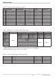
Process value input INP1
Mains supply Supplementary input INP2
Optional input INP3
Digital input di1, di2
Relay OUT1 RS422/485 interface
Relay OUT2 Digital inputs di2, 3
Relay OUT3 Universal output OUT3
Relay OUT4 Universal output OUT4
Transmitter supply U
T
OUT5, OUT6