West Pro-4 user manual – 59559
û BlueControl More efficiency in engineering, more overview in operating: The projecting environment for the BluePort controllers Description of symbols: g General information a General warning l Attention: ESD sensitive devices © PMA Prozeß- und Maschinen-Automation GmbH • Printed in Germany All rights reserved. No part of this document may bereproduced or published in any form or by any means without prior written permission from the copyright owner.
Contents 1 2 2.1 2.2 3 3.1 3.2 3.3 3.4 3.5 3.5.1 3.5.2 3.5.3 3.5.4 3.5.5 3.5.6 3.5.7 3.5.8 3.5.9 3.5.10 3.5.11 3.6 3.7 3.8 3.9 4 4.1 4.2 4.3 Mounting . . . . . . . . . . . . . . . . . . . . . . . . . . . . . . 5 Electrical connections . . . . . . . . . . . . . . . . . . . . . . . 6 Connecting diagram . . . . . . . . . . . . . . . . . . . . . . . 6 Terminal connection. . . . . . . . . . . . . . . . . . . . . . . . . 7 Operation . . . . . . . . . . . . . . . . . . . . . . . . . . . . . 11 Front view . . .
.4.3 4.4.4 Switching attitude non-linear ( CyCl= 2 ) . . . . . . . . . . . . . . . 45 Heating and cooling with constant period ( CyCl= 3 ) . . . . . . . . 46 4.5 Configuration examples . . . . . . . . . . . . . . . . . . . . . . 47 4.5.1 4.5.2 4.5.3 4.5.4 4.5.5 4.5.6 4.5.7 4.5.8 5 5.1 5.2 5.3 5.3.1 5.3.2 6 7 7.1 7.2 On-Off controller / Signaller (inverse) . . . . . . . . . . . 2-point controller (inverse) . . . . . . . . . . . . . . . . . 3-point controller (relay & relay) . . . . . . . . . . . . .
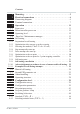
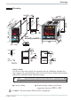
Mounting 1 Mounting min.48 (1.89") (1.77" SP.E SP.2 +0.02 ) 92 +0,8 (3.62" +0.03) Loc security switch F è Ada Err o C SP.E para func Ada Err 45 1200 para func SP.2 96 (3.78") °C °F +0,6 3 4 920.1 44 1199 2 921.2 run 3 SP.E 2 1 SP.2 run 1 96 8 +0,8 ) 5" 6 . (4 92 11 ") (0 1 . .0 .1 4. 0 .0 .4 ") 10 .4 (0 92 +0,8 F KS 92-1 advanced KS 92-1 advanced KS 90-1 advanced 96 8 11 10 48 (1.89") max. 60°C min. 0°C Ü max. 95% rel.
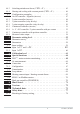
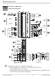
Electrical connections 2 Electrical connections 2.1 Connecting diagram 90...250V 24 V UC 1 2 3 OUT1 4 5 6 2 OUT3 3 10 11 12 V KS90-1.4-... KS90-1.5-... OUT4 13 14 15 V KS90-1.2-... 5 d bc e a 7 di2 4 5 6 7 8 9 10 11 12 13 14 15 (16) 17 7 8 9 OUT2 di1 1 2 3 Option 1 g HC mA f mA 0% 5 INP3 6 KS90-1..-.1...
Electrical connections 2.2 Terminal connection Power supply connection 1 See chapter "Technical data" Connection of outputs OUT1/2 2 2 OUT1/2 heating/cooling Relay outputs (250V/2A), potential-free changeover contact 1 Connection of outputs OUT3/4 3 a relay (250V/2A), potential-free changeover contact universal output b current (0/4...20mA) c voltage (0/2...10V) d transmitter supply e logic (0..20mA / 0..
Electrical connections Connection of inputs di2/3 8 (option) Digital inputs (24VDC external), galvanically isolated, configurable as switch or push-button Connection of output UT 9 (option) Supply voltage connection for external energization Connection of outputs OUT5/6 0 (option) Digital outputs (opto-coupler), galvanic isolated, common positive control voltage, output rating: 18...
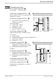
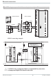
Electrical connections 3 OUT3 transmitter supply 13V 22mA - 10 + 11 11 12 12 13 14 15 13 + 14 - 15 (16) 17 1 3 2 K 1 (2) 10 11 12 RT = 120...
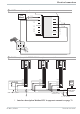
Electrical connections 3 OUT3 as logic output with solid-state relay (series and parallel connection) Series connection Parallel connection SSR _ + SSR _ Imax=22mA + 12 SSR _ 4V SSR _ 10 11 12V + Imax=22mA 4V 12V 12 SSR _ + + Logic 10 11 4V KS90-1 connecting example: L1 L2 Fuse Fuse KS90-1 3 4 5 6 7 8 9 10 11 Logik 12 13 14 15 4 5 6 7 8 9 10 11 12 13 14 Fuse 1 1 2 3 2 Contactor 3 TB 40-1 Temperaturelimiter 1 2 1 TB 40-1 Temperaturelimiter Standard-version (3 Relays): T
Operation 3 Operation 3.1 Front view 1199 °C °F p para ffunc Ada A Err 1200 §" SP.E E SP.2 SP 1 2 2 3 9 0 3 5 6 7 8 ! F $ ( 1 $ % & / ( 2 3 4 920.1 92 o para func 4 Ada Err C 921.2 9 §"! 0 % ( 1 3 5 7 9 ! § 1 SP.E 4 SP.2 / & 3 SP.E 4 5 6 7 8 2 SP.2 1 F / & % $ Statuses of switching outputs OuT.1...
Operation 3.2 Behaviour after power-on After supply voltage switch-on, the unit starts with the operating level. The unit is in the condition which was active before power-off. If the controller was in manual mode at supply voltage switch-off, the controller will re-start with the last output value in manual mode at power-on. 3.3 Operating level The content of the extended operating level is determined by means of BlueControl (engineering tool).
Operation 3.4 Error list / Maintenance manager With one or several errors, the extended operating level always starts with the error list. Signalling an actual entry in the error list (alarm, error) is done by the Err LED in the display. To reach the error list press Ù twice. Err LED status blinks (status 2) lit (status 1) off (status 0) Signification Alarm due to existing error Error removed, alarm not acknowledged No error, all alarm entries deleted - 1199 °C °F para func Ada Err 1200 SP.E SP.
Operation Name HCA Description Heating current alarm (HCA) SSr Heating current short circuit (SSR) LooP Control loop alarm (LOOP) AdA.
Operation g g Saved alarms (Err-LED is lit) can be acknowledged and deleted with the digital input di1/2/3, the è-key or the Ò-key. Configuration, see page 37: ConF / LOGI / Err.r If an alarm is still valid that means the cause of the alarm is not removed so far (Err-LED blinks), then other saved alarms can not be acknowledged and deleted. Self-tuning heating ( ADA.H) and cooling ( ADA.
Operation 3.5 Self-tuning For determination of optimum process parameters, self-tuning is possible. After starting by the operator, the controller makes an adaptation attempt, whereby the process characteristics are used to calculate the parameters for fast line-out to the set-point without overshoot. The following parameters are optimized when self-tuning: Parameter set 1: Pb1 - Proportional band 1 (heating) in engineering units [e.g.
Operation 3.5.2 Optimization after start-up or at the set-point The two methods are optimization after start-up and at the set-point. As control parameters are always optimal only for a limited process range, various methods can be selected dependent of requirements. If the process behaviour is very different after start-up and directly at the set-point, parameter sets 1 and 2 can be optimized using different methods. Switch-over between parameter sets dependent of process status is possible (see page ).
Operation 3.5.4 Step attempt after start-up Condition: - tunE = 0 and sufficient set-point reserve provided or - tunE = 2 The controller outputs 0% correcting variable or Y.Lo and waits, until the process is at rest (see start-conditions on page 8). Subsequently, a correcting variable step change to 100% is output. The controller attempts to calculate the optimum control parameters from the process response.
Operation Optimization-at-the-set-point procedure: The controller uses its instantaneous parameters for control to the set-point. In lined out condition, the controller makes a pulse attempt. This pulse reduces the correcting variable by max. 20% 1, to generate a slight process value undershoot. The changing process is analyzed and the parameters thus calculated are recorded in the controller. The optimized parameters are used for line-out to theset-point.
Operation 3.5.7 Optimization at the set-point for 3-point stepping controller With 3-point stepping controllers, the pulse attempt can be made with or without position feedback. Unless feedback is provided, the controller calculates the motor actuator position internally by varying an integrator with the adjusted actuator travel time. For this reason, precise entry of the actuator travel time (tt), as time between stops is highly important.
Operation 3.5.8 Self-tuning start Start condition: w For process evaluation, a stable condition is required. Therefore, the controller waits until the process has reached a stable condition after self-tuning start. The rest condition is considered being reached, when the process value oscillation is smaller than ± 0,5% of (rnG.H - rnG.L). w For self-tuning start after start-up, a 10% difference from (SP.LO ... SP.Hi) is required. g Self-tuning start can be blocked via BlueControl® (engineering tool) ( P.
Operation 3.5.10 Acknowledgement procedures in case of unsuccessful self-tuning 1. Press keys Ù and È simultaneously: The controller continues controlling using the old parameters in automatic mode. The Err LED continues blinking, until the self-tuning error was acknowledged in the error list. 2. Press key Ò (if configured): The controller goes to manual mode. The Err LED continues blinking, until the self-tuning error was acknowleged in the error list. 3.
Operation 3.5.11 Examples for self-tuning attempts (controller inverse, heating or heating/cooling) Start: heating power switched on Heating power Y is switched off (1). When the change of process value X was constant during one minute (2), the power is switched on (3). At the reversal point, the self-tuning attempt is finished and the new parameter are used for controlling to set-point W. Start: heating power switched off The controller waits 1,5 minutes (1). Heating power Y is switched on (2).
Operation 3.6 Manual self-tuning The optimization aid can be used with units on which the control parameters shall be set without self-tuning. For this, the response of process variable x after a step change of correcting variable y can be used. Frequently, plotting the complete response curve (0 to 100%) is not possible, because the process must be kept within defined limits.
Operation Parameter adjustment effects Parameter Pb1 higher lower td1 higher lower ti1 higher lower Control increased damping reduced damping reduced damping increased damping increased damping reduced damping Formulas K = Vmax * Tu With 2-point and 3-point controllers, the cycle time must be adjusted to t1 / t2 ≤ 0,25 * Tu Line-out of disturbances slower line-out faster line-out faster response to disturbances slower response to disturbances slower line-out faster line-out controller behavior PID PD
Operation 3.8 Alarm handling Max. three alarms can be configured and assigned to the individual outputs. Generally, outputs OuT.1... OuT.6 can be used each for alarm signalling. If more than one signal is linked to one output the signals are OR linked. Each of the 3 limit values Lim.1 … Lim.3 has 2 trigger points H.x (Max) and L.x (Min), which can be switched off individually (parameter = “OFF”). Switching difference HYS.x and delay dEl.x of each limit value is adjustable.
Operation g The variable to be monitored can be selected seperately for each alarm via configuration The following variables can be monitored: w process value w control deviation xw (process value - set-point) w control deviation xw + suppression after start-up or set-point change After switching on or set-point changing, the alarm output is suppressed, until the process value is within the limits for the first time. At the latest after expiration of time 10 ti1, the alarm is activated.
Operation 3.9 Operating structure After supply voltage switch-on, the controller starts with the operating levels. The controller status is as before power off. 1199 1200 Ù 3 sec. 1199 para PArA Ì Ù PASS 1199 para Ù ConF Ì PASS 1199 CAL Ì Ù PASS 1199 End Ù g PArA - level: g ConF - level: At ConF - level, the right decimal point of bottom display line blinks.
Configuration level 4 Configuration level 4.1 Configuration survey LOGI Digital inpu ts Othr Display, operation, interface O.tYP O.Act Y.1 Y.2 Lim.1 Lim.2 Lim.3 dAc.A LP.AL HC.AL HC.SC P.End FAi.1 FAi.2 FAi.3 OuT.0 Out.1 O.Src Out.5/6 Output 5/6 O.tYP O.Act OuT.0 Out.1 O.Src O.FAI Y.1 Y.2 Lim.1 Lim.2 Lim.3 dAc.A LP.AL HC.AL HC.SC FAi.1 FAi.2 FAi.3 dP.Er See output 1 OUt.2 Output 2 OUt.4 Output 4 Fnc.2 Src.2 Fnc.3 Src.3 HC.AL LP.AL dAc.A OUt.3 Output 3 C.Fnc S.Lin Corr S.Typ C.dif Corr In.
Configuration level 4.2 Configuration parameters Cntr Name SP.Fn C.tYP C.Fnc C.dif mAn C.Act FAIL Value range Description Default 0 Basic configuration of setpoint processing 0 set-point controller can be switched over to external set-point (-> LOGI/ SP.E) 8 standard controller with external offset (SP.E) 0 Calculation of the process value 0 standard controller (process value = x1) 1 ratio controller (x1/x2) 2 difference (x1 - x2) 3 Maximum value of x1and x2. It is controlled with the bigger value.
Configuration level Name Value range Description -1999...9999 X0 (start of control range) 1 -1999...9999 X100 (end of control range) 1 Characteristic for 2-point- and 3-point-controllers 0 standard 1 water cooling linear (siehe Seite 44) 2 water cooling non-linear 3 with constant cycle tunE Auto-tuning at start-up 0 At start-up with step attempt, at set-point with impulse attempt 1 At start-up and at set-point with impulse attempt. Setting for fast controlled systems (e.g.
Configuration level Name S.Lin Corr In.f fAI1 Value range Description Default 20 Pt100 (-200.0 ... 100,0 °C) ( -200,0 ... 150,0°C with reduced lead resistance: measuring resistance + lead resistance ß160 [ ) 21 Pt100 (-200.0 ... 850,0 °C) 22 Pt1000 (-200.0 ... 850.0 °C) 23 special 0...4500 Ohm (preset to KTY11-6) 24 special 0...450 Ohm 30 0...20mA / 4...20mA 1 40 0...10V / 2...10V 1 41 special -2,5...115 mV 1 42 special -25...1150 mV 1 50 potentiometer 0...160 Ohm 1 51 potentiometer 0...
Configuration level Name S.tYP Corr In.F fAI2 Value range Description 6 no controller input (e.g. transmitter input instead) 7 Process value x1 Sensor type selection 30 0...20mA / 4...20mA 1 31 0...50mA AC 1 50 Potentiometer ( 0...160 Ohm) 1 51 Potentiometer ( 0...450 Ohm) 1 52 Potentiometer ( 0...1600 Ohm) 1 53 Potentiometer ( 0...
Configuration level Name Value range Description 2 thermocouple type K (-100...1350°C), NiCr-Ni 3 thermocouple type N (-100...1300°C), Nicrosil-Nisil 4 thermocouple type S (0...1760°C), PtRh-Pt10% 5 thermocouple type R (0...1760°C), PtRh-Pt13% 6 thermocouple type T (-200...400°C), Cu-CuNi 7 thermocouple type C (0...2315°C), W5%Re-W26%Re 8 thermocouple type D (0...2315°C), W3%Re-W25%Re 9 thermocouple type E (-100...1000°C), NiCr-CuNi 10 thermocouple type B (0/100...
Configuration level Lim Name Fnc.1 Fnc.2 Fnc.3 Src.1 Src.2 Src.3 HC.AL LP.AL dAc.A Hour Swit Value range Description Default 1 Function of limit 1/2/3 0 switched off 1 measured value monitoring 2 Measured value monitoring + alarm latch. A latched limit value can be reset via error list or via a digital input, or by pressing key Ò or è (-> LOGI/ Err.
Configuration level Out.1 and Out.2 Name O.Act Y.1 Y.2 Lim.1 Lim.2 Lim.3 dAc.A LP.AL HC.AL HC.SC FAi.1 FAi.2 FAi.3 dP.
Configuration level Name O.Act Out.0 Out.1 O.Src O.FAI Y.1 Y.2 Lim.1 Lim.2 Lim.3 dAc.A LP.AL HC.AL HC.SC FAi.1 FAi.2 FAi.3 dP.Er Value range Description Default 1 Method of operation of output OUT3 (only visible when O.TYP=0) 0 direct / normally open 1 inverse / normally closed -1999...9999 Scaling of the analog output for 0% (0/4mA or 0/2V, only visible 0 when O.TYP=1..5) -1999...9999 Scaling of the analog output for 100% (20mA or 10V, only visible 100 when O.TYP=1..
Configuration level Name Value range Description Forcing OUT3 (only visible with BlueControl!) fOut 0 No forcing 1 Forcing via serial interface Default 0 Out.5/ Out.6 Configuration parameters Out.2 = Out.1 except for: Default Y.1 = 0 Y.2 = 0 g Method of operation and usage of output Out.1 to Out.6: Is more than one signal chosen active as source, those signals are OR-linked.
Configuration level Name Y.E mAn C.oFF m.Loc Err.r Pid.2 Value range Description Switching to fixed control output Y.
Configuration level Name Value range Description Switching of the actual process value between Inp1 and X2 0 no function (switch-over via interface is possible) 2 DI1 switches 3 DI2 switches (only visible with OPTION) 4 DI3 switches (only visible with OPTION) 5 è - key switches di.Fn Function of digital inputs (valid for all inputs) 0 direct 1 inverse 2 toggle key function Forcing di1/2/3 (only visible with BlueControl!) fDI1 0 No forcing fDI2 1 Forcing via serial interface I.
Configuration level Name LED dISP C.dEl FrEq MAst CycL AdrO AdrU Numb ICof IAda IExo ILat Pass IPar ICnf ICal Value range Description Function allocation of status LEDs 1 / 2 / 3 / 4 10 OUT1, OUT2, OUT3, OUT4 11 Heating, alarm 1, alarm 2, alarm 3 12 Heating, cooling, alarm 1, alarm 2 13 Cooling, heating, alarm 1, alarm 2 14 Bus error 0...10 Display luminosity 0..200 Modem delay [ms] Additional delay time, before the received message is evaluated in the Modbus.
Configuration level Name CDis3 TDis3 T.dis3 T.InF1 T.InF2 Value range Description Default 2 Display 3 controller operating level (only visible with BlueControl!) 0 No value / only text 1 Display of value 2 Output value as bargraph 3 Control deviation as bargraph 4 Process value as bargraph 2...60 10 Display 3 display alternation time [s] (only visible with BlueControl!) 8 Zeichen Text display 3 (only visible with BlueControl!) 8 Zeichen Text Inf.1 (only visible with BlueControl!) 8 Zeichen Text Inf.
Configuration level 4.3 Set-point processing The set-point processing structure is shown in the following picture: 1199 °C °F para func Ada Err 1200 SP.E SP.2 Xeff Internal set-point Ü SP.Hi 0 + External set-point SP.E INP2 8 * SP.Lo Limitation Ü 0/4...20 mA Ö Effektive r.SP set-point 2. set-point SP.2 - LED Ramp Index: Ü : int/ext-setpoint switching * : configuration SP.Fn Ö : SP / SP.
Configuration level 4.4 Switching behaviuor With these controllers, configuration parameter CYCL (ConF/ Cntr/ CYCL) can be used for matching the cycle time of 2-point and 3-point controllers. This can be done using the following 4 methods. 4.4.1 Standard ( CyCl= 0 ) The adjusted cycle times t1 and t2 are valid for 50% or -50% correcting variable. With very small or very high values, the effective cycle time is extended to prevent unreasonably short on and off pulses.
Configuration level 70 -95% -67% -80% -100% -92% Parameter: t.on = 0.4 sec t.off = 0.2 sec 60 Effective controller output -90% -87% -82% 4.4.3 Switching attitude non-linear ( CyCl= 2 ) With this method, the cooling power is nort.on t.off mally much higher than the heating power, i.e. the effect on the behaviour during transition from heating to cooling may be negative. The cooling curve ensures that the control intervention with 0 to -70% correcting variable is very weak.
Configuration level 4.4.4 Heating and cooling with constant period ( CyCl= 3 ) 1 and t2 are met in the overall output tp range . To prevent unreasonably short t1/ t2 pulses, parameter tp is used for adjusting the shortest pulse duration. With 50% 30% small correcting values which require a pulse shorter than the value adjusted in tp tp, this pulse is suppressed. However, t1/ t2 the controller stores the pulse and totalizes further pulses, until a pulse of duration tp can be output.
Configuration level 4.5 Configuration examples 4.5.1 On-Off controller / Signaller (inverse) InL.1 SP.LO SP SP.Hi InH.1 InP.1Ê 100% SH Out.1Â 0% ConF / Cntr: SP.Fn C.Fnc C.Act ConF / Out.1: O.Act Y.1 Hys.l Hys.H SP.LO SP.Hi PArA / Cntr: PArA / Cntr: PArA / SEtP: g = 0set-point controller = 0signaller with one output = 0inverse action (e.g. heating applications) = 0action Out.1 direct =1control output Y1 active = 0...9999 switching difference below SP = 0...
Configuration level 4.5.2 2-point controller (inverse) InL.1 SP.LO InP.1Ê SP SP.Hi InH.1 PB1 100% Out.1Â 0% ConF / Cntr: SP.Fn C.Fnc C.Act ConF / Out.1: O.Act Y.1 Pb1 PArA / Cntr: PArA / SEtP: g ti1 td1 t1 SP.LO SP.Hi = 0 = 1 = 0 set-point controller 2-point controller (PID) inverse action (e.g. heating applications) = 0 action Out.1 direct = 1 control output Y1 active = 1...9999 proportional band 1 (heating) in units of phys. quantity (e.g. °C) = 0,1...
Configuration level 4.5.3 3-point controller (relay & relay) SP.LO InL.1 InP.1Ê SP PB1 100% Out.1Â SP.Fn C.Fnc C.Act ConF / Out.1: O.Act Y.1 Y.2 O.Act Y.1 Y.2 Pb1 Pb2 PArA / SEtP: KS 90-1 / KS 92-1 100% 0% ConF / Cntr: PArA / Cntr: PB2 Out.2Â 0% ConF / Out.2: SP.Hi InH.1 ti1 ti2 td1 td2 t1 t2 SH SP.LO SP.Hi 49 = 0 = 3 = 0 set-point controller 3-point controller (2xPID) action inverse (e.g. heating applications) = 0 action Out.
Configuration level 4.5.4 3-point stepping controller (relay & relay) InL.1 SP.LO InP.1Ê SP PB1 100% Out.1Â SP.Hi InH.1 100% SH Out.2Â 0% ConF / Cntr: SP.Fn C.Fnc C.Act = 0 = 4 = 0 ConF / Out.1: O.Act Y.1 Y.2 O.Act Y.1 Y.2 Pb1 = = = = = = = ti1 td1 t1 SH tP tt SP.LO SP.Hi = = = = = = = = ConF / Out.2: PArA / Cntr: PArA / SEtP: g 0% set-point controller 3-point stepping controller inverse action (e.g. heating applications) 0 action Out.
Configuration level 4.5.5 Continuous controller (inverse) SP.LO InL.1 InP.1Ê SP SP.Hi InH.1 PB1 20 mA Out.3Â 0/4 mA ConF / Cntr: SP.Fn C.Fnc C.Act = 0 = 1 = 0 ConF / Out.3: O.tYP Out.0 Out.1 Pb1 = = = = 1/2 -1999...9999 -1999...9999 1...9999 ti1 td1 t1 SP.LO SP.Hi = = = = = 0,1...9999 0,1...9999 0,4...9999 -1999...9999 -1999...9999 PArA / Cntr: PArA / SEtP: g g set-point controller continuous controller (PID) inverse action (e.g. heating applications) Out.
Configuration level 4.5.6 ∆ - Y - Off controller / 2-point controller with pre-contact InL.1 SP.LO SP InP.1Ê SP.Hi InH.1 PB1 100% Out.1Â 0% Out.2Â SH ConF / Cntr: SP.Fn C.Fnc C.Act ConF / Out.1: O.Act Y.1 Y.2 O.Act Y.1 Y.2 Pb1 ConF / Out.2: PArA / Cntr: ti1 td1 t1 SH d.SP PArA / SEtP: Configuration examples SP.LO SP.Hi d.SP = 0 = 2 = 0 set-point controller ∆ -Y-Off controller inverse action (e.g. heating applications) = 0 action Out.
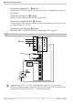
Configuration level 4.5.7 Continuous controller with position controller ( Cntr/ C.Fnc = 6 ) SP W INP.1 X Ycontinuous Ypid OUT.4 Master controller W Y.1 INP.2 X OUT.1 M Y.2 OUT.2 Position controller Basically, this controller function is a cascade. A slave controller with three-point stepping behaviour working with position feedback Yp as process value (INP2 or INP3) is added to a continuous controller. ConF / Cntr SP.Fn = 0 setpoint controller C.
Configuration level 4.5.8 Measured value output phys. quantity Out.1 mA / V phys. quantity Out.0 20mA 10V 0/4mA 0/2V 90...250VAC 24VUC } NL 1 2 1 2 3 3 4 5 6 7 8 9 OUT3 OUT4 10 11 12 U 13 14 15 4 5 6 7 8 9 10 11 12 13 14 U 15 (16) INP1 17 + ConF / Out.3 / 4: O.tYP = = = = Out.0 = 1 2 3 4 -1999...9999 Out.1 = -1999...9999 O.Src = 3 Configuration examples 54 Out.3/ 4 0...20mA continuous Out.3/ 4 4...20mA continuous Out.3/ 4 0...10V continuous Out.3/ 4 2...
Parameter setting level 5 Parameter setting level 5.1 Parameter survey g Inl.2 OuL.2 InH.2 OuH.2 tF.2 InL.3 OuL.3 InH.3 OuH.3 tF.3 E.tc End InL.1 OuL.1 InH.1 OuH.1 tF.1 Lim Limit value functions Input 3 Input 2 InP.3 SP.Lo SP.Hi SP.2 r.SP Input 1 SEtP Set-point and process value PAr.2 Pb12 Pb22 ti12 ti22 td12 td22 InP.2 Pb1 Pb2 ti1 ti2 td1 td2 t1 t2 SH Hys.l Hys.H d.SP tP tt Y.Lo Y.Hi Y2 Y0 Ym.H L.Ym E.H2O t.on t.off FH2 oFFS tEmp InP.1 Ì 2.
Parameter setting level 5.2 Parameters Cntr Name Pb1 Pb2 ti1 ti2 td1 td2 t1 t2 SH Hys.l Hys.H d.SP tP tt Y.Lo Y.Hi Y2 Y.0 Ym.H L.Ym E.H2O t.on t.oFF F.H2O oFFS tEmp Value range Description Default 1...9999 1 Proportional band 1 (heating) in phys. dimensions (e.g. °C) 100 1...9999 1 Proportional band 2 (cooling) in phys. dimensions (e.g. °C) 100 0,1...9999 Integral action time 1 (heating) [s] 180 0,1...9999 Integral action time 2 (cooling) [s] 180 0,1...
Parameter setting level PAr.2 Name Pb12 Pb22 Ti22 Ti12 Td12 Td22 Value range Description Default 1...9999 1 Proportional band 1 (heating) in phys. dimensions (e.g. °C), 100 2. parameter set 1...9999 1 Proportional band 2 (cooling) in phys. dimensions (e.g. °C), 100 2. parameter set 0,1...9999 Integral action time 2 (cooling) [s], 2. parameter set 10 0,1...9999 Integral action time 1 (heating) [s], 2. parameter set 10 0,1...9999 Derivative action time 1 (heating) [s], 2. parameter set 10 0,1...
Parameter setting level Name Value range Description -1999...9999 Filter time constant [s] t.F3 0...100 (°C) External cold-junction reference temperature (external TC) Etc.3 32...212 (°F Default 0 OFF Lim Name L.1 H.1 HYS.1 dEl.1 L.2 H.2 HYS.2 dEl.2 L.3 H.3 HYS.3 dEl.3 HC.A g Parameters Value range Description -1999...9999 Lower limit 1 -1999...9999 Upper limit 1 0...9999 Hysteresis limit 1 0...9999 Alarm delay from limit value 1 -1999...9999 Lower limit 2 -1999...9999 Upper limit 2 0...
Parameter setting level 5.3 Input scaling When using current, voltage or resistance signals as input variables for InP.1, InP.2 or/and InP.3 scaling of input and display values at parameter setting level is required. Specification of the input value for lower and higher scaling point is in the relevant electrical unit (mA / V / Ω). phys. quantity OuH.x phys. quantity mA / V OuL.x InL.x InH.x mA/V 5.3.1 Input Inp.1 and InP.3 g Parameters InL.x , OuL.x, InH.x and OuH.
Calibration level 6 Calibration level Measured value correction ( CAL) is only visible if ConF / InP.1 / Corr = 1 or 2 is chosen. The measured value can be matched in the calibration menu ( CAL). Two methods are available: Offset correction ( ConF/ InP.1 / Corr =1 ): display standard setting offset correction w possible on-line at the process OuL.1new OuL.1old InL.1 X 2-point correction ( ConF/ InP.
Calibration level Offset correction ( ConF/ InP.1 / Corr =1 ): r 1199 °C °F para func Ada Err 1200 r Ù r PArA 3 sec. Ì : SP.E SP.2 CAL r Ù r InP.1 r Ù r InL.1 r Ù r OuL.1 È r Ù Ì r End r Ù InL.1: The input value of the scaling point is displayed. The operator must wait, until the process is at rest. Subsequently, the operator acknowledges the input value by pressing key Ù. OuL.1: The display value of the scaling point is displayed. Before calibration, OuL.1 is equal to InL.1.
Calibration level 2-point correction ( ConF/ InP.1 / Corr = 2): 1199 °C °F 1200 r Ù r 3 sec. SP.E SP.2 PArA Ì r para func Ada Err ConF r Ì CAL r Ùr InP.1 r Ù r InL.1 r Ù È È Ì InL1 InP.2 OuL.1 Ù È Ì È rÙ Ì InH.1 r InP.3 Ù È InH.1 È Ì Ù OuH.1 Ù End È rÙ Ì InL.1: The input value of the lower scaling point is displayed. The operator must adjust the lower input value by means of a process value simulator and confirm the input value by pressing key Ù. OuL.
Special functions 7 Special functions 7.1 DAC®– motor actuator monitoring (Digital Actor Control DAC®) With all controllers with position feedback Yp, the motor actuator can be monitored for functional troubles. The DAC® function can be started by chosing the parameter C.Fnc = 5 or 6 at the configuration level ( ConF): w ConF / Cntr / C.Fnc = 5 3-point-stepping controller with position feedback Yp as potentiometer w ConF / Cntr / C.
Special functions Functioning of the DAC function No input filter should be defined for the Yp input ( PArA / InP.x / t.Fx = 0 ). Therewith no wrong detection of blocking or wrong method of operation can be recognized. The automatic calibration can be used with drives outfitted with spring assembly. Execution of the calibration: It is controlled if the mean alteration between two messurements is enough for the DAC monitoring.
Special functions 7.2 O2 measurement This function is available only on the instrument version with INP3. As the O2-measurement result range can extend over many decades, automatic display switch-over between “ % ” and “ppm“ was realized. The instantaneous unit is displayed in the lower line. With set-point changing via keys I or D, the unit of the set-point and of the other parameters is displayed. Lambda probes (λ probes) are used as sensors.
Special functions 7.2.2 Configuration: Oxygen measurement Oxygen measurement with heated lambda probe Controller r Process value processing r 7: O2 functions with constant probe temperature Cntr r C.tYP 7 O2-const Oxygen measurement with non-heated lambda probe Controller r Process value processing r O2 functions with measured probe temperature Cntr r C.tYP 8 O2+temp Input 1 r Function INP1 r 7: process value X1 InP.1 r 1.
Special functions 7.3 Linearization Linearization for inputs INP1 or INP3 Access to table “ Lin” is always with selection of sensor type S.TYP = 18: special thermocouple in INP1 or INP3, or with selection of linearization S.Lin 1: special linearization. Dependent of input type, the input signals are specified in µV or in Ohm dependent of input type. With up to 16 segment points, non-linear signals can be simulated or linearized. Every segment point comprises an input (In.1 … In.16) and an output (Ou.
Special functions 7.4 Loop alarm The loop alarm monitors the control loop for interruption (not with three-point stepping controller and not with signallers.) With parameter LP.AL switched to 1(= loop alarm active), an interruption of the control loop is detected, unless the process value reacts accordingly with Y=100% after elapse of 2xTi. The loop alarm shows that the control loop is interrupted. You should check heating or cooling circuit, sensor, controller and motor actuator.
Special functions 7.6 KS90-1 as Modbus master a This function is only selectable with BlueControl (engineering tool)! Additions othr Name MASt Cycl AdrO AdrU Numb (only visible with BlueControl!) Value range Description Default 0 Controller is used as Modbus master 0 Slave 1 Master 0...200 60 Cycle time [ms] for the Modbus master to transmit its data to the bus. 1...65535 1 Target address to which the with AdrU specified data is given out on the bus. 1...
BlueControl 8 BlueControl BlueControl is the projecting environment for the BluePort controller series of PMA. The following 3 versions with graded functionality are available: The mini version is - free of charge - at your disposal as download at PMA homepage www.pma-online.de or on the PMA-CD (please ask for). At the end of the installation the licence number has to be stated or DEMO mode must be chosen. At DEMO mode the licence number can be stated subsequently under Help r Licence r Change.
Versions 9 Versions Unit/f ront according to customer specification XX Accessories delivered with the unit Operating manual (if selected by the ordering code) w 2 fixing clamps w operating note in 12 languages Accessory equipment with ordering information Description Heating current transformer 50A AC PC-adaptor for the front-panel interface Standard rail adaptor Operating manual Operating manual Operating manual Interface description Modbus RTU Interface description Modbus RTU BlueControl (engineering
Technical data 10 Technical data Current and voltage signals INPUTS PROCESS VALUE INPUT INP1 Resolution: Decimal point: Dig. input filter: Scanning cycle: Measured value correction: > 14 bits 0 to 3 digits behind the decimal point adjustable 0,000...9999 s 100 ms 2-point or offset correction r Table 3 (page 76 ) Span start, end of span: Scaling: Linearization: Decimal point: Input circuit monitor: anywhere within measuring range selectable -1999...
Technical data CONTROL INPUTS DI2, DI3 (OPTION) Note: The functions of control input di2 on the analog If the relays operate external contactors, these card and of di2 on the options card are logically must be fitted with RC snubber circuits to manufacturer specifications to prevent excessive ORed. Configurable as direct or inverse switches or keys. switch-off voltage peaks. Optocoupler input for active triggering.
Technical data Humidity POWER SUPPLY Dependent of order: 75% yearly average, no condensation AC SUPPLY Shock and vibration Voltage: Frequency: Power consumption 90...260 V AC 48...62 Hz approx. 8,0 VA UNIVERSAL SUPPLY 24 V UC AC voltage: Frequency: DC voltage: Power consumption: 20,4...26,4 V AC 48...62 Hz 18...31 V DC approx..
Technical data cUL certification (Type 4x, indoor use) For compliance with cUL certificate,the following information must be taken into account: w Use only 60 / 75 or 75°C copper (Cu) wire. w Tighten the terminal- screws with a torque of 0,5 - 0,6 Nm Ambient temperature: ≤ 40°C Power supply: ≤ 250 V AC Electrical connections w flat-pin terminals 1 x 6,3mm or 2 x 2,8mm to DIN 46 244 or w screw terminals for 0,5 to 2,5mm² On instruments with screw terminals, the insulation must be stripped by min. 12 mm.
Technical data Table 1 Thermocouples measuring ranges Thermoelementtype L Fe-CuNi (DIN) J Fe-CuNi K NiCr-Ni N Nicrosil/Nisil S PtRh-Pt 10% R PtRh-Pt 13% T Cu-CuNi C W5%Re-W26%Re D W3%Re-W25%Re E NiCr-CuNi B * PtRh-Pt6% Measuring range -100...900°C -100...1200°C -100...1350°C -100...1300°C 0...1760°C 0...1760°C -200...400°C 0...2315°C 0...2315°C -100...1000°C 0(100)...1820°C * Specifications valid for 400°C -148...1652°F -148...2192°F -148...2462°F -148...2372°F 32...3200°F 32...3200°F -328...752°F 32...
Safety hints 11 Safety hints This unit was – built and tested in compliance with VDE 0411-1 / EN 61010-1 and – delivered in safe condition. – complies European guideline 89/336/EWG (EMC) and is provided with CE marking. – tested before delivery and passed the tests required by test schedule. – To maintain this condition and to ensure safe operation, the user must follow the hints and warnings given in this operating manual.
Safety hints MAINTENANCE, REPAIR AND MODIFICATION The units do not need particular maintenance. Warning a When opening the units, or when removing covers or components, live parts and terminals may be exposed. Before starting this work, the unit must be disconnected completely. After completing this work, re-shut the unit and re-fit all covers and components. Check if specifications on the type label must be changed and correct them, if necessary.
Safety hints 11.1 Resetting to factory setting, or to a customer-specific data set In case of faultyconfiguration, the device can be reset to a default condition. Unless changed, this basic setting is the manufacturer-specific controller default setting. However, this setting may have been changed by means of the BlueControl® software. This is recommendable e.g. when completing commissioning in order to cancel accidental alteration easily.
Safety hints 1 2 3 4 Safety switches closed open open open Levels Password any free free min. 1 disabled any none defind any Instrument reaction after confirming ”YES” by pressing Ù always factory reset Factory reset without prompt for the password Factory reset after entry of the correct pass number Factory reset is omitted g Timeout Unless a key is pressed during 10 seconds, a timeout occurs and the instruments starts without copying the default data.
Index Water cooling non-linear . . . . . . 45 Current signal measuring range . . . . 73 0-9 2-point correction. . . . . . . . . . . . 61 D DAC . . . . . . . . . . . . . . . . 64 - 65 A Alarm handling . . . . . . . . . . 26 - 27 B Digital inputs di1, di2, di3 Configuration . . . . . . . . . . . . 38 Technical data . . . . . . . . . . . . 73 Bargraph . . . . . . . . . . . . . . . . 11 E BlueControl. . . . . . . . . . . . . . . 71 Environmental conditions . . . . . . .
SP.2 - LED. . . . . . . . . . . . . . 11 SP.x - LED. . . . . . . . . . . . . . 11 Linearization . . . . . . . . . . . . . . 68 R M Resistance thermometer measuring range . . . . . . . . . . . . . . . . . . . . . 73 Mainenance manager . . . . . . . 13 - 15 Ramp . . . . . . . . . . . . . . . . . . 43 Resetting to factory setting . . . . . . . 78 Manual tuning . . . . . . . . . . . . . 24 S Modbus master . . . . . . . . . . . . . 70 Safety hints . . . . . . . . . . . . 77 - 78 Mounting. . . . . . . .
2 Subject to alterations without notice Änderungen vorbehalten Sous réserve de toutes modifications © PMA Prozeß- und Maschinen-Automation GmbH P.O.B.