
Instruction Manual


Electrical connection
9499-040-93811 / 59537-1 Page 8 of 88 Pro-16
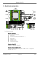
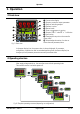
2. Electrical connection
Fig. 4: Electrical connection
Connection of input INP1
Input for variable x1 (process value)
a thermocouple
b resistance thermometer (Pt100/ Pt1000/ KTY/ ...)
c potentiometer
d voltage (0/2...10V)
e current (0/4...20mA)
f Transmitter Power Supply
Connection of input INP2
current (0/4…20mA and 0…30mA AC).
Connection of inputs di1/di2/di3 and di4
Digital inputs for switching functions, e.g. SP and SP.2/SP.e or programmer
Run/Stop/Reset.