Pro-16 Pro-16 Industrial Controller User Guide Manual Part number: 59537-1 October 2013
© West Control Solutions All rights reserved. No part of this document may be reproduced or published in any form or by any means without prior written permission from the copyright owner. A publication of West Control Solutions P.O.
Table of contents 1. Mounting 6 2. Electrical connection 8 3. Operation 9 4. 3.1 3.2 Front view Operating structure 3.2.1 Operating Level 3.3 Behaviour after power-on 3.4 Operating level 3.5 Errorlist / Maintenance Manager 3.5.1 Error-List: 3.5.2 Error-Status (Self-tuning) 3.6 Function level 3.7 Self-tuning 3.7.1 Preparation before self-tuning 3.7.2 Optimization after start-up or at the set-point 3.7.3 Selecting the method ( ConF/ Cntr/ tunE) 3.7.4 Step attempt after start-up 3.7.
.4 5. Configuration examples 4.4.1 On-Off controller / Signaller (inverse) 4.4.2 2-point and continuous controller (inverse) 4.4.3 3-point and continuous controller 4.4.4 3-point stepping controller (relay & relay) 4.4.5 - Y - Off controller / 2-point controller with pre-contact 4.4.6 KS 20-1 with measured value output 46 46 47 48 49 50 51 Parameter-Level 52 5.1 5.2 52 53 Parameter-Overview Parameter 6. Input scaling 57 7. Calibration level 58 8. Programmer 61 8.
12. Technical Data 81 13. Safety notes 84 13.
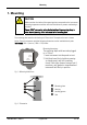
Mounting 1. Mounting CAUTION Make sure that the inside of the mounting plate corresponds to the instrument operating temperature and that sufficient ventilation to prevent overheating is provided. Please, DON’T remove the safety device/sealing of the mounting plate, in order to avoid jamming of the instrument in the mounting plate. The mounting plate must be solid and up to 6.0 mm thick. The required cut-out is shown below.
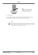
Mounting Slip the mounting clip from behind onto the housing until the spring tab snaps in the latch. Fig. 3: Mounting clip After installing the instrument in the mounting plate, it may be removed from its housing, if necessary (see the information on fitting and removing the optional modules). NOTE! g 9499-040-93811 / 59537-1 The flanges of the mounting clip lock in position on both sides or on the top and bottom side of the instrument housing.
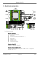
Electrical connection 2. Electrical connection Fig. 4: Electrical connection Connection of input INP1 Input for variable x1 (process value) a thermocouple b resistance thermometer (Pt100/ Pt1000/ KTY/ ...) c potentiometer d voltage (0/2...10V) e current (0/4...20mA) f Transmitter Power Supply Connection of input INP2 current (0/4…20mA and 0…30mA AC). Connection of inputs di1/di2/di3 and di4 Digital inputs for switching functions, e.g. SP and SP.2/SP.e or programmer Run/Stop/Reset.
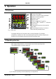
Operation 3. Operation 3.1 Front view 1 Process value display 2 Set-point, controller output, parameter 3 Status of switching outputs 4 Gradient is active 5 Manual mode 6 Timer or programmer is running 7 Set-point SP.2 oder SP.e is effective 8 Function key 9 Changing the set-point or the controller output value 0 Acknowledges alteration of a value or shows the next parameter/value Fig. 5: Front view In the upper display line, the process value is always displayed.
Operation The setting in the function level or in BlueControl® (engineering tool), individual layers can be locked or made accessible by entering the password in. Individual parameters accessible without password must be copied to the extended operating level via BlueControl®. When supplied, all levels are fully accessible, Password PASS = OFF 3.2.1 Operating Level See also chapter 3.4 Operating level And chapter 3.6 Function level 3.
Operation 3.4 Operating level The operating level comprises two views for setpoint and controller output value. The operating level can be enhanced with two levels Extended operating level Function level (see chapter 3.6) The content of the extended operating level and the function level is determined by means of BlueControl (engineering tool). Parameters which are used frequently or the display of which is important can be copied to the extended operating level. Fig.
Operation 3.5 Errorlist / Maintenance Manager The error list is visible only if an error entry is present. An active entry in the error list is displayed by a red/green blinking 2nd line and status LED’s in the display. Err-Status Signification Proceed as follows 2. line existing blinks red error - determine the error type in the error list via the error number - remove error .. is red error removed - Acknowledge the alarm in the error list by pressing key È - or È - The alarm entry is deleted. ..
Operation circuit at controller off state relay - SSR defective Loop Control loop alarm - Input signal defective or not connected correctly - Check heating or cooling circuit - Output not connected correctly - Check controller and switching device - Check sensor and replace it, if necessary AdA.H Self-tuning heating See Self-tuning heating see Self-tuning heating error alarm (ADAH) error status status Ada.
Operation 3.6 Function level Switching functions via è key. The function level serves for the enhanced operation of the device. You can switch functions such as manual / automatic, Sollwert/Sp.2/Sp.E, ... via the operation level on the controller are performed.
Operation 3.7 Self-tuning (automatic adaption of control parameters) For determination of optimum process parameters, self-tuning is possible. After starting by the operator, the controller makes an adaptation attempt, whereby the process characteristics are used to calculate the parameters for fast line-out to the set-point without overshoot. The following parameters are optimized when self-tuning: Parameter set 1: Pb1 Proportional band 1 (heating) in engineering units [e.g. °C] 3.7.
Operation 3.7.2 Optimization after start-up or at the set-point There are two methods of optimization; either after start-up or at the set-point. As control parameters are always optimal only for a limited process range, various methods can be selected dependent of requirements. If the process behavior is very different after start-up and directly at the set-point, parameter sets 1 and 2 can be optimized using different methods.
Operation 3.7.4 Step attempt after start-up Condition: or - tunE = 0 and sufficient set-point reserve provided - tunE = 2 The controller outputs 0% correcting variable or Y.Lo and waits, until the process is at rest (see start-conditions on page 15). Subsequently, a correcting variable step change to 100% or Y.Hi is output. The controller attempts to calculate the optimum control parameters from the process response.
Operation with active gradient function ( PArA/ SETP/ r.SP OFF), the set-point gradient is started from the process value and there isn't a sufficient set-point reserve. Optimization-at-the-set-point procedure: The controller uses its instantaneous parameters for control to the set-point. In stable condition, the controller makes a pulse attempt. This pulse reduces the correcting variable by max. 20% 1, to generate a slight process value undershoot.
Operation Optimization at the set-point for 3-point stepping controller As position feedback is not provided, the controller calculates the actuator position internally by adjusting an integrator with the adjusted actuator travel time. For this reason, precise entry of the actuator travel time (tt), as time between stops is highly important. Due to position simulation, the controller knows whether an increased or reduced pulse must be output.
Operation 3.7.7 Self-tuning start The operator can start self-tuning at any time. For this, keys Ù and È must be pressed simultaneously. With blinking in the second row the active adaptation is displayed Ad:PIR. The controller outputs 0%, waits until the process is at rest and starts selftuning: Ad:Stp The self-tuning attempt is started when the following prerequisite is met: The difference between process value i set-point must be 10% of the set-point range ( SP.Hi - SP.
Operation Start: heating power switched on Heating power Y is switched off (1). When the change of process value X was constant during one minute (2), the power is switched on (3). At the reversal point, the self-tuning attempt is finished and the new parameter are used for controlling to set-point W. Start: heating power switched off The controller waits 1,5 minutes (1). Heating power Y is switched on (2).
Operation During phase 3, heating and cooling are done simultaneously! 3-point-stepping controller After the start (1) the controller closes the actuator (2 Out.2). When the difference between process value and set-point is big enough (3), the changing of the process value is monitored for 1 min. (4). Afterwards the actuator is opened (5 Out.1). If the reversal point is reached (6) or there are made enough measurements, the parameters are detected and are adopted. W X t 1 min t 1 2 3 4 5 6 3.
Operation Parameter adjustment effects Parameter Control Stabilized of disturbances Pb1 higher increased damping slower stabilized lower reduced damping td1 higher reduced damping lower increased damping ti1 higher increased damping lower reduced damping faster stabilized faster response to disturbances slower response to disturbances slower stabilized faster stabilized Start-up behaviour slower reduction of duty cycle faster reduction of duty cycle faster reduction of duty cycle slower reduction of d
Operation 3.10 Alarm handling Max. three alarms can be configured and assigned to the individual outputs. Generally, outputs OuT.1... OuT.6 can be used each for alarm signalling. If more than one signal is linked to one output the signals are OR linked. Each of the 3 limit values Lim.1 … Lim.3 has 2 trigger points H.x (Max) and L.x (Min), which can be switched off individually (parameter = “OFF”). Switching difference HYS.x of each limit value is adjustable. Ü Operaing principle absolute alarm L.
Operation The following variables are available ( ConF / Lim / Src .x ): Variable (Src .x) Remark Process value Control deviation xw Process value - effective set-point. The effective set-point Weff is used. E.g with a ramp, this is the changing set-point rather than the target set-point. Control deviation xw + The alarm output is suppressed after switch-on or suppression after start- after a set-point change, until the process value is up or set-point change within the limits for the first time.
Configuration level 4. Configuration level 4.1 Configuration overview SP.Fn t.bAS StYP Ù I.Fnc Fnc.1 O.tYP O.Act L_r bAud SP.2 Addr SP.E PrtY Y.2 dELY y.E Unit mAn dP Y.2 mAn Src.2 Y.2 Lim.1 C.Act Fnc.3 Lim.1 Lim.2 FAIL Src.3 Lim.2 Lim.3 rnG.L HC.AL Lim.3 LP.AL C.oFF Led rnG.H LP.AL LP.AL HC.AL Err.r C.dEl See output 2 Fnc.2 Y.1 See output 1 Src.1 O.Act Y.1 Corr See output 2 S.Lin StYP C.Fnc See output 2 b.ti Sp2C HC.AL HC.SC boos CyCL HC.SC TimE Pid.
Configuration level Adjustment: To access the configuration level, press the key Ù for 3 seconds and then the key Ì to select the ConF-Menu item. Press Ù to confirm. If the password function is activated, a prompt for PASS is displayed. The configuration values can be adjusted using the ÌÈ keys. Press the Ù key to save the value. The next configuration value is shown.
Configuration level / Y / Off, or 2-point controller with partial/full load switchover 3 2 x PID (3-point and continuous) 4 3-point stepping controller mAn Manual operation permitted 0 0 no 1 yes (see also LOGI/ mAn) C.Act Method of controller operation 0 0 inverse, e.g. heatingWith decreasing process value, the correcting variable is increased, with increasing process value, the correcting variable is reduced. 1 direct, e.g.
Configuration tunE 0 1 2 Strt 0 1 Adt0 0 1 level Auto-tuning at start-up At start-up with step function At start-up with impulse function. Setting for fast controlled systems (e.g.
Configuration 23 30 40 S.Lin 0 1 Corr 0 1 2 3 fAI1 0 1 level special 0...4500 Ohm (pre-defined as KTY11-6) 0...20mA / 4...20mA Scaling is required (see chp. page 57) 0...10V / 2...10V Scaling is required (see chp. page 57) Linearization (only at S.tYP = 23 (KTY 11-6), 30 (0..20mA) and 40 (0..10V) adjustable) (see page 74) Without linearization Linearization to specification. Creation of linearization table with BlueControl (engineering tool) possible.
Configuration level Lim Name Fnc.1 Fnc.2 Fnc.3 Src.1 Src.2 Src.3 HC.AL LP.AL Hour Swit Value range Description Default Function of limit 1/2/3 1 switched off measured value monitoring Measured value monitoring + alarm status storage. A stored limit value can be reset via error list, è-key, or a digital input ( -> LOGI/ Err.
Configuration 4 5 O.Act 0 1 Y.1 Y.2 Lim.1 Lim.2 Lim.3 0 1 0 1 LP.AL 0 1 HC.AL 0 1 HC.SC 0 1 timE 0 1 t.End 0 1 P.End 0 1 FAi.1 FAi.2 PrG.1 PrG.2 PrG.3 PrG.4 CALL 9499-040-93811 / 59537-1 0 1 0 1 level 2...10 V continuous (only visible with current/logic/voltage) transmitter supply (only visible without OPTION) Method of operation of output OUT (only visible when O.TYP=0) direct / normally open inverse / normally closed Controller output Y1/Y2 (only visible when O.
Configuration level 0 not active 1 active Out.0 -1999...9999 Scaling of the analog output for 0% (0/4mA or 0/2V, only visible when O.TYP=1..5) Out.1 -1999...9999 Scaling of the analog output for 100% (20mA or 10V, only visible when O.TYP=1..5) O.Src Signal source of the analog output OUT3 (only visible when O.TYP=1..
Configuration 0 1 0 1 not active active Solid state relay (SSR) short circuit signal (only visible when O.TYP=0) not active active Timer active (only visible when O.TYP=0) not active active Timer End (only visible when O.TYP=0) not active active Programmer end signal (only visible when O.TYP=0) not active active INP1/ INP2 error (only visible when O.TYP=0) not active active Program track 1 to 4 (only visible when O.TYP=0) not active active 0 0 1 0 0 1 Operator call (only visible when O.
Configuration level LOGI Name Value range L_r 0 1 2 3 4 5 6 7 8 9 SP.2 0 2 3 4 5 6 7 8 9 SP.E 0 1 2 3 4 5 6 7 8 9 Y2 0 2 9499-040-93811 / 59537-1 Description Local / Remote switching (Remote: adjusting of all values by front keys is blocked) no function (switch-over via interface is possible) active DI1 Di 2 DI3 (only visible with OPTION) DI4 (only visible with OPTION) è -Key function (see chapter 3.6 page 14) Limit 1 Limit 2 Limit 3 Switching to second setpoint SP.
Configuration 3 4 5 6 7 Di 2 DI3 (only visible with OPTION) DI4 (only visible with OPTION) è -Key function (see chapter 3.6 page 14) Limit 1 8 9 Limit 2 Limit 3 YE switch-over No function (switch-over via interface is possible) always active DI1 switches Di 2 DI3 (only visible with OPTION) DI4 (only visible with OPTION) è -Key function (see chapter 3.
Configuration 8 9 Err.r 0 2 3 4 5 6 7 8 9 booS 0 2 3 4 5 6 7 8 9 Pid.2 0 2 3 4 5 6 7 8 9 P.run 0 2 3 4 5 9499-040-93811 / 59537-1 level Limit 2 Limit 3 Reset of all error list entries no function (switch-over via interface is possible) DI1 Di 2 DI3 (only visible with OPTION) DI4 (only visible with OPTION) è -Key function (see chapter 3.6 page 14) Limit 1 Limit 2 Limit 3 Boost function: setpoint increases by SP.bo for the time t.
Configuration 6 7 8 9 è -Key function (see chapter 3.6 page 14) Limit 1 Limit 2 Limit 3 Programmer Run/Stop (see page ) 0 2 3 4 5 6 7 8 9 no function (switch-over via interface is possible) DI1 Di 2 DI3 (only visible with OPTION) DI4 (only visible with OPTION) è -Key function (see chapter 3.
Configuration 1 2 dP 0 1 2 3 0..200 C.dEl FrEq MASt Cycl Adr0 AdrU Numb ICof IAda IExo ILat pTmp level °C °F Decimal point (max. number of digits behind the decimal point) no digit behind the decimal point 1 digit behind the decimal point 2 digits behind the decimal point 3 digits behind the decimal point Modem delay [ms] Additional delay time before the received message is evaluated in Modbus. This time is needed by the modem if messages are not transferred continuously.
Configuration pPre 0 1 pRun 0 1 pCom Pass IPar 0 1 OFF...9999 0 1 ICnf 0 1 ICal 0 1 F.Coff 0 1 D2.
Configuration level BlueControl - the engineering tool for the BluePort controller series For facilitating configuration and parameter setting of the KS20-1 an engineering tool with different functionality levels is available : Accessory equipment with ordering information. In addition to configuration and parameter setting, BlueControl is used for data acquisition and offers long-term storage and print functions.
Configuration level 4.3 Set-point processing The set-point processing structure is shown in the following picture: 4.3.1 Set-point gradient / ramp To prevent set-point step changes, parameter r set-point r r.SP can be adjusted to a maximum rate of change. This gradient is effective in positive and negative direction.. With parameter r.SP set to OFF (default), the gradient is switched off and set-point changes are realized directly. (for parameter: see page 55) 4.3.
Configuration level short on and off pulses. The shortest pulses result from ¼ x t1 or ¼ x t2. The characteristic curve is also called “bath tub curve”. 4.3.4 Parameters to be adjusted t1 : min. cycle time 1 (heating) [s] ( PArA/ Cntr) min. cycle time 2 (cooling) [s] t2 : Switching attitude linear ( CyCl=1) For heating (Y1), the standard method (see chapter 4.3.3) is used. For cooling (Y2), a special algorithm for cooling with water is used.
Configuration 4.3.5 level Switching attitude non-linear ( CyCl= 2 ) With this method, the cooling power is normally much higher than the heating power, i.e. the effect on the behaviour during transition from heating to cooling may be negative. The cooling curve ensures that the control intervention with 0 to -70% correcting variable is very weak. Moreover, the correcting variable increases very quickly to max. possible cooling. Parameter F.H2O can be used for changing the characteristic curve.
Configuration 4.3.6 level Heating and cooling with constant period ( CyCl=3 ) The adjusted cycle times t1 and t2 are met in the overall output range . To prevent unreasonably short pulses, parameter tp is used for adjusting the shortest pulse duration. With small correcting values which require a pulse shorter than the value adjusted in tp, this pulse is suppressed. However, the controller stores the pulse and totalizes further pulses, until a pulse of duration tp can be output.
Configuration level 4.4 Configuration examples 4.4.1 On-Off controller / Signaller (inverse) ConF/Cntr: SP.Fn C.Fnc C.Act ConF/Out.1: O.Act Y.1 PArA/Cntr: HYS.L PArA/Cntr: HYS.H PArA/SEtP: SP.LO SP.Hi g 9499-040-93811 / 59537-1 =0 =0 =0 =0 =1 = 0...9999 = 0...9999 = -1999...9999 = -1999...9999 set-point /cascade controller signaller with one output inverse output action (e.g. heating applications) output action Out.
Configuration 4.4.2 level 2-point and continuous controller (inverse) ConF/Cntr SP.Fn C.Fnc C.Act ConF/Out.1: O.Act Y.1 ConF/Out.3: O.tYP Out.0 Out.1 O.Src PArA/Cntr: Pb1 ti1 td1 t1 PArA/SEtP: SP.LO SP.Hi g 9499-040-93811 / 59537-1 =0 =1 =0 =0 =1 =1/2 = -1999...9999 = -1999...9999 = 1 = 1...9999 set-point / cascade controller 2-point and continuous controller (PID) inverse action (e.g. heating applications) action Out.1 direct control output Y1 active Out.
Configuration 4.4.3 level 3-point and continuous controller ConF/Cntr: SP.Fn = 0 set-point / cascade controller C.Fnc = 3 3-point controller (2xPID) C.Act = 0 action inverse (e.g. heating applications) ConF/Out.1: O.Act = 0 action Out.1 direct Y.1 =1 control output Y1 active Y.2 =0 control output Y2 not active ConF/Out.2: O.Act = 0 action Out.2 direct Y.1 =0 control output Y1 not active Y.2 =1 control output Y2 active Conf/Out.3: O.typ = 1 / 2 0 ... 20 mA continuous. / 4 ...
Configuration 4.4.4 level 3-point stepping controller (relay & relay) SP.Fn =0 set-point / cascade controller C.Fnc =4 C.Act =0 3-point stepping controller inverse action (e.g. heating applications) action Out.1 direct ConF/Out.1: O.Act =0 control output Y1 active Y.1 =1 control output Y2 not active Y.2 =0 action Out.2 direct =0 control output Y1 not active Y.1 =0 control output Y2 active Y.2 =1 Pb1 = 1...9999 proportional band 1 (heating) in units of phys. quantity (e.g.
Configuration 4.4.5 level - Y - Off controller / 2-point controller with pre-contact ConF/Cntr: SP.Fn = 0 set-point / cascade controller C.Fnc = 2 D -Y-Off controller C.Act = 0 inverse action (e.g. heating applications) ConF/Out.1: O.Act = 0 action Out.1 direct Y.1 = 1 control output Y1 active Y.2 = 0 control output Y2 not active ConF/Out.2: O.Act = 0 PArA/Cntr: PArA/SEtP: action Out.2 direct Y.1 = 0 control output Y1 not active Y.2 = 1 control output Y2 active Pb1 = 1...
Configuration 4.4.6 level KS 20-1 with measured value output Example: KS20-10H-LR000-000 ConF/Out.3:O.tYP = 1 Out.3 0...20mA continuous = 2 Out.3 4...20mA continuous = 3 Out.3 0...10V continuous = 4 Out.3 2...10V continuous Out.0 = -1999...9999 Scaling Out.3 for 0/4mA e.g. 0/2V Out.1 = -1999...9999 Scaling Out.3 for 20mA e.g. 10V O.Src = 3 9499-040-93811 / 59537-1 Signal source for Out.
Parameter-Level 5. Parameter-Level 5.1 Parameter-Overview Ù Pb1 Pb12 SP.Lo InL.1 Inl.2 L.1 Pb2 Pb22 SP.Hi OuL.1 OuL.2 H.1 ti1 ti12 SP.2 InH.1 InH.2 HYS.1 ti2 ti22 r.SP OuH.1 OuH.2 dEl.1 td1 td12 t.SP tF.1 td2 td22 SP.bo H.2 t1 t.bo HYS.2 t2 Y.St dEl.2 SH SP.St L.3 Hys.l t.St H.3 End ProG Programmer Lim Limit value functions InP.2 Input 2 InP.1 Input 1 SEtP Set-point and process value PAr.2 2.
Parameter-Level Adjustment: To access the parameter level, press the key Ù for 3 seconds and confirm using the Ù -key subsequently. If the password function is activated, the prompt for the PASS is displayed The parameters can be adjusted using the ÌÈ - keys. Press the Ù - key to change to the next parameter. After the last parameter of a group, donE is displayed and followed by automatic changing to the next group g g g Return to the beginning of a group, by pressing the Ù key for 3 sec.
Parameter-Level HYS.L 0...9999 Switching difference Low signaller [engineering unit] 1 HYS.H 0...9999 Switching difference High signaller [engineering unit] 1 d.SP tP -1999...9999 Trigger point seperation for additional contact / Y / Off [phys. dimensions] 0,1...9999 Minimum impulse [s] tt 3...9999 100 OFF Motor travel time [s] 60 Y2 -100...100 2. correcting variable 0 Y.Lo -105...105 Lower output limit [%] 0 Y.Hi -105...105 Upper output limit [%] 100 Y.0 -100...
Parameter-Level SEtP Name Value range Description Default SP.LO -1999...9999 Set-point limit low for Weff 0 SP.Hi -1999...9999 Set-point limit high for Weff 900 SP.2 -1999...9999 Set-point 2 r.SP SP.bo OFF/0,01...9999 Set-point gradient [/min] -1999...9999 t.bo 0...9999 Y.St -120...120 SP.St t.St SP g -1999...9999 0...9999 -1999...
Parameter-Level Lim Name Value range Description Default L.1 -1999...9999 Lower limit 1 -10 H.1 -1999...9999 Upper limit 1 10 HYS.1 0...9999 Hysteresis limit 1 1 dEL.1 0...9999 Alarm delay from limit value 1 [s] 0 L.2 -1999...9999 Lower limit 2 OFF H.2 -1999...9999 Upper limit 2 OFF HYS.2 0...9999 Hysteresis limit 2 1 dEL.2 0...9999 Alarm delay from limit value 2 [s] 0 L.3 -1999...9999 Lower limit 3 OFF H.3 -1999...9999 Upper limit 3 OFF HYS.3 0...
Input scaling 6. Input scaling When using current or voltage signals as input variables for InP.1 or InP.2, scaling of input and display values at parameter setting level is required. Specification of the input value for lower and higher scaling point is in the relevant electrical unit (mA/ V). Input Inp.1 g Parameter InL.1 , OuL.1, InH.1 und OuH.1 are only visible if ConF / InP.1 / Corr = 3 is chosen. S.tYP Input signal 30 (0...20mA) 0 … 20 mA DC 0 -1999...9999 20 -1999...
Calibration level 7. Calibration level g Measured value correction ( CAL) is visible only if ConF / InP.1 / Corr = 1 or 2 is selected. To access the calibration level, press the key Ù for 3 seconds and then the key Ì to select the CAL-Menu item. Press Ù to confirm. If the password function is activated, a prompt for the PASS is displayed. In the calibration menu ( CAL), the measured value can be adapted. Two methods are available : Offset correction ( ConF/ InP.1 / Corr =1 ): InL.1: 0.
Calibration level Offset correction ( ConF/ InP.1 / Corr =1 ): possible on-line at the process 2-point correction ( ConF/ InP.1 / Corr = 2): InL.1: 0.0 The input value of the lower scaling point is displayed. The operator must adjust the lower input value by means of a process value simulator and confirm the input value by pressing key Ù. OuL.1: 0.0 The display value of the lower scaling point is displayed. Before calibration, OuL.1 is equal to InL.1.
Calibration level InH.1: 0.0 The input value of the upper scaling point is displayed. The operator must adjust the upper input value by means of the process value simulator and confirm the input value by pressing key Ù. OuH.1: 0.0 The display value of the upper scaling point is displayed. Before calibration OuH.1 is equal to InH.1.The operator can correct the upper display value by pressing keys ÌÈ Subsequently, he confirms the display value by pressing key Ù. 2-point correction ( ConF/ InP.
Programmer 8. Programmer 8.1 Operation Programmer operation (run/stop, preset and reset) is via è-Key-Menu, digital inputs or interface (BlueControl, superordinate visualization, ...). Operating via front keys The function key è opens the function menu of the programmer. By using the arrow buttons select a function. In order to exit the screen, either press the è key, or it will automatically exit after 30 seconds.
Programmer 8.1.1 Programmer display Programmer is in reset and the internal controller setpoint is effective. Segment or program number and OFF are displayed (configurable with BlueControl: Configuration r Other r PDis3). Programmer running (run LED is lit). Segment or program number, segment type (/ rising; \ falling; - hold) and program/segment rest time or runtime are displayed (configurable with BlueControl: Configuration r Other r PDis3). Program end was reached.
Programmer End segment The last segment in a program is the end segment. When reaching the end segment, output of the setpoint output last is continued. Waiting and operator call All segment types except end segment can be combined with ”Wait at the end and operator call”. If a segment with combination ”wait” was configured, the programmer goes to stop mode at the segment end (run LED is off). Now, the programmer can be restarted by pressing the start/stop key (>3s), via interface or digital input.
Programmer 8.1.4 Search run at programmer start The programmer starts the first segment at the actual process value (search run). This may change the effective runtime of the first segment. 8.1.5 Behaviour after mains recovery or sensor error Mains recovery After power recovery, the last program set-points and the time elapsed so far are not available any more. Therefore, the programmer is reset in this case.
Programmer 8.2 Parameter overview È Ì prg src b.lo dst End Copy Copying programs Programmer level Edit Editing programs Prog b.hi d.00 type sp pt d.out ··· type sp pt tout Setting: The parameters can be set by means of keys ÌÈ Transition to the next parameter is by pressing key Ù After the last parameter of a group, donE is displayed and an automatic transition the next group occurs g 9499-040-93811 / 59537-1 Return to the start of a group is by pressing key Ù during 3 sec. .
Programmer 8.3 Parameter ProG Name Value Range b.Lo b.Hi d.00 0...9999 0...9999 0 1 2 3 4 5 6 7 8 9 10 11 12 13 14 15 tYPE SP Pt d.Out tYPE 0 1 2 3 4 5 6 7 8 -1999...9999 0...9999 9499-040-93811 / 59537-1 Description Bandwidth lower limit Bandwidth upper limit Resetvalue of control track 1 ...
Programmer Name Value Range SP Pt d.Out tYPE SP Pt d.Out tYPE SP Pt d.Out tYPE SP Pt d.Out tYPE SP Pt d.Out tYPE SP Pt d.Out tYPE SP Pt d.Out • • • tYPE Pt d.Out tYPE SP Pt d.Out -1999...9999 0...9999 -1999...9999 0...9999 -1999...9999 0...9999 -1999...9999 0...9999 -1999...9999 0...9999 -1999...9999 Description segment end set-point 2 segment time/-gradient 2 control track 1...4 - 2 (see parameter d.
Programmer 8.4 Programmer description 8.4.
Programmer 8.4.2 Programmer set-up: The instrument is factory-configured as a program controller. The following settings must be checked: Set-point function For using the controller as a programmer, select parameter SP.Fn = 1 / 9 in the ConF menu (r page 27). Time base The time base can be set to hours:minutes or minutes:seconds in the ConF menu; parameter t.bAS (r page 29).
Programmer Start by setting the bandwidth high and low (b.Lo; b.Hi) limits and the control output reset value (d.00) for the selected program. The bandwidth is valid for all. g Configuration parameter pCom (r page 40) can be used for display suppression of bandwidth parameters and control output reset value, which, however, remains valid. Select the segment number (SEg; Segm.-No) for the segment which is to be edited.
Special functions 9. Special functions 9.1 Start-up circuit The start-up circuit is a special function for temperature control, e.g. hot runner control. Highperformance heating cartridges with magnesium oxyde insulation material must be heated slowly to remove moisture and prevent destruction. Operating principle: 1 After switching on the supply voltage, stabilised to the start-up set-point SP.St is using a maximum start-up correcting value of Y.St. 2 The start-up holding time t.
Special functions 9.2 Boost function The boost function causes temporary increase of the set-point, e.g. for removing "frozen" material from clogged die nozzles with hot-runner control. If configured (r ConF/ LOGI/ booS), the boost function can be started via digital input di1/2/3, with the function key on the instrument front panel or via the interface (OPTION). The set-point increase around boost set-point PArA /SEtP/SP.
Special functions 9.3 KS 20-1 as Modbus-Master This function is only selectable with the BlueControl engineering tool Additions othr (only visible with BlueControl!) Name Value range MASt Description Controller is used as Modbus master 0 Slave 1 Master Cycl 0...200 AdrO 1...65535 AdrU 1...65535 Numb 0...100 Cycle time [ms] for the Modbus master to transmit its data to the bus. Target address to which the with AdrU specified data is given out on the bus.
Special functions 9.4 Linearization Linearization for input INP1 The "Lin" parameter is valid if the following condition is met: S.tYP and = 18 (Special linearization) = 23 (KTY11-6) = 30 (Current) = 40 (Voltage) S.Lin ------= 1: Special linearization = 1: Special linearization Dependent of input type, the input signals are specified in μV, [, mA or Volt dependent of input type. With up to 16 segment points, non-linear signals can be simulated or linearized.
Special functions 9.5 Timer 9.5.1 Setting up the timer Operating modes 6 different timer modes are available to the user. The relevant timer mode can be set via parameter SP.Fn in the Conf menu (r page 27). Mode 1 (–) After timer start, control is to the adjusted set-point . The timer (t.SP) runs as soon as the process value enters or leaves the band around the set-point (x = SP _ b.ti). After timer elapse, the controller returns to Y2.
Special functions Tolerance band Timer modes 1,2 and 6 are provided with a freely adjustable tolerance band. The tolerance band around the set-point can be adjusted via parameter b.ti in the Conf menu (x = SP.2 _ b.ti) (r page 27). Timer start Various procedures for starting the timer are possible: LOGI Start via 1 Y2 SP.2 = = Mode 1 2 3 4 5 d d d d d 2 x d d d d d 3 x d d d d d 4 x d d d d d 5 x w w w w w SP / SP.
Special 9.5.3 functions Starting the timer Dependent of configuration, the timer start is as follows: by a positive activation at one of digital inputs di1..3 by switching on the manual mode via è - key by switching on the controller (power On) by changing the timer run-time t.
Ordering 10.
BlueControl® 11. BlueControl® BlueControl is the projection environment for the BluePort® controller series of PMA.
BlueControl® 11.1 Configuration Port The BluePort® interface is used to connect to the PC based BlueControl® configuration tool. The PC is connected via a mini USB adapter to the device. The connector is located on top of the housing (see picture) a This is not a USB interface.
Technical Data 12. Technical Data INPUTS Process value input INP1 Resolution: Decimal point: > 14 Bit (20.000 steps) 0 to 3 digits behind the decimal point Dig. input filter: adjustable 0,0...100,0 s Scanning cycle: 100 ms Measured value correction: 2-point or offset correction Thermocouples rTable 1 (page 83) Input resistance: 1 M Effect of source resistance: 1 V/ Cold-junction compensation: intern max.
Technical Data Linear DC output option 1 & 3 Current output ENVIRONMENTAL CONDITIONS Protection modes 0/4mA...20 mA, configurable. Signal range: 0...approx. 22 mA Load: ≤ 500 Ω Load effect: none Resolution: (0.1%) Error: (0.2%) Front panel: Housing: Terminals: Permissible temperatures For specified accuracy: Warm-up time: Temperature effect: For storage: 0-10 V Signal range: Load: Resolution: Error: 0...11 V ≥ 2K Ω ≤ 0.1 % ≤ 0.2 % Protocol: 0...60°C 15 minutes < 100ppm/K -20...
Technical Data Table 1 Thermocouples measuring ranges Thermocouple type Measuring range Accuracy Resolution (Ø) L Fe-CuNi (DIN) -100...900°C -148...1652°F ß 2K 0,1 K J Fe-CuNi -100...1200°C -148...2192°F ß 2K 0,1 K K NiCr-Ni -100...1350°C -148...2462°F ß 2K 0,2 K N Nicrosil/Nisil -100...1300°C -148...2372°F ß 2K 0,2 K S PtRh-Pt 10% 0...1760°C 32...3200°F ß 2K 0,2 K R PtRh-Pt 13% 0...1760°C 32...3200°F ß 2K 0,2 K T Cu-CuNi -200...400°C -328...
Safety notes 13. Safety notes This unit was built and tested in compliance with VDE 0411-1 / EN 61010-1 and was delivered in safe condition. The unit complies with European guideline 89/336/EWG (EMC) and is provided with CE marking. The unit was tested before delivery and has passed the tests required by the test schedule. To maintain this condition and to ensure safe operation, the user must follow the hints and warnings given in this operating manual.
MAINTENANCE, REPAIR AND MODIFICATION The units do not need particular maintenance. Warning! When opening the units, or when removing covers or components, live parts and terminals may be exposed. Before starting this work, the unit must be disconnected completely. After completing this work, re-shut the unit and re-fit all covers and components. Check if specifications on the type label must be changed and correct them, if necessary.
Safety notes 13.1 Resetting to factory setting In case of faultyconfiguration, KS20-1 can be reset to the default condition. 1 2 3 ÈÌ + Power on È Ù 1 2 3 4 4 For this, the operator must keep the UP and DOWN keys pressed during power-on. Then, press UP key to select YES. Confirm factory resetting with Enter and the copy procedure is started (display COPY). Afterwards the device restarts. In all other cases, no reset will occur (timeout).
9499-040-093811 / 59537-1 Page 87 of 88 Pro-16
Austria China France PMA Prozeß- und MaschinenAutomation GmbH Liebermannstraße F01 2345 Brunn am Gebirge Tel.: +43 (0)2236 691-121 Fax: +43 (0)2236 691-102 Email: info@west-cs.com Danaher Setra-ICG Tianjin Co. Ltd. No. 28 Wei 5 Road The Micro-Electronic Industry Park TEDA Xiqing District • Tianjin 300385 Tel.: +86 22 8398 8098 • Sales: +86 400 666 1802 Fax: +86 22 8398 8099 Email: tc.sales@danaher.com WEST Control Solutions France Tel.