profiler 8840 Operating manual English 9499-040-70711 Valid from: 8405
8800/8840 Configurator More efficiency in engineering, more overview in operating: The projecting environment for the West controllers 8800/8840 on ! s N ate m O I d co T Up ts. N E d en T n an r u m T A rsio i n s t t Ve wes i n . Mi w w w Description of symbols: g General information a General warning l Attention: ESD sensitive devices © West Instruments • Printed in Germany All rights reserved.
Content2 1. Mounting 5 2. Electrical connections 6 2.1 Connecting diagram . . . . . . . . . . . . . . . . . . . . . 6 2.2 Terminal connection . . . . . . . . . . . . . . . . . . . . . 7 3. Operation 11 3.1 Front view. . . . . . . . . . . . . . . . . . . . . . . . . . 11 3.2 Behaviour after power-on . . . . . . . . . . . . . . . . . . 12 3.3 Operating level . . . . . . . . . . . . . . . . . . . . . . . 12 3.4 Error list / Maintenance manager . . . . . . . . . . . . . . 13 3.5 Self-tuning . . . . . . . . . .
.6.7 8840 profiler with measured value output . . . . . . . . . . 55 4.6.8 Continuous controller with integrated positioner ( Cntr/ C.Fnc = 6 ) 56 5. Parameter setting level 57 5.1 Parameter survey . . . . . . . . . . . . . . . . . . . . . 57 5.2 Parameters . . . . . . . . . . . . . . . . . . . . . . . . 58 5.3 Input scaling. . . . . . . . . . . . . . . . . . . . . . . . . 61 5.3.1 Input Inp.1 and InP.3 . . . . . . . . . . 61 5.3.2 Input InP.2 . . . . . . . . . . . . . . . . . . . . . . . . . 61 6.
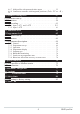
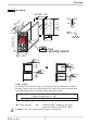
Mounting 1 Mounting 8840 96 (3.78") WEST +0,8 8 max. 60°C min. 0°C max. 95% rel. % 92 11 ) 5" 6 . (4 (0 1 . .0 .1 4. 0 .0 .4 ") 10 .4 (0 ") (3.62" +0.03) min.48 (1.89") 45 +0,6 (1.77" +0.02) RUN Loc security switch -PrgEdit- 48 (1.89") Ü or * Ü * Safety switch: For access to the safety switch, the controller must be withdrawn from the housing. Squeeze the top and bottom of the front bezel between thumb and forefinger and pull the controller firmly from the housing.
Electrical connections 2 Electrical connections 2.1 Connecting diagram 90...
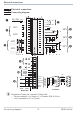
Electrical connections 2.2 Terminal connection Power supply connection 1 See chapter 11 "Technical data" Connection of outputs OUT1/2 2 2 OUT1/2 heating/cooling Relay outputs (250V/2A), potential-free changeover contact Connection of outputs OUT3/4 3 1 2 L a relay (250V/2A), potential-free changeover contact, universal output b current (0/4...20mA) c voltage (0/2...10V) d transmitter supply e logic (0..20mA / 0..
Electrical connections Connection of output U 9 (option) T Supply voltage connection for external energization Connection of outputs OUT5/6 0 (option) Digital outputs (opto-coupler), galvanic isolated, common positive control voltage, output rating: 18...
Electrical connections 3 OUT3 transmitter supply 13V 22mA - 10 + 11 11 12 12 13 14 15 13 + 14 15 - (16) 17 1 3 2 K 10 11 12 13 1 (2) RT = 120...
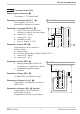
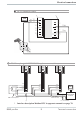
Electrical connections 3 OUT3 as logic output with solid-state relay (series and parallel connection) Series connection Parallel connection SSR _ + Imax=22mA SSR _ + 12 SSR _ 4V SSR _ 10 11 12V + Imax=22mA 4V 12 SSR _ + + 12V Logic 10 11 4V 8840 profilerconnecting example: L1 L2 fuse 1 6700 Limit controller Standard version: N6700Z2100 r other versions on request fuse 8840 profiler 1 2 1 2 3 3 4 5 6 7 8 9 10 11 Logic 12 13 14 15 4 5 6 7 8 9 10 11 12 13 14 fuse contactor S
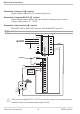
Operation 3 Operation 3.1 Front view 1 8840 WEST 4 5 6 7 8 § $ / ( 2 °C °F RUN 3 9 0 "! % ) & -PrgEdit- LED colours: LED 1, 2, 3, 4: yellow Bargraph: red other LEDs: red g In the upper display line, the process value is always displayed. At parameter, configuration, calibration as well as extended operating level, the bottom display line changes cyclically between parameter name and parameter value. 8840 profiler 11 1 Status of switching outputs OuT.1...
Operation 3.2 Behaviour after power-on After supply voltage switch-on, the unit starts with the operating level. The unit is in the condition which was active before power-off. If the 8840 profiler was in manual mode at supply voltage switch-off, the controller will re-start with the last output value in manual mode at power-on. 3.3 Operating level The content of the extended operating level is determined by means of 8800/8840 Configurator (engineering tool).
Operation 3.4 Error list / Maintenance manager With one or several errors, the extended operating level always starts with the error list. Signalling an actual entry in the error list (alarm, error) is done by the Err LED in the display. To reach the error list press Ù twice.
Operation Name HCA SSr LooP AdA.H AdA.C LiM.1 Lim.2 Lim.3 Inf.1 Inf.2 E.5 dp.1 dp.2 dp.3 dp.4 Description Heating current alarm (HCA) Reason - Heating current circuit interrupted, I< HC.A or I> HC.
Operation g g Saved alarms (Err-LED is lit) can be acknowledged and deleted with the digital input di1/2/3, the è-key or the Ò-key. Configuration, see page 37: ConF / LOGI / Err.r If an alarm is still valid that means the cause of the alarm is not removed so far (Err-LED blinks), then other saved alarms can not be acknowledged and deleted. Self-tuning heating ( ADA.H) and cooling ( ADA.
Operation ti2 td2 t2 - Integral time 2 (cooling) in [s] r only, unless set to OFF - Derivative time 2 (cooling) in [s] r only, unless set to OFF - Minimum cycle time 2 (cooling) in [s] r only, unless Adt0 was set to “no self-tuning” during configuration by means of 8800/8840 Configurator . Parameter set 2: analogous to parameter set 1 (see page 25) 3.5.1 Preparation for self-tuning w Adjust the controller measuring range as control range limits. Set values rnG.L and rnG.
Operation Optimization at the set-point: (see page 18) For optimizing at the set-point, the controller outputs a disturbance variable to the process. This is done by changing the output variable shortly. The process value changed by this pulse is evaluated. The detected process parameters are converted into control parameters and saved in the controller. This procedure optimizes the control loop directly at the set-point. The advantage is in the small control deviation during optimization. 3.5.
Operation Pulse attempt after start-up Condition: - tunE = 1 and sufficient set-point reserve provided. The controller outputs 0% correcting variable or Y.Lo and waits, until the process is at rest (see start conditions page 15) Subsequently, a short pulse of 100% is output (Y=100%) and reset. The controller attempts to determine the optimum control parameters from the process response. If this is completed successfully, these optimized parameters are taken over and used for line-out to the set-point.
Operation Optimization-at-the-set-point procedure: The controller uses its instantaneous parameters for control to the set-point. In lined out condition, the controller makes a pulse attempt. This pulse reduces the correcting variable by max. 20% 1, to generate a slight process value undershoot. The changing process is analyzed and the parameters thus calculated are recorded in the controller. The optimized parameters are used for line-out to the set-point.
Operation Optimization at the set-point for 3-point stepping controller With 3-point stepping controllers, the pulse attempt can be made with or without position feedback. Unless feedback is provided, the controller calculates the motor actuator position internally by varying an integrator with the adjusted actuator travel time. For this reason, precise entry of the actuator travel time (tt), as time between stops is highly important.
Operation 3.5.4 Self-tuning start Start condition: w For process evaluation, a stable condition is required. Therefore, the controller waits until the process has reached a stable condition after self-tuning start. The rest condition is considered being reached, when the process value oscillation is smaller than ± 0,5% of (rnG.H - rnG.L). w For self-tuning start after start-up, a 10% difference from (SP.LO ... SP.Hi) is required.
Operation 3.5.5 Self-tuning cancellation By the operator: Self-tuning can always be cancelled by the operator. For this, press Ù and È key simultaneously.With controller switch-over to manual mode after self-tuning start, self-tuning is cancelled. When self-tuning is cancelled, the controller will continue operating using the old parameter values. By the controller: If the Err LED starts blinking whilst self-tuning is running, successful self-tuning is prevented due to the control conditions.
Operation 3.5.7 Examples for self-tuning attempts (controller inverse, heating or heating/cooling) X Start: heating power switched on W 2 Heating power Y is switched off (1). When the change of process value X was constant during one minute (2), 100% Y the power is switched on (3). 0% At the reversal point, the self-tuning 1 t reversal point Start r 3 attempt is finished and the new parameter are used for controlling to set-point W. X Start: heating power switched off W The controller waits 1,5 minutes (1).
Operation 3.6 Manual self-tuning The optimization aid should be used with units on which the control parameters shall be set without self-tuning. For this, the response of process variable x after a step change of correcting variable y can be used. Frequently, plotting the complete response curve (0 to 100%) is not possible, because the process must be kept within defined limits.
Operation Parameter adjustment effects Parameter Control Pb1 higher increased damping lower reduced damping td1 higher reduced damping lower increased damping ti1 higher increased damping lower reduced damping K = Vmax * Tu Line-out of disturbances Start-up behaviour slower line-out slower reduction of duty cycle faster line-out faster reduction of duty cycle faster response to disturbances faster reduction of duty cycle slower response to disturbances slower reduction of duty cycle slower l
Operation 3.8 Alarm handling Max. three alarms can be configured and assigned to the individual outputs. Generally, outputs OuT.1... OuT.6 can be used each for alarm signalling. If more than one signal is linked to one output the signals are OR linked. Each of the 3 limit values Lim.1 … Lim.3 has 2 trigger points H.x (Max) and L.x (Min), which can be switched off individually (parameter = “OFF”). Switching difference HYS.x and delay dEl.x of each limit value is adjustable.
Operation g The variable to be monitored can be selected seperately for each alarm via configuration The following variables can be monitored: w process value w control deviation xw (process value - set-point) w control deviation xw + suppression after start-up or set-point change After switching on or set-point changing, the alarm output is suppressed, until the process value is within the limits for the first time. At the latest after expiration of time 10 ti1, the alarm is activated.
Operation 3.9 Operating structure After supply voltage switch-on, the controller starts with the operating levels. The controller status is as before power off. 1199 1200 Ù 3 Sek. 1199 para Ù ProG PASS 1199 para PArA Ì Ù PASS 1199 para ConF Ì Ù 1199 CAL Ì PASS Ù 1199 End g PArA - level: g At PArA - level, the right decimal point of the bottom display line is lit continuously. ConF - level: At ConF - level, the right decimal point of bottom display line blinks.
Configuration level 4 Configuration level 4.1 Configuration survey 4.2 g HC.SC P.End FAi.1 FAi.2 FAi.3 O.tYP O.Act Y.1 Y.2 Lim.1 Lim.2 Lim.3 LP.AL HC.AL HC.SC P.End FAi.1 FAi.2 FAi.3 OuT.0 Out.1 O.Src See output 1 S.Lin Corr S.Typ Fnc.2 Y.2 Corr In.F Corr Src.2 Lim.1 In.F Fnc.3 Lim.2 Src.3 Lim.3 HC.AL LP.AL LP.AL HC.AL O.tYP O.Act Y.1 Y.2 Lim.1 Lim.2 Lim.3 LP.AL HC.AL HC.SC P.End FAi.1 FAi.2 FAi.3 OuT.0 Out.1 O.Src See output 1 C.Fnc C.dif mAn C.Act FAIL rnG.L rnG.
Configuration level 4.3 Configuration parameters Cntr Name SP.Fn C.tYP C.Fnc C.dif mAn C.Act FAIL Value range Description Default 1 Basic configuration of setpoint processing 0 set-point controller can be switched over to external set-point (-> LOGI/ SP.E) 1 programmer 8 standard controller with external offset (SP.E) 9 Programmer with external offset (SP.
Configuration level Name rnG.L rnG.H CYCL tunE Strt Adt0 Value range Description Default -1999...9999 X0 (low limit range of control) 1 -100 -1999...9999 X100 (high limit range of control) 1 1200 0 Characteristic for 2-point- and 3-point-controllers 0 standard 3 with constant cycle (see page 48) 0 Auto-tuning at start-up (see page 15 ) 0 At start-up with step attempt, at set-point with impulse attempt 1 At start-up and at set-point with impulse attempt. Setting for fast controlled systems (e.g.
Configuration level Name Value range Description Default 1 Sensor type selection 0 thermocouple type L (-100...900°C) , Fe-CuNi DIN 1 thermocouple type J (-100...1200°C) , Fe-CuNi 2 thermocouple type K (-100...1350°C), NiCr-Ni 3 thermocouple type N (-100...1300°C), Nicrosil-Nisil 4 thermocouple type S (0...1760°C), PtRh-Pt10% 5 thermocouple type R (0...1760°C), PtRh-Pt13% 6 thermocouple type T (-200...400°C), Cu-CuNi 7 thermocouple type C (0...2315°C), W5%Re-W26%Re 8 thermocouple type D (0...
Configuration level InP.2 Name Value range Description I.Fnc Function selection of INP2 0 no function (subsequent input data are skipped) 1 heating current input 2 External set-point SP.E (switch-over -> LOGI/ SP.E) 3 Position feedback Yp 4 Second process value x2 (ratio, min, max, mean) 5 External positioning value Y.E (switch-over r LOGI / Y.E) 6 no controller input (e.g. transmitter input instead) 7 Process value x1 S.tYP Sensor type selection 30 0...20mA / 4...20mA 1 31 0...
Configuration level Name Value range Description Default 30 S.tYP Sensor type selection 0 thermocouple type L (-100...900°C) , Fe-CuNi DIN 1 thermocouple type J (-100...1200°C) , Fe-CuNi 2 thermocouple type K (-100...1350°C), NiCr-Ni 3 thermocouple type N (-100...1300°C), Nicrosil-Nisil 4 thermocouple type S (0...1760°C), PtRh-Pt10% 5 thermocouple type R (0...1760°C), PtRh-Pt13% 6 thermocouple type T (-200...400°C), Cu-CuNi 7 thermocouple type C (0...2315°C), W5%Re-W26%Re 8 thermocouple type D (0...
Configuration level Lim Name Value range Description Default 1 Function of limit 1 0 switched off 1 measured value monitoring 2 Measured value monitoring + alarm status storage. A stored limit value can be reset via error list, è-key, Ò-key or a digital input ( -> LOGI/ Err.r) 3 signal change (change/minute) 4 signal change and storage (change/minute) 1 Src.
Configuration level Name Value range Description Default 0 Source of limit 2 0 process value 1 control deviation xw (process value - set-point) 2 control deviation xw (with suppression after start-up and set-point change) After switch-on or set-point changing, the alarm output is suppressed, until the process value is within the limits for the first time.
Configuration level Name Value range Description Default 0 Alarm heat current function (INP2) 0 switched off 1 Overload short circuit monitoring 2 Break and short circuit monitoring 0 LP.AL Monitoring of control loop interruption for heating 0 switched off / inactive 1 active. If ti1=0 LOOP alarm is inactive! OFF...999999 OFF Operating hours (only visible with 8800/8840 Configurator!) Hour OFF Swit OFF...999999 Output switching cycles (only visible with 8800/8840 Configurator!) HC.AL Out.1 Name O.Act Y.
Configuration level Name FAi.2 FAi.3 Prg.1 Prg.2 Prg.3 Prg.
Configuration level Name Y.2 Lim.1 Lim.2 Lim.3 LP.AL HC.AL HC.SC P.EnD FAi.1 FAi.2 FAi.3 Prg.1 Prg.2 Prg.3 Prg.4 8840 profiler Value range Description Default 0 Controller output Y2 (only visible when O.TYP=0) 0 not active 1 active 1 Limit 1 signal (only visible when O.TYP=0) 0 not active 1 active 0 Limit 2 signal (only visible when O.TYP=0) 0 not active 1 active 0 Limit 3 signal (only visible when O.TYP=0) 0 not active 1 active 0 Interruption alarm signal (LOOP) (only visible when O.
Configuration level Name CAll Out.0 Out.1 O.Src fOut Value range Description Default 0 Operator call 0 not active 1 active -1999...9999 Scaling of the analog output for 0% (0/4mA or 0/2V, only 0 visible when O.TYP=1..5) -1999...9999 Scaling of the analog output for 100% (20mA or 10V, only 100 visible when O.TYP=1..5) 1 Signal source of the analog output OUT3 (only visible when O.TYP=1..
Configuration level Name Value range Description SP.2 Switching to second setpoint SP.2 0 no function (switch-over via interface is possible) 2 DI1 switches 3 DI2 switches (only visible with OPTION) 4 DI3 switches (only visible with OPTION) 5 è - key switches SP.E Switching to external setpoint SP.
Configuration level Name m.Loc Err.r Pid.2 P.run P.off I.Chg di.
Configuration level Name fDI3 Value range Description Forcing di3 (only visible with 8800/8840 Configurator!) 0 No forcing 1 Forcing via serial interface Default Value range Description Baudrate of the interface (only visible with OPTION) 0 2400 Baud 1 4800 Baud 2 9600 Baud 3 19200 Baud 1...247 Address on the interace (only visible with OPTION) Data parity on the interface (only visible with OPTION) 0 no parity (2 stop bits) 1 even parity 2 odd parity 3 no parity (1 stopbit) 0...
Configuration level Name FrEq ICof IAda IExo ILat PTmp pPre pRun pSwi pCom Pass IPar ICnf ICal Value range Description Switching 50 Hz / 60 Hz (only visible with 8800/8840 Configurator!) 0 50 Hz 1 60 Hz Block controller off (only visible with 8800/8840 Configurator!) 0 Released 1 Blocked Block auto tuning (only visible with 8800/8840 Configurator!) 0 Released 1 Blocked Block extended operating level (only visible with 8800/8840 Configurator!) 0 Released 1 Blocked Suppression error storage 0 Released
Configuration level Name CDis3 TDis3 PDis3 T.dis3 T.InF1 T.InF2 t.PrG01 t.PrG02 w w w t.PrG16 8840 profiler Value range Description Display 3 controller operating level (only visible with 8800/8840 Configurator!) 0 No value / only text 1 Display of value 2 Output value as bargraph 3 Control deviation as bargraph 4 Process value as bargraph 2...60 Display 3 display alternation time [s] (only visible with 8800/8840 Configurator!) display 3 programmer-operating level 0 Segm.-No., Segm.-Type, Progr.
Configuration level Lin Name Lin In.1 Ou.1 In.2 Ou.2 : : (only visible with 8800/8840 Configurator Value range Description Linearization for inputs INP1 or INP3 Access to this table is always with selection special thermocouple for InP.1 or InP.3or with setting S.Lin = 1: special linearization for linearization. Default: KTY 11-6 (0...4,5 kOhm) -999.0..99999 Input value 1 The signal is in [µV] or in [[] dependent of input type 0,001...9999 Output value 1 Signal assigned to In.1 -999.0..
Configuration level 4.4 Set-point processing The set-point processing structure is shown in the following picture: 8840 WEST Xeff Internal set-point °C °F RUN Ü -PrgEdit- Limiting Programmer 0 8 + external SP.E set-point Ü + * Ramp 1 9 SP.Lo Ö Effective r.SP set-point - LED 2nd SP.2 set-point Index: Ü : int/ext-setpoint switching * : configuration SP.Fn Ö : SP / SP.2 switching SP.
Configuration level 4.5 8840 profiler cooling functions With the 8840 profiler , configuration parameter CYCL (ConF/ Cntr/ CYCL) can be used for matching the cycle time of 2-point and 3-point controllers. This can be done using the following 4 methods. 4.5.1 Standard ( CyCl= 0 ) The adjusted cycle times t1 and t2 are valid for 50% or -50% correcting variable. With very small or very high values, the effective cycle time is extended to prevent unreasonably short on and off pulses.
Configuration level 4.6 Configuration examples 4.6.1 On-Off controller / Signaller (inverse) InL.1 SP.LO SP SP.Hi InH.1 InP.1Ê 100% HYS.L Out.1Â HYS.H 0% ConF/Cntr: SP.Fn = 0 C.Fnc = 0 C.Act = 0 ConF/Out.1: O.Act Y.1 PArA/Cntr: Hysl PArA/Cntr: HysH PArA/SEtP: SP.LO SP.Hi g set-point controller signaller with one output inverse action (e.g. Heating applications) =0 action Out.1 direct =1 control output Y1 active = 0...9999 switching difference (below set-point) = 0...
Configuration level 4.6.2 2-point controller (inverse) InL.1 SP.LO InP.1Ê SP SP.Hi InH.1 PB1 100% Out.1Â 0% ConF / Cntr: SP.Fn C.Fnc C.Act ConF / Out.1: O.Act Y.1 Pb1 PArA / Cntr: PArA / SEtP: g ti1 td1 t1 SP.LO SP.Hi = 0 = 1 = 0 set-point controller 2-point controller (PID) inverse action (e.g. heating applications) = 0 action Out.1 direct = 1 control output Y1 active = 1...9999 proportional band 1 (heating) in units of phys. quantity (e.g. °C) = 0,1...
Configuration level 4.6.3 3-point controller (relay & relay) InL.1 SP.LO InP.1Ê SP PB2 PB1 100% Out.1Â 0% ConF / Cntr: SP.Fn C.Fnc C.Act ConF / Out.1: O.Act Y.1 Y.2 O.Act Y.1 Y.2 Pb1 PArA / Cntr: Pb2 PArA / SEtP: 8840 profiler 100% Out.2Â 0% ConF / Out.2: SP.Hi InH.1 ti1 ti2 td1 td2 t1 t2 SH SP.LO SP.Hi = 0 = 3 = 0 set-point controller 3-point controller (2xPID) action inverse (e.g. heating applications) = 0 action Out.
Configuration level 4.6.4 3-point stepping controller (relay & relay) InL.1 SP.LO InP.1Ê SP PB1 100% Out.1Â SP.Hi InH.1 SH 0% SP.Fn C.Fnc C.Act = 0 = 4 = 0 ConF / Out.1: O.Act Y.1 Y.2 O.Act Y.1 Y.2 Pb1 = = = = = = = ti1 td1 t1 SH tP tt SP.LO SP.Hi = = = = = = = = PArA / Cntr: PArA / SEtP: g Out.2Â 0% ConF / Cntr: ConF / Out.2: 100% set-point controller 3-point stepping controller inverse action (e.g. heating applications) 0 action Out.
Configuration level 4.6.5 Continuous controller (inverse) SP.LO InL.1 InP.1Ê SP SP.Hi InH.1 PB1 20 mA Out.3Â 0/4 mA ConF / Cntr: SP.Fn C.Fnc C.Act = 0 = 1 = 0 ConF / Out.3: O.tYP Out.0 Out.1 Pb1 = = = = 1/2 -1999...9999 -1999...9999 1...9999 ti1 td1 t1 SP.LO SP.Hi = = = = = 0,1...9999 0,1...9999 0,4...9999 -1999...9999 -1999...9999 PArA / Cntr: PArA / SEtP: g g set-point controller continuous controller (PID) inverse action (e.g. heating applications) Out.
Configuration level 4.6.6 ∆ - Y - Off controller / 2-point controller with pre-contact InL.1 SP.LO SP InP.1Ê SP.Hi InH.1 PB1 100% Out.1Â 0% Out.2Â SH ConF / Cntr: SP.Fn C.Fnc C.Act ConF / Out.1: O.Act Y.1 Y.2 O.Act Y.1 Y.2 Pb1 ConF / Out.2: PArA / Cntr: ti1 td1 t1 SH d.SP PArA / SEtP: Configuration examples SP.LO SP.Hi d.SP = 0 = 2 = 0 set-point controller ∆ -Y-Off controller inverse action (e.g. heating applications) = 0 action Out.
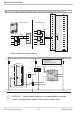
Configuration level 4.6.7 8840 profiler with measured value output phys. quantity Out.1 mA / V phys. quantity Out.0 20mA 10V 0/4mA 0/2V 90...250VAC 24VUC } NL 1 2 1 2 3 3 4 5 6 7 8 9 OUT3 OUT4 10 11 12 U 13 14 15 4 5 6 7 8 9 10 11 12 13 14 U 15 (16) INP1 17 + ConF / Out.3 / 4: O.tYP = = = = Out.0 = 1 2 3 4 -1999...9999 Out.1 = -1999...9999 O.Src = 3 8840 profiler 55 Out.3/ 4 0...20mA continuous Out.3/ 4 4...20mA continuous Out.3/ 4 0...10V continuous Out.3/ 4 2...
Configuration level 4.6.8 Continuous controller with integrated positioner ( Cntr/ C.Fnc = 6 ) SP W INP.1 X Ycontinuous Ypid OUT.4 Master controller W Y.1 INP.2 X OUT.1 M Y.2 OUT.2 Position controller This is basically a cascade. A tracking controller with three-point stepping behaviour which operates with Yp as process value (INP.2 / INP.3) is used with the continuous controller. ConF / Cntr SP.Fn C.Fnc = 0 = 6 C.Act = 0 ConF / InP.2: I.Fnc S.typ = 3 = 50 Position featback Yp Sensor e.
Parameter setting level 5 Parameter setting level 5.1 Parameter survey g Inl.2 OuL.2 InH.2 OuH.2 tF.2 InL.3 OuL.3 InH.3 OuH.3 tF.3 E.tc End InL.1 OuL.1 InH.1 OuH.1 tF.1 Lim Limit value functions Input 3 Input 2 InP.3 SP.Lo SP.Hi SP.2 r.SP Input 1 SEtP Set-point and process value PAr.2 Pb12 Pb22 ti12 ti22 td12 td22 InP.2 Pb1 Pb2 ti1 ti2 td1 td2 t1 t2 SH Hys.l Hys.H d.SP tP tt Y.Lo Y.Hi Y2 Y0 Ym.H L.Ym oFFS tEmp InP.1 Ì 2.
Parameter setting level 5.2 Parameters Cntr Name Value range Description Default 1...9999 1 Proportional band 1 (heating) in phys. dimensions (e.g. °C) 100 Pb1 1...9999 1 Proportional band 2 (cooling) in phys. dimensions (e.g. °C) 100 Pb2 0,1...9999 Integral action time 1 (heating) [s] 180 ti1 0,1...9999 Integral action time 2 (cooling) [s] 180 ti2 0,1...9999 Derivative action time 1 (heating) [s] 180 td1 0,1...9999 Derivative action time 2 (cooling) [s] 180 td2 0,4...
Parameter setting level Name Value range Description 0,1...9999 Integral action time 1 (heating) [s], 2. parameter set Ti12 0,1...9999 Derivative action time 1 (heating) [s], 2. parameter set Td12 0,1...9999 Derivative action time 2 (cooling) [s], 2. parameter set Td22 Default 180 180 180 SEtP Name Value range Description SP.LO -1999...9999 Set-point limit low for Weff SP.Hi -1999...9999 Set-point limit high for Weff -1999...9999 Set-point 2. SP.2 0...9999 r.SP Set-point gradient [/min] -1999...
Parameter setting level Name Value range Description OuH.3 -1999...9999 Displayed value for the upper scaling point 0,0...999,9 Filter time constant [s] t.F3 0...100 (°C) External cold-junction reference temperature (external TC) Etc.3 32...212 (°F Default 20 0,5 OFF Lim Name L.1 H.1 HYS.1 dEl.1 L.2 H.2 HYS.2 dEl.2 L.3 H.3 HYS.3 dEl.3 HC.A g Value range Description -1999...9999 Lower limit 1 -1999...9999 Upper limit 1 0...9999 Hysteresis limit 1 0...9999 Alarm delay from limit value 1 -1999...
Parameter setting level 5.3 Input scaling When using current, voltage or resistance signals as input variables for InP.1, InP.2 or/and InP.3 scaling of input and display values at parameter setting level is required. Specification of the input value for lower and higher scaling point is in the relevant electrical unit (mA / V / Ω). phys. quantity OuH.x phys. quantity mA / V OuL.x InH.x mA/V InL.x S.tYP 30 (0...20mA) 40 (0...10V) Input signal 0 … 20 mA 4 … 20 mA 0 … 10 V 2 … 10 V InL.
Calibration level 6 Calibration level Measured value correction ( CAL) is only visible if ConF / InP.1 / Corr = 1 or 2 is chosen. The measured value can be matched in the calibration menu ( CAL). Two methods are available: Offset correction ( ConF/ InP.1 / Corr =1 ): display standard setting offset correction w possible on-line at the process OuL.1new OuL.1old InL.1 X 2-point correction ( ConF/ InP.
Calibration level Offset correction ( ConF/ InP.1 / Corr =1 ): r 1199 °C °F para func Ada Err 1200 SP.E SP.2 r Ù r PArA 3 sec. Ì : CAL r Ù r InP.1 r Ù r InL.1 r Ù r OuL.1 È r Ù Ì r End r Ù InL.1: The input value of the scaling point is displayed. The operator must wait, until the process is at rest. Subsequently, the operator acknowledges the input value by pressing key Ù. OuL.1: The display value of the scaling point is displayed. Before calibration, OuL.1 is equal to InL.1.
Calibration level 2-point correction ( ConF/ InP.1 / Corr = 2): 1199 °C °F 1200 r Ù r 3 sec. SP.E SP.2 PArA Ì r para func Ada Err ConF r Ì CAL r Ùr InP.1 r Ù r InL.1 r Ù InL1 InP.2 OuL.1 È Ì InP.3 È Ì Ù End g È È Ì Ù È rÙ Ì InH.1 r Ù È InH.1 Ù OuH.1 È rÙ Ì InL.1: The input value of the lower scaling point is displayed. The operator must adjust the lower input value by means of a process value simulator and confirm the input value by pressing key Ù. OuL.
Programmer level 7 Programmer level 7.1 Parameter survey ÈÌ prg b.lo b.hi d.00 type sp pt d.out End Copy Program copying Programmer level Edit Programmer editing Prog src dst ··· type sp pt tout g Setting: w The parameters can be set by means of keys ID w Transition to the next parameter is by pressing key Ù . w After the last parameter of a group, donE is displayed and an automatic transition the next group occurs Return to the start of a group is by pressing key Ù during 3 sec.
Programmer level 7.2 Parameters ProG Name b.Lo b.Hi d.00 tYPE SP Pt d.Out tYPE SP Pt d.Out tYPE SP Pt d.Out tYPE SP Pt d.Out Parameters Value Range Description 0...9999 Bandwidth lower limit 0...9999 Bandwidth upper limit Resetvalue of control track 1 ... 4 0 1 2 3 4 5 6 7 8 9 10 11 12 13 14 15 0 1 2 3 4 5 6 7 8 -1999...9999 0...
Programmer level Name tYPE SP Pt d.Out tYPE SP Pt d.Out tYPE SP Pt d.Out tYPE SP Pt d.Out w w w tYPE Pt d.Out tYPE SP Pt d.Out 8840 profiler Value Range Description segment type 3 (see segment type 1) -1999...9999 segment end set-point 5 0...9999 segment time/-gradient 5 control track 1...4 - 5 (see parameter d.00) segment type 6 (see segment type 1) -1999...9999 segment end set-point 6 0...9999 segment time/-gradient 6 control track 1...4 - 6 (see parameter d.
Programmer level 7.3 Programmer description 7.3.
Programmer level 7.3.2 Programmer set-up: The instrument is factory-configured as a program controller. The following settings must be checked: g w Set-point function For using the controller as a programmer, select parameter SP.Fn = 1 / 9 in the ConF menu (r page 23). w Time base The time base can be set to hours:minutes or minutes:seconds in the ConF menu; parameter t.bAS (r page 24).
Programmer level Programmer parameter setting 8(16) programmers with 16 segments each are available to the user. The relevant parameters must be determined in menu ProG . (r page 57). The procedure for editing a program is shown below. 1199 1200 Ù 3 Sek. 1199 Ù ProG para 1199 para Edit Program Ù para 1199 Ì Prg Ù Ì Prog. 01 Select the program you want to edit by means of keys ID and confirm it with Ù. Start by setting the bandwidth high and low (b.Lo; b.
Programmer level 7.3.3 Operation Programmer operation (run/stop, preset und reset) is via front panel, digital inputs or interface (8800/8840 Configurator, superordinate visualization, ...). Front panel operation For programmer operation via the front panel keys, the digital input function (di.Fn r page 36) must be set to key operation. or Function key è can be used for switch-over to programmer controller . If programmer was selected, the func LED is lit.
Programmer level 7.3.4 Programmer display para func Ada Err 01 OFF para func Ada Err 01/12:30 para func Ada Err 16 End para func Ada Err ûûû_____ SP.E SP.2 SP.E SP.2 SP.E SP.2 SP.E SP.2 run run run run Programmer description Programmer is in reset and the internal controller set-point is effective. Segment or program number and OFF are displayed (configurable with 8800/8840 Configurator: Configuration r Other r PDis3). Programmer running (run LED is lit).
Programmer level 7.3.5 Segment type Rampsegment (time) Sp With a ramp segment (time), the set-point runs linearly from the start value (end of previous segment) towards the target set-point (Sp) of the relevant segment during time Pt (segment duration). Pt Rampsegment (gradient) Sp Pt Hold segment Step segment Pt With a hold segment, the end set-point of the previous segment is output constantly during a defined time which is determined by parameter Pt.
Programmer level 7.3.6 Bandwidth monitoring Sp, X set-point profile Bandwidth monitoring is valid for all program segments. An individual bandwidth can be determined for each program. When leaving the bandwidth (b.Lo = low limit; b.Hi = high limit), the programmer is stopped (run LED Stop Stop flashes). The program continues running when the process value is within the predefined bandwidth again. g g b.Hi b.
Special functions 8 Special functions 8.1 8840 profiler as Modbus master Additions othr Name (only visible with 8800/8840 Configurator!) Value range Description Default 0 Controller is used as Modbus master 0 Slave 1 Master 0...200 60 Cycle time [ms] for the Modbus master to transmit its data to the bus. 1...65535 1 Target address to which the with AdrU specified data is given out on the bus. 1...65535 1 Modbus address of the data that Modbus master gives to the bus. 0...
Special functions 8.2 Linearization Linearization for inputs INP1 or INP3 Access to table “ Lin” is always with selection of sensor type S.TYP = 18: special thermocouple in INP1 or INP3, or with selection of linearization S.Lin 1: special linearization. Dependent of input type, the input signals are specified in µV or in Ohm dependent of input type. With up to 16 segment points, non-linear signals can be simulated or linearized. Every segment point comprises an input (In.1 … In.16) and an output (Ou.
8800/8840 Configurator 9 8800/8840 Configurator 8800/8840 Configurator is the projection environment for the corresponding West controllers.
Versions 10 Versions 8 8 4 0 1 00 Flat-pin connectors 0 Screw terminals 1 90..250V AC, 4 relays 0 24VAC / 18..30VDC, 4 relays 1 90..250V AC, 3 relays + mA/logic 2 24VAC / 18..30VDC, 3 relays +mA/logic 3 90..250V AC, 2 relays + 2xmA/logic 4 24VAC / 18..
Technical data 11 Technical data Linearization: INPUTS Decimal point: Input circuit monitor: PROCESS VALUE INPUT INP1 Resolution: Decimal point: Dig. input filter: Scanning cycle: Measured value correction: > 14 bits 0 to 3 digits behind the decimal point adjustable 0,000...
Technical data CONTROL INPUTS DI2, DI3 (OPTION) The digital input di2 located on the A-card and di2 located on the option card are or-linked. Configurable as switch or push-button! Optocoupler input for active triggering. Nominal voltage Current sink (IEC 1131 type 1) Logic “0” Logic “1” Current requirement 24 V DC external -3...5 V 15...30 V approx.. 5 mA Operating life (electr.): 600.000 duty cycles with max.
Technical data POWER SUPPLY Permissible temperatures Dependent of order: AC SUPPLY Voltage: Frequency: Power consumption 90...260 V AC 48...62 Hz approx. 7,0 VA For specified accuracy: Warm-up time: For operation: For storage: 0...60°C ≥ 15 minutes -20...65°C -40...70°C UNIVERSAL SUPPLY 24 V UC Humidity AC voltage: Frequency: DC voltage: Power consumption: 75% yearly average, no condensation 20,4...26,4 V AC 48...62 Hz 18...31 V DC approx..
Technical data Certifications UL-approval Electrical connections w flat-pin terminals 1 x 6,3mm or 2 x 2,8mm to DIN 46 244 or w screw terminals for 0,5 to 2,5mm² Mounting Panel mounting with two fixing clamps at top/bottom or right/left, High-density mounting possible Mounting position: uncritical Weight: 0,27kg Accessories delivered with the unit Operating manual Fixing clamps 82 8840 profiler
Technical data Table 1 Thermocouples measuring ranges Thermoelementtype L Fe-CuNi (DIN) J Fe-CuNi K NiCr-Ni N Nicrosil/Nisil S PtRh-Pt 10% R PtRh-Pt 13% T Cu-CuNi C W5%Re-W26%Re D W3%Re-W25%Re E NiCr-CuNi B * PtRh-Pt6% Measuring range -100...900°C -100...1200°C -100...1350°C -100...1300°C 0...1760°C 0...1760°C -200...400°C 0...2315°C 0...2315°C -100...1000°C 0(100)...1820°C -148...1652°F -148...2192°F -148...2462°F -148...2372°F 32...3200°F 32...3200°F -328...752°F 32...4199°F 32...4199°F -148...
Safety hints 12 Safety hints This unit was built and tested in compliance with VDE 0411-1 / EN 61010-1 and was delivered in safe condition. The unit complies with European guideline 89/336/EWG (EMC) and is provided with CE marking. The unit was tested before delivery and has passed the tests required by the test schedule. To maintain this condition and to ensure safe operation, the user must follow the hints and warnings given in this operating manual.
Safety hints MAINTENANCE, REPAIR AND MODIFICATION The units do not need particular maintenance. Warning a When opening the units, or when removing covers or components, live parts and terminals may be exposed. Before starting this work, the unit must be disconnected completely. l After completing this work, re-shut the unit and re-fit all covers and components. Check if specifications on the type label must be changed and correct them, if necessary.
Index 0-9 2-point correction. . . . . . . . . . . . 62 E Environmental conditions . . . . . . . 81 Equipment . . . . . . . . . . . . . . . 78 Error list . . . . . . . . . . . . . . . . 13 A Alarm handling . . . . . . . . . . 26 - 27 F Front view . . . . . . . . . . . . . . . 11 B Bargraph . . . . . . . . . . . . . . . . 11 BlueControl. . . . . . . . . . . . . . . 77 Bus interface Technical Data. . . . . . . . . . 81 I Input INP1 Configuration . Parameters . . . Technical data .
Technical data . Output OUT2 Configuration . Technical data . Output OUT3 Configuration . Technical data . Output OUT4 Configuration . Technical data . Output OUT5 Configuration . Technical data . Output OUT6 Configuration . Technical data . . . . . . . . . . 80 . . . . . . . . . 38 . . . . . . . . . 80 . . . . . . . . . 38 . . . . . . . . . 80 . . . . . . . . . 40 . . . . . . . . . 80 . . . . . . . . . 40 . . . . . . . . . 80 . . . . . . . . . 40 . . . . . . . . .
Notes 13 Notes 88 8840 profiler
Notes 8840 profiler 89
Subject to alterations without notice West Instruments The Hyde Business Park Brighton BN2 4JU UK Printed in Germany 9499-040-70711 (09/2003) A6