
User Manual

Alphabetic Index - Volume 1
A
Alarm 1 Value
Band Alarm 2-3
Deviation Alarm 2-3
Process High Alarm 2-3
Process Low Alarm 2-3
Alarm 2 Value
Band alarm 2-3
Deviation alarm 2-3
Process High alarm 2-3
Process Low alarm 2-3
Alarm Operation
Illustration of2-9
Alarm Status
Display of 1-3
Displaying (Set Up mode)2-4
Auto Pre-Tune Enable/Disable 2-12
B
Band Alarm 1 2-8
Band Alarm 2 2-10
Bias (Manual Reset) 2-7
C
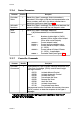
Communications Line Release Time
Maximum Value 3-1
Communications Message
Format 3-2
D
Deadband 2-5
Decimal Point Position
Input scale range 2-4
Derivative Time Constant (Rate) 2-5
Deviation Alarm 1 2-10
Deviation Alarm 2 2-10
Digital Filter Time Constant 2-3
H
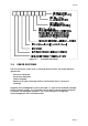
Hardware Definition Code
Explanation of 1-7
Viewing 1-7
I
Input Filter Time Constant 2-2
Input Over-Range
Indication of 1-4
Input Scale Range
Decimal point position 2-4
Input Scale Range Maximum 2-4
Input Scale Range Minimum 2-4
Input Under-Range
Indication of 1-4
Integral Time Constant (Reset) 2-5
L
Lock Value 2-12
Loop Alarm 2-10
Loop Alarm Enable 2-10
Loop Alarm Time 2-11
M
Manual Control Mode
De-selection of 1-4
Indication of 1-4
Selection of 1-4
Manual Control Selection
Enable/Disable 2-12
Manual Reset (Bias) 2-7
Manual Tuning
Controllers with Output 1 and
Output 2 2-14
Controllers with
Output 1 only 2-13
O056-IDX 1
59125