
User Manual
2.2.3 Output Power 1
This parameter is the current Output 1 power level. It is a “Read Only” parameter
and is not adjustable.
2.2.4 Output Power 2
This parameter is the current Output 2 power level (if Output 2 is fitted). It is a
“Read Only” parameter and is not adjustable. If Output 2 is not fitted, this
parameter display is not applicable.
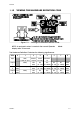
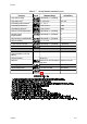
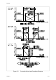
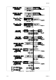
2.2.5 Proportional Band 1
This parameter is the portion of the input span of the Controller over which the
Output 1 power level is proportional to the displayed process variable value. The
function of the Proportional Band 1 is illustrated in Figure 2 -2 .
2.2.6 Proportional Band 2
This parameter is the portion of the input span of the Controller over which the
Output 2 power level is proportional to the displayed process variable value. In
Figure 2-2, Proportional Band 2 is shown (a) with a non-zero value (Case 1 and
Case 2) - PID control, and (b) with a zero value (Case 3) - ON/OFF control.
2.2.7 Reset ( Integral Time Constant)
This parameter is not applicable if Proportional Band 1 (see Subsection 2.2.5 ) is set
to 0 (ON/OFF control).
2.2.8 Rate ( Derivative Time Constant)
This parameter is not applicable if Proportional Band 1 (see Subsection 2.2.5 ) is set
to 0 (ON/OFF control).
2.2.9 O verlap/Deadband
This defines the portion of the Proportional Band (Proportional Band 1 +
Proportional Band 2) over which both outputs are active (or, in the case of a
deadband, neither output is active). The function of the overlap/deadband is
illustrated in Figure 2 - 2 . This parameter is not applicable if Proportional Band 1 = 0
or if Output 2 is not fitted. Note that, with Output 2 set to ON/OFF control (Figure 2-2
Case 3), the Overlap/Deadband parameter has the effect of moving the ON
Differential band of Output 2 to create an overlap (positive values) or a
deadband (negative values). When Overlap/Deadband = 0, the “Output 2 OFF”
edge of the Output 2 ON/OFF Differential band coincides with the point at which
Output 1 reaches 0%.
2-5 O054-2
59125