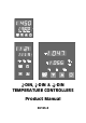
-DIN, 81 -DIN & 16 -DIN TEMPERATURE CONTROLLERS 1 4 Product Manual 59125-3
PREFACE This manual comprises two volumes: Volume 1: This supports normal operation of the 41-DIN, 18-DIN and 161 -DIN Temperature Controllers. In normal operation, all actions taken by the user are to be in front of the panel. Volume 2: This supports the installation, commissioning and configuring of the 41-DIN, 18-DIN and 161 -DIN Temperature Controllers. It is intended for use only by personnel who are trained, equipped and authorised to carry out these functions.
59125 1 4 1 -DIN, 18 -DIN & 16 -DIN TEMPERATURE CONTROLLERS PRODUCT MANUAL VOLUME 1 OPERATING INSTRUCTIONS In normal operation, the operator must not remove the Controller from its housing or have unrestricted access to the rear terminals, as this would provide potential contact with hazardous live parts. Installation and configuration must be undertaken by technically-competent servicing personnel. This is covered in Volume 2 of this manual. Contents - Volume 1 1 OPERATOR MODE 1-1 1.
59125 2 SET UP MODE 2-1 2.1 ENTRY INTO SET UP MODE 2-1 2.2 SET UP MODE PARAMETERS 2-2 2.3 OPERATOR MODE DISPLAYS 2-13 2.4 TUNING THE CONTROLLER MANUALLY 2-13 2.5 SELF-TUNE AND PRE-TUNE FACILITIES 2-14 2.6 EXIT FROM SET UP MODE 2-15 3 RS485 SERIAL COMMUNICATIONS 3-1 3.1 COMMUNICATIONS ENABLE/DISABLE 3-1 3.2 PHYSICAL REQUIREMENTS 3-1 3.3 INDIVIDUAL PARAMETERS 3-5 3.
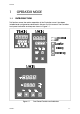
9125 1 1.1 OPERATOR MODE INTRODUCTION This Section covers the routine operation of the Controller, once it has been installed and configured as described in Volume 2 of this manual. The Controller front panel indicators and keys are shown in Figure 1-1.
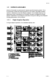
59125 1.2 DISPLAYS AVAILABLE After the Controller has performed its power-up self-test (during which, if the Function key is held down during power-up, the current Controller firmware revision is displayed), the initial displays appear. The available displays are dependent upon (a) whether the Controller has been configured for Single Setpoint operation or Dual Setpoint operation and (b) the setting of the Setpoint Strategy parameter in Set Up Mode. 1.2.
59125 1.2.2 Dual Setpoint Operation In dual setpoint operation, the available displays are: 1.3 ADJUSTING THE SETPOINT/SETPOINT RAMP RATE The setpoint/setpoint ramp rate (whichever is selected - see previously) may be adjusted using the Raise/Lower keys. The ramp rate may be adkusted in the range 1 to 9999. Any attempt to increase the ramp rate value beyond 9999 will cause the upper display to go blank and setpoint ramping to be switched OFF.
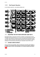
59125 Figure 1-2 1.5 Alarm Status Display OVER-RANGE/UNDER-RANGE DISPLAYS The upper display will indicate if the process variable is higher than the input scale maximum limit (over-range), or lower than the input scale minimum limit (under-range) as shown on the right. 1.6 SENSOR BREAK INDICATION If a break is detected in the sensor circuit, the upper display shows: The reaction of the outputs and alarms to a detected sensor break is dependent upon the input type and is defined in Appendix A. 1.
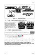
59125 1.8 PRE-TUNE FACILITY This facility may be used to set the Controller’s PID parameters to values which are approximately correct, in order to provide a base from which the Self-Tune facility may subsequently optimise tuning. Pre-Tune may be engaged (and subsequently dis-engaged) as follows: NOTE: The Pre-Tune facility will not engage if (a) the setpoint is currently ramping, (b) the process variable is within 5% of input span of the setpoint, or (c) an erroneous key sequence is used.
59125 Since Pre-Tune is a single-shot operation, it will automatically dis-engage itself once the operation is complete. 1.9 SELF-TUNE FACILITY This facility is be used to optimise tuning whilst the Controller is operating.
59125 1.10 VIEWING THE HARDWARE DEFINITION CODE Figure 1-3 Viewing the Hardware Definition Code NOTE: An automatic return is made to the normal Operator display after 30 seconds.
59125 2 2.1 SET UP MODE ENTRY INTO SET UP MODE See Figure 2-1.
59125 NOTE: If, on entry into Set Up Mode, the upper display initially shows all decimal point positions illuminated), this indicates that one or more of the critical configuration parameters - typically input range or output use/type - have been altered in value/setting and, as a consequence, all Set Up Mode parameters have been automatically set to their default values/settings. To clear this display, simply alter the value/setting of any Set Up Mode parameter (see below). 2.
59125 Table 2-1 Parameter Legend Set Up Mode Parameters Adjustment Range Default Value Digital Filter Time Constant OFF, 0.5 to 100.0 secs. In 0.5 sec. increments 2.0 seconds Process Variable Offset ±Span of Controller 0 Output Power 0 to 100% Read only 0 to 100% Read only 0.0 (ON/OFF control) to 999.9% of input span 10.0% 0.0 (ON/OFF control) to 999.9% of input span 10.
59125 Table 2-1 Parameter Legend Loop Alarm Enable Set Up Mode Parameters (cont.
59125 2.2.3 Output Power 1 This parameter is the current Output 1 power level. It is a “Read Only” parameter and is not adjustable. 2.2.4 Output Power 2 This parameter is the current Output 2 power level (if Output 2 is fitted). It is a “Read Only” parameter and is not adjustable. If Output 2 is not fitted, this parameter display is not applicable. 2.2.
59125 Figure 2-2 O054-2 Proportional Band and Deadband/Overlap 2-6
59125 2.2.10 Bias (Manual Reset) This bias to the output power is expressed as a percentage of output power. This parameter is not applicable if Proportional Band 1 = 0. 2.2.11 ON/OFF Differential This is a switching differential used when one or both outputs have been set to ON/OFF control (i.e. Proportional Band 1 or Proportional Band 2 or both = 0). 2.2.12 Setpoint High Limit This is the maximum limit for setpoint adjustment.
59125 2.2.16 Output 1 Power Limit This parameter is used to limit the power level of Output 1 and may be used to protect the process being controlled. If no protection is required, this parameter may be set to 100%. IThis parameter is not applicable if Proportional Band 1 is set to 0. 2.2.17 Output 1 Cycle Time The cycle time value required is dependent upon the process being controlled and the type of output being used for Output 1.
59125 Figure 2-3 2-9 Alarm Operation O054-2
59125 2.2.22 Deviation (High/Low) Alarm 1 Value This parameter, applicable only if Alarm 1 is selected to be a Deviation High/Low Alarm, defines a value above (positive value - Deviation High alarm) or below (negative value - Deviation Low alarm) the setpoint; if the process variable deviates from the setpoint by a margin greater than that defined by this parameter, Alarm 1 goes active. The operation of Deviation Alarms is illustrated in Figure 2-3. 2.2.
59125 if the saturated output has not caused the process variable to be corrected by a pre-determined amount V after a time T has elapsed, the Loop Alarm goes active. Subsequently, the Loop Alarm facility repeatedly checks the process variable and the control output(s). When the process variable starts to change value in the correct sense or when the saturated output comes out of saturation, the Loop Alarm is de-activated.
59125 2.2.30 Scale Range Maximum This parameter, applicable only if a linear input is fitted, defines the scaled input value when the process variable input hardware is at its maximum value. This parameter can be set to a value less than (but not equal to) Scale Range Minimum, in which case the sense of the input is reversed. Decimal point position is defined by the Scale Range Decimal Point parameter (see Subsection 2.2.29). 2.2.
59125 2.3 OPERATOR MODE DISPLAYS Once the complete cycle of Set Up Mode parameters has been displayed, the user may then step through the Operator Mode displays (see Subsection 1.2), making adjustments where required, before re-starting the Set Up Mode parameter cycle, as shown in Table 2-1. 2.4 2.4.
59125 Figure 2-4 2.4.2 Manual Tuning Parameters - Output 1 only Controllers Fitted with Output 1 and Output 2 Before starting to tune the Controller to the load, check that the Setpoint High and Low Limits (SPhi and SPLo) are set to safe levels - see Subsections 2.2.12 and 2.2.13. The following simple technique may be used to determine values for proportional band (Pb1), derivative time constant (rAtE) and integral time constant (rSEt).
59125 2.6 EXIT FROM SET UP MODE To leave Set Up Mode, select the initial Operator Mode display (normally process variable) then depress the Raise and Function keys simultaneously, whereupon the Controller will return to Operator Mode. NOTE: An automatic return to Operator mode will be executed if there is no key activity in Set Up Mode for two minutes.
59125 3 RS485 SERIAL COMMUNICATIONS The Controller may be equipped with a two-wire RS485-compatible serial communications facility, by which means communication may occur between the Controller and a master device (e.g. a computer or terminal). 3.1 COMMUNICATIONS ENABLE/DISABLE When Communications are enabled (in Set Up Mode - see Subsection 2.2.36), the Controller parameters may be adjusted by the master device via the serial communications link.
59125 3.2.3 Communications Protocol The protocol assumes half duplex communications. All communication is initiated by the master device. The master sends a command or query to the addressed slave and the slave replies with an acknowledgement of the command or the reply to the query.
59125 3.2.4 Type 1 Message L {N} ? ? * This message is used by the master device to determine whether the addressed slave Controller is active. The reply from the slave Controller, if it is active, is L {N} ? A * An inactive Controller will give no reply. 3.2.5 Type 2 Message L {N} {P} {C} * This type of message is used by the master device to interrogate or modify a parameter in the addressed Controller.
59125 interrogating the values of a group of parameters and status in a single message from the master device. The reply to such a command would be in the form: L {N} ] xx aaaaa bbbbb ccccc ddddd eeeee A * where xx is the number of data digits to follow; this is 20 for a single-control-output instrument and 25 for a dual-control-output instrument. The digits are expressed as shown in Table 3-1. For further information, refer to Subsection 3.3.6. 3.2.
59125 3.3 INDIVIDUAL PARAMETERS The individual parameters and how they may be interrogated/modified are described below. Unless otherwise stated, the {DATA} element will follow the standard five-digit format and the decimal point position must be correct for the new value to be accepted and for modification to occur. 3.3.1 Input Parameters Parameter Identifier Process Variable M Read (Type 2 message) Only; If out of range, {DATA} will contain 0 (over-range) or 5 (under-range).
59125 3.3.2 Output Parameters Parameter Identifier Description Power Output value W If Manual Control is not selected, may be read only (Type 2 message). If Manual Control is selected, may be read (Type 2 message) or modified (Type 3/Type 4 message sequence). Output 1 Power Limit B May be read (Type 2 message) or modified (Type 3/Type 4 message sequence). Defines power limit for Output 1. Output 1 Cycle Time N May be read (Type 2 message) or modified (Type 3/Type 4 message sequence).
59125 3.3.3 Setpoint Parameters Parameter Identifier Description Setpoint value S May be read (Type 2 message) or modified (Type 3/Type 4 message sequence). Limited by Setpoint High Limit and Setpoint Low Limit (see below). Setpoint Ramp Rate ^ May be read (Type 2 message) or modified (Type 3/Type 4 message sequence). May be set in the range 1 - 9999 increments/hour or OFF ({DATA} =0000). Decimal point position is as for input range.
59125 3.3.5 Tuning Parameters Parameter Identifier Description Rate (Derivative Time Constant) D May be read/modified using a Type 2 message or a Type 3/Type 4 message sequence. Defines the derivative time constant for the control algorithm. {DATA} is of the form mm.ss where mm = minutes and ss = seconds. The decimal point position must specify two decimal places, otherwise modification will not occur.
59125 3.3.6 Status Parameters Parameter Identifier Description Controller Status L Read Only (Type 2 message). Status information is encoded in four digits as the decimal representation of a binary number; each bit in the binary number has a particular significance (see Figure 3-1 ). Arithmetic Deviation V Read Only (Type 2 message). The difference between the process variable value and the Limit Setpoint value. Scan Tables ] Read Only (Type 2 message).
59125 Figure 3-1 3.4 Controller Status Byte ERROR RESPONSE The circumstances under which a message received from the master device is ignored are: Parity error detected Syntax error detected Timeout elapsed Receipt of a Type 4 message without a preceding Type 3 command message. Negative acknowledgements will be returned if, in spite of the received message being notionally correct, the Controller cannot supply the requested information or perform the requested operation.
59125 Alphabetic Index - Volume 1 A Alarm 1 Value Band Alarm 2-3 Deviation Alarm 2-3 Process High Alarm 2-3 Process Low Alarm 2-3 Alarm 2 Value Band alarm 2-3 Deviation alarm 2-3 Process High alarm 2-3 Process Low alarm 2-3 Alarm Operation Illustration of 2-9 Alarm Status Display of 1-3 Displaying (Set Up mode) 2-4 Auto Pre-Tune Enable/Disable 2-12 B Band Alarm 1 2-8 Band Alarm 2 2-10 Bias (Manual Reset) 2-7 C Communications Line Release Time Maximum Value 3-1 Communications Message Format 3-2 D Deadban
59125 O ON/OFF Differential Output 1 Cycle Time Output 1 Power Limit Output 2 Cycle Time Output Power 1 2-5 Output Power 2 2-5 Overlap 2-5 2-7 2-8 2-8 2-8 P Pre-Tune Facility Activation of Process High Alarm 1 Process High Alarm 2 Process Low Alarm 1 Process Low Alarm 2 Process Variable Offset Proportional Band 1 Proportional Band 2 1-5 2-8 2-10 2-8 2-10 2-2 2-5 2-5 R Rate (Derivative Time Constant) 2-5 Recorder Output Scale Maximum 2-7 Recorder Output Scale Minimum 2-7 Reset 2-5 Reset (Integral Time C
59125 1 4 1 -DIN, 18 -DIN & 16 -DIN TEMPERATURE CONTROLLERS PRODUCT MANUAL VOLUME 2 INSTALLATION & CONFIGURATION INSTRUCTIONS The procedures described in this Volume must be undertaken only by technically-competent servicing personnel. Contents - Volume 2 1 INSTALLATION 1-1 1.1 UNPACKING 1-1 1.2 PANEL-MOUNTING 1-1 1.3 CONNECTIONS AND WIRING 1-4 INTERNAL LINKS AND SWITCHES 2-1 2 2.1 REMOVING THE CONTROLLER FROM ITS HOUSING 2-1 2.
59125 3.2 HARDWARE DEFINITION CODE 3-2 3.3 OPTION SELECTION 3-3 3.4 CONFIGURATION MODE PARAMETERS 3-4 3.5 ALARM HYSTERESIS OUTPUTS 3-8 3.6 EXIT FROM CONFIGURATION MODE 3-9 Appendices A PRODUCT SPECIFICATION A-1 A.1 UNIVERSAL INPUT A-1 A.2 DUAL SETPOINT SELECTION INPUT (OPTION) A-3 A.3 OUTPUT 1 A-4 A.4 OUTPUT 2 A-5 A.5 OUTPUT 3 A-7 A.6 LOOP CONTROL A-8 A.7 ALARM CONTROL A-9 A.8 PERFORMANCE A-9 A.9 ENVIRONMENTAL A-11 A.
59125 1 INSTALLATION 1.1 UNPACKING 1. Remove the Controller from its packing. The Controller is supplied with a panel gasket and push-fit fixing strap. Retain the packing for future use, should it be necessary to transport the Controller to a different site or to return it to the supplier for repair/testing. 2. Examine the delivered items for damage or deficiencies. If any is found, notify the carrier immediately. 1.
59125 Figure 1-2 Main Dimensions The procedure to panel-mount the Controller is shown in Figure 1-3. CAUTION: Do not remove the panel gasket, as this may result in inadequate clamping of the instrument in the panel. NOTE: The mounting clamp tongues may engage the ratchets either on the sides of the Controller housing or on the top/bottom faces of the Controller housing. Therefore, when installing several Controllers side-by-side in one cut-out, use the ratchets on the top/bottom faces.
59125 Figure 1-3 Panel-Mounting the Limit Controller Once the Controller is installed in its mounting panel, it may be subsequently removed from its housing, if necessary, as described in Subsection 2.1.
59125 1.3 CONNECTIONS AND WIRING The rear terminal connections are illustrated in Figure 1-4 ( 41-DIN and 18-DIN controllers) and Figure 1-5 (161 -DIN controllers).
59125 Figure 1-5 O054-1 Rear Terminals (161 -DIN Controllers) 1-5
59125 1.3.1 Mains (Line) Input The Controller will operate on 96 - 264V AC 50/60Hz mains (line) supply. The power consumption is approximately 4 VA. CAUTION: This equipment is designed for installation in an enclosure which provides adequate protection against electric shock. Local regulations regarding electrical installation should be rigidly observed. Consideration should be given to prevention of access to the power terminations by unauthorised personnel.
59125 connecting the resistance element should not exceed 5 ohms per lead (the leads should be of equal resistance). 1.3.5 Linear Inputs For linear mA input ranges, connection is made to Terminals 4 and 6 (161 -DIN controllers) or Terminals 4 and 1 ( 41-DIN & 18-DIN controllers) in the polarity shown in Figures 1-4 and 1-5.
59125 1.3.11 RS485 Serial Communications Link The cable used should be suitable for data transfer at the selected rate (1200, 2400, 4800 or 9600 Baud) over the required distance. Transmitters/receivers conform to the recommendations in the EIA Standard RS485. The “A” terminal on the Controller should be connected to the “A” terminal on the master device; the “B” terminal on the Controller should be connected to the “B” terminal on the master device.
59125 2 INTERNAL LINKS AND SWITCHES NOTE: The operations described in this Section should be performed only by personnel trained and authorised to do so. 2.1 REMOVING THE CONTROLLER FROM ITS HOUSING CAUTION: Before removing the Controller from its housing, ensure that all power has been removed from the rear terminals. To withdraw the Controller from its housing, simply grip the side edges of the front panel (there is a finger grip on each edge) and pull the Controller forwards.
59125 Figure 2-2 2-2 Removing the Output 2/Output 3 Option PCBs S054-2
59125 2.2 REMOVING/REPLACING THE OUTPUT 2/OUTPUT 3 OPTION PCBs With the Controller removed from its housing: 1. Gently push the rear ends of the CPU PCB and Power Supply PCB apart slightly, until the two tongues on each of the Output 2/Output 3 Option PCBs become dis-engaged - see Figure 2-2B; The Output 2 Option PCB tongues engage in holes in the Power Supply PCB and the Output 3 Option PCB tongues engage in holes on the CPU PCB. 2.
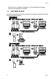
59125 Figure 2-3 2.5 2.5.1 Removing the RS485 Communications Option PCB or the Dual Setpoint Option PCB SELECTION OF INPUT TYPE 1 16 -DIN Controllers The selection of input type is accomplished on link jumpers on the CPU PCB. The CPU PCB may be either of two forms: (a) for a relay or SSR Output 1 (see Figure 2-4) or for a DC Output 1 (see Figure 2-5). Input type selection is as shown on the right. 2.5.
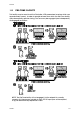
59125 2.6 2.6.1 SELECTION OF OUTPUT 1 TYPE 1 16 -DIN Controllers The required type of Output 1 is selected by Link Jumpers LJ4, LJ5, LJ6 and LJ7 on the Relay/SSR Output 1 CPU PCB (see Figure 2-4) or, on the DC Output 1 CPU PCB, Link Jumpers LJ8 and LJ9 (see Figure 2-5). Output type selection is as shown on the right. 2.6.2 -DIN and 81 -DIN Controllers 1 4 The required type of Output 1 is selected by Link Jumpers LJ4, LJ5, LJ6, LJ7, LJ8 and LJ9 on the PSU PCB (see Figure 2-7).
59125 Figure 2-4 CPU PCB (Relay/SSR Drive/Solid State Output 1) - 161 -DIN Controllers Figure 2-5 2-6 CPU PCB (DC Output 1) - 161 -DIN Controllers S054-2
59125 S054-2 Figure 2-6 CPU PCB - 41-DIN & 18-DIN Controllers Figure 2-7 PSU PCB - 41-DIN & 18-DIN Controllers 2-7
59125 Figure 2-8 2-8 DC Output Option PCB PCB (Output 2/Output 3) S054-2
59125 3 CONFIGURATION MODE 3.1 ENTRY INTO CONFIGURATION MODE See Figure 3-1. Figure 3-1 Entry into Configuration Mode NOTE: Changes to the value/setting of certain Configuration Mode parameters (e.g. input range, output use and type) will cause the Set Up Mode parameters to be automatically set to their default values the next time Set Up Mode is entered (see also Volume 1, beginning of Section 2).
59125 3.2 HARDWARE DEFINITION CODE This parameter is a special facility in Configuration Mode, which is used to represent the hardware fitted (input type, Output 1 type, Output 2 type and Output 3 type); this must be compatible with the hardware actually fitted. For access to, and adjustment of, the Hardware Definition Code, see Figure 3-2.
125 Table 3-1 Value 0 Hardware Definition Code - Input/Output Type Selection 1 2 3 4 5 7 8 Input Thermo- Linear Linear RTD/ Linear couple DC mA DC V DC mV Output 1 Relay SSR Drive DC DC 0 - 10V 0 - 20mA DC DC 0 - 5V 4 - 20mA Solid State Output Not Relay 2/3 fitted SSR Drive DC DC 0 - 10V 0 - 2-mA DC DC 0 - 5V 4 - 20mA Solid State NOTES: 1.
59125 Figure 3-3 3.4 Option Selection CONFIGURATION MODE PARAMETERS Parameter Identifier Input Range Description A four-digit code (see Appendix A).
59125 Parameter Identifier Alarm 2 Type Description Process High Alarm Process Low Alarm (default) Deviation Alarm Band Alarm No alarm Alarm Inhibit No alarms inhibited Alarm 1 inhibited Alarm 2 inhibited Both Alarm 1 & Alarm 2 inhibited S054-3 3-5
59125 Parameter Identifier Description Output 2 secondary control (COOL) output Output 2 Usage Alarm 2 hardware output, direct-acting. Available only if relay/SSR drive/solid state output. Alarm 2 hardware output, reverse-acting. Available only if relay, SSR drive or solid state output. Direct-acting output for Logical OR of Alarm 1 and Alarm 2. Available only if relay, SSR drive, or solid state output. Reverse-acting output for Logical OR of Alarm 1 and Alarm 2.
59125 Parameter Identifier Description Alarm 1 hardware output, direct-acting. Available only if relay/SSR drive/solid state output. Alarm 1 hardware output, reverse-acting. Available only if relay, SSR drive or solid state output. Direct-acting output for Logical OR of Alarm 1 and Alarm 2. Available only if relay, SSR drive, or solid state output. Reverse-acting output for Logical OR of Alarm 1 and Alarm 2. Available only if relay, SSR drive, or solid state output.
59125 Parameter Identifier Description Comms. Baud Rate Selectable: 1200, 2400, 4800, 9600 Baud Comms. Address Unique address assigned to the controller; in the range 1 - 32. Cold Junction Compensation Enable/Disable* Enabled (default) Lock Code 3.5 Disabled Read Only display of current four-digit Set Up Mode Lock Code. ALARM HYSTERESIS OUTPUTS An alarm hysteresis output is active only when both alarms are active; it becomes subsequently inactive only when both alarms become inactive.
59125 3.6 EXIT FROM CONFIGURATION MODE NOTE: An automatic exit to Operator Mode will be made if, in Configuration Mode, there is no front panel key activity for two minutes. The exit is made via the power-up self-test routines which include a lamp test.
59125 A PRODUCT SPECIFICATION A.1 UNIVERSAL INPUT General Maximum per Controller: One Input Sample Rate: Four samples/second Digital Input Filter: Time constant selectable from front panel 0.0 (i.e. OFF), 0.5 to 100.0 seconds in 0.5-second increments. Input Resolution: 14 bits approximately; always four times better than display resolution. Input Impedance: Greater than 100MΩ resistive (except for DC mA and V inputs).
59125 Type Input Range Dislayed Code Type Input Range Displayed Code L 0.0 - 205.7°C 1815 L 32 - 1403°F 1820 L 32.0 - 402.2°F 1816 B 211 - 3315°F 1934 L 0 - 450°C 1817 B 100 - 1824°C 1938 L 32 - 841°F 1818 N 0 - 1399°C 5371 L 0 - 762°C 1819 N 32 - 2550°F 5324 Calibration: Complies with BS4937, NBS125 and IEC584. Sensor Break Protection: Break detected within two seconds.
59125 Location of Break Input Type 1 4 -DIN or 81-DIN Controller 1 16 Alarm Operation -DIN Controller RTD Sensor or Terminal 1 Sensor or Terminal 6 As if Process Variable is over-range RTD Terminal 3 or 2 Terminal 4 or 5 As if Process Variable is under-range DC (mV) - - As if Process Variable is over-range DC Linear: Ranges Selectable from Front Panel (with displayed codes): Input Range Displayed Code Input Range Displayed Code 0 - 20mA 3413 0 - 5V 4445 4 - 20mA * 3414 1 - 5V
59125 Maximum Input Delay (OFF-ON): 1 second Minimum Input Delay (ON-OFF): 1 second A.3 OUTPUT 1 General Types Available: Relay (as standard), SSR drive, solid state and DC as options. Relay Contact Type: Single pole double throw (SPDT). Rating: 2A resistive at 120/240V AC. Lifetime: >500,000 operations at rated voltage/current. Isolation: Inherent. SSR Drive/TTL Drive Capability: SSR >4.2V DC into 1kΩ min. (161 -DIN) SSR > 4.3V into 250Ω min.
59125 Max. ON-State Voltage Drop @ Rated Current: 1.5V peak. Repetitive Peak OFF-state Voltage, Vdrm: 600V minimum. Resolution: Eight bits in 250mS (10 bits in 1 second typical, >10 bits in >1 second typical). Update Rate: Every control algorithm execution. Ranges: 0 - 20mA 4 - 20mA 0 - 10V 0 - 5V DC (Changes between V and mA ranges also require link jumper movement.
59125 SSR Drive/TTL Drive Capability: SSR >4.2V DC into 1kΩ min. (161 -DIN) SSR > 4.3V into 250Ω min. ( 41-DIN & 18-DIN) Isolation: Not isolated from input or other SSR drive outputs. Solid State Operating Voltage Range: 20 - 280Vrms (47 - 63Hz) Current Rating: 0.01 - 1A (full cycle rms on-state @ 25°C); derates linearly above 40°C to 0.5A @ 80°C. Max. Non-repetitive Surge Current (16.6ms): 25A peak Min. OFF-State Voltage: dv dt @ Rated 500V/µs Max.
59125 Isolation: Isolated from all other inputs and outputs. Range Selection Method: Link jumper or DIP switch and front panel code. A.5 OUTPUT 3 General Types Available: Relay, SSR drive, solid state and DC linear (Recorder Output only) Relay Contact Type: Single pole double throw (SPDT). Rating: 2A resistive at 120/240V AC. Lifetime: >500,000 operations at rated voltage/current. Isolation: Inherent. SSR Drive/TTL Drive Capability: SSR >4.2V DC into 1kΩ min. (161 -DIN) SSR > 4.
59125 Max. ON-State Voltage Drop @ Rated Current: 1.5V peak. Repetitive Peak OFF-state Voltage, Vdrm: 600V minimum. Resolution: Eight bits in 250mS (10 bits in 1 second typical, >10 bits in >1 second typical). Update Rate: Every control algorithm execution. Ranges: 0 - 20mA 4 - 20mA 0 - 10V 0 - 5V DC (Changes between V and mA require link jumper movement.
59125 ON/OFF Differential: 0.1% to 10.0% of input span. Auto/Manual Control: User-selectable with “bumpless” transfer into and out of Manual Control. Cycle Times: Selectable from 12s to 512 secs in binary steps. Setpoint Range: Limited by Setpoint Maximum and Setpoint Minimum. Setpoint Maximum: Limited by Setpoint and Range Maximum. Setpoint Minimum: Limited by Range Minimum and Setpoint. Setpoint Ramp: Ramp rate selectable 1 - 9999 LSDs per hour and infinite.
59125 Performance Under Reference Conditions Common Mode Rejection: >120dB at 50/60Hz giving negligible effect at up to 264V 50/60Hz. Series Mode Rejection: >500% of span (at 50/60Hz) causes negligible effect. DC Linear Inputs Measurement Accuracy: ±0.25% of span ±1LSD. Thermocouple Inputs Measurement Accuracy: ±0.25% of span ±1LSD. NOTE: Reduced performance with Type “B” Thermocouple between 100 - 600°C (212 - 1112°F). Linearisation Accuracy: Better than ±0.2°C any point, any 0.1°C range (±0.
59125 Operating Conditions Ambient Temperature (Operating): 0°C to 55°C Ambient Temperature (Storage): –20°C to 80°C Relative Humidity: 20% - 95% non-condensing Supply Voltage: 90 - 264V AC 50/60Hz (standard) 20 - 50V AC 50/60Hz or 22 - 65V DC (option) Source Resistance: 1000Ω maximum (thermocouple) Lead Resistance: 50Ω per lead maximum balanced (Pt100) Performance Under Operating Conditions Temperature Stability: 0.01% of span/°C change in ambient temperature.
59125 EMI Emissions: Certified to EN50081-1:1992 and EN50081-2:1994. Safety Considerations: Complies with EN61010-1:1993. Supply Voltage: 90 - 264V AC 50/60Hz (standard) 20 - 50V AC 50/60Hz or 22 - 65V DC (option) Power Consumption: 4 watts approximately. Front Panel Sealing: To IP66 (NEMA 4). A.
59125 Alphabetic Index - Volume 2 C Configuration Mode Entry into 3-1 Exit from 3-9 Controller Dimensions Removal/replacement Output 3 Type Selection of 2-5 Output Connections DC 1-7 Relay 1-7 SSR Drive 1-7 A-12 D Dual Setpoint Option PCB Removal/replacement Dual Setpoint Selection TTL-Compatible Input Voltage-Free Contacts P 2-3 1-7 1-7 H Panel-Mounting Cut-out dimensions (multiple installation) 1-1 Cut-out dimensions (single installation) 1-1 Maximum panel thickness 1-1 R Hardware Definition Code
59125 S Sensor Break Effect on outputs (DC linear inputs) A-3 Effect on outputs (RTD inputs) A-2 Effect on outputs (thermocouple inputs) Serial Communications Connections 1-8 Supply Connections 24V AC/DC Option 1-6 Mains (Line) voltage S056-IDX A-2 1-6 2