-DIN DUAL COLOUR DISPLAY DC PROCESS INDICATOR 1 8 Product Manual 59136-2
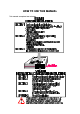
HOW TO USE THIS MANUAL This manual comprises two volumes:
59136 1 8 -DIN DUAL COLOUR DISPLAY DC PROCESS INDICATOR Product Manual Contents - Volume I 1 OPERATION MODE 1-1 1.1 FRONT PANEL 1-1 1.2 PARAMETER SEQUENCE 1-2 1.3 INPUT OVER-RANGE OR UNDER-RANGE 1-3 1.4 SENSOR BREAK 1-3 1.5 CHANGING AN ALARM VALUE 1-3 1.6 RESETTING A LATCHED ALARM 1-4 1.7 ALARM HYSTERESIS 1-4 1.8 SUMMARY OF PARAMETER IDENTIFIERS (SECONDARY DISPLAY) 1-4 2 PROGRAM MODE 2-1 2.1 ENTRY/EXIT 2-1 2.2 PARAMETER SELECTION 2-1 2.
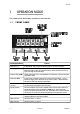
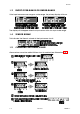
59136 1 OPERATION MODE This mode covers day-to-day operation of the Indicator. 1.1 FRONT PANEL Key/Display/Indicator Function Down key (Ú) In Edit Mode, decrements the flashing digit in the Primary Display. Scroll key (Ø) Puts Indicator into Edit Mode; in Edit Mode, selects digit to be altered (selected digit is flashing) in Primary Display. Wrap-around occurs from right-most digit to left-most digit. Program Key (PGM) Selects parameter to be viewed/edited.
9136 1.
59136 1.3 INPUT OVER-RANGE OR UNDER-RANGE If the input becomes over-range or under-range, the primary display will show: The display will disappear when the input returns within the input scale range. 1.4 SENSOR BREAK This indicates that there is a break in the input sensor circuit. 1.5 CHANGING AN ALARM VALUE Alarm values cannot be edited if Alarm Lock is enabled (see Subsection 2.4).
59136 1.6 RESETTING A LATCHED ALARM If Relay 1 is configured to act as a latched Alarm 1 relay, when this alarm is active, it can be reset by selecting the process variable display and then pressing the Reset (RST) key. The alarm will not be reset if the alarm condition exists at the time reset is attempted. 1.7 ALARM HYSTERESIS The Alarm Hysteresis parameter applies a hysteresis band on the “safe” side of the Alarm value.
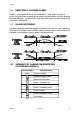
59136 2 2.1 PROGRAM MODE ENTRY/EXIT Use the Program (PGM) key in the same way to exit Program Mode (i.e. return to Operation Mode). 2.2 2.2.
59136 2.2.2 2.
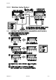
59136 2.4 PARAMETER SEQUENCE The Program Mode parameter sequence is as follows: Parameter Description (Primary Display) Parameter Description Adjustment Range Scaling Point 1 The first sensor input value 0.00% to 100.00% point (expressed as a percentage of input span) which is used to establish a curve for scaling sensor input values into engineering unit values. 0.00% Display Point 1 The engineering unit value −19999 to 99999 corresponding to Scaling Point 1. 0.00 Scaling Point 2 0.
59136 Parameter Description (Primary Display) Parameter Description Input Filter Time Constant Filters the input over a 0.0 (OFF) to 100.0 user-definable time period to minimise the effect on the process variable of any extraneous impulses 2.0 Communications Address The unique serial communications address of the instrument.
59136 3 SERIAL COMMUNICATIONS The Serial Communications option is a standard RS485 communications link. Up to 32 standard RS485 loads may be presented to a single loop on this link. Each Indicator presents ¼ standard, therefore up to 128 may be connected to a single loop (ignoring the load presented by the master device). However, addresses are restricted to the range 1 to 99. 3.1 DATA FORMAT/BAUD RATE Data format is fixed at one start bit, seven data bits, 1 parity bit (even parity) and 1 stop bit i.
59136 3.3.1 Form 1 Message The master device sends a Form 1 message to ascertain whether a specific communications address is occupied by an instrument. If there is an instrument at that address, a reply (with a positive acknowledgement) is received. If there is no instrument at that address or if there is a communications link failure, no reply is received. The message from the master device is of the form: Laa??* where aa is the address (a two-digit hexadecimal number).
59136 3.3.3 Form 3 Message This message implements the Parameter Write operation either on a single addressed instrument (address in the range 1 - 99) or broadcast to all instruments connected to the master device (i.e. using address 00). Note that, with the broadcast message, each slave instrument does not generate a reply.
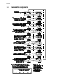
59136 Table 3-1 Identifier Hex. Parameter Identifiers and Adjustment Ranges Parameter Adjustment Range : 3A Process Variable Read Only (−19999 to 9999) ; 3B Total value Read Only (−19999 to 9999) < 3C Maximum Process Variable Read Only (−19999 to 9999) = 3D Minimum Process Variable Read Only (−19999 to 9999) > 3E Elapsed Alarm 1 Time Read Only (0 to 60000) @ 40 Reset Max. PV Write resets; Read always 0 A 41 Reset Min.
59136 3.4 ERROR CONDITIONS If a slave device detects a syntax error or parity error, it will not reply to the message; the master device should make up to two retries, applying the two-second No Reply timeout in each case. Parameter Read operations with parameter identifiers which are in the legal range but which are not applicable to the addressed instrument will have no effect on any parameter values and a positive acknowledgement will be returned.
59136 1 8 -DIN DUAL COLOUR DISPLAY DC PROCESS INDICATOR Product Manual Contents - Volume II 1 INSTALLATION 1-1 1.1 UNPACKING 1-1 1.2 PANEL-MOUNTING 1-1 1.3 CONNECTIONS AND WIRING 1-3 2 INTERNAL LINKS AND SWITCHES 2-1 2.1 REMOVING THE INDICATOR FROM ITS HOUSING 2-1 2.2 REMOVING/REPLACING THE RELAY 2/LINEAR OUTPUT OPTION PCBs 2-3 2.3 REMOVING/REPLACING THE RS485 SERIAL COMMUNICATIONS OPTION PCB/DIGITAL INPUT OPTION PCB 2-3 2.4 REPLACING THE INSTRUMENT IN ITS HOUSING 2-4 2.
59136 Appendices A PRODUCT SPECIFICATION A-1 A.1 DISPLAY A-1 A.2 SENSOR INPUT A-1 A.3 DIGITAL INPUT (OPTION) A-1 A.4 TRANSISTOR OUTPUTS A-2 A.5 RELAY 1 OUTPUT A-2 A.6 RELAY 2 OUTPUT (OPTION) A-2 A.7 LINEAR (RE-TRANSMITTED PV) OUTPUT (OPTION) A-2 A.8 SERIAL COMMUNICATIONS (OPTION) A-3 A.9 PERFORMANCE A-3 A.10 ENVIRONMENTAL A-4 A.
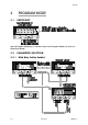
59136 1 INSTALLATION 1.1 UNPACKING 1. Remove the Indicator from its packing. The indicator is supplied with a panel gasket and push-fit fixing strap. Retain the packing for future use. 2. Examine the delivered items for damage or deficiencies. If any is found, notify the carrier immediately. 1.2 PANEL-MOUNTING The panel on which the Indicator is to be mounted must be rigid and may be up to 6mm (0.25 inches) thick. The cut-out required for a single Indicator is shown in Figure 1-1.
59136 Figure 1-3 1-2 Panel-mounting Volume II PM091-1
59136 1.3 CONNECTIONS AND WIRING The rear terminal connections are shown in Figure 1-4.
59136 1.3.1 Mains (Line) Supply The Indicator will operate on 90 - 264V AC 50/60Hz mains (line) supply. The power consumption is approximately 4 watts. CAUTION: This equipment is designed for installation in an enclosure which provides adequate protection against electric shock. Local regulations regarding electrical installation should be rigidly observed. Consideration should be given to prevention of access to the power terminations by unauthorised personnel.
59136 NOTE: This option and the Serial Communications option are mutually exclusive. 1.3.5 Relay Outputs Relay 1 is a standard feature; it is tied to Alarm 1. Relay 2 is an option; when fitted, it is tied to Alarm 2. The contacts are rated at 2A resistive @ 120/240V AC. 1.3.6 Linear Output This option provides a 10-bit linear output signal representing the process variable. The range of this output is selectable in Configuration Mode (see Subsection 3.4). 1.3.
59136 2 2.1 INTERNAL LINKS AND SWITCHES REMOVING THE INDICATOR FROM ITS HOUSING CAUTION: Before removing the Indicator from its housing, ensure that all power has been removed from the rear terminals. To remove the Indicator from its housing, simply grip the side edges of the front panel (there is a finger grip on each edge) and pull the instrument forward. This will release the rear terminals from their connectors in the housing and will give access to the PCBs.
59136 Figure 2-2 PM091-2 Removing the Relay 2/Linear Output Options PCBs Volume II 2-2
59136 2.2 REMOVING/REPLACING THE RELAY 2/LINEAR OUTPUT OPTION PCBs With the Indicator removed from its housing: 1. Gently push the rear ends of the CPU PCB and Power Supply PCB apart slightly, until the to tongues on each of the Relay 2 Option PCB and the Linear Output Option PCB become disengaged - see Figure 2-2B; the Relay 2 Option PCB tongues engage in holes in the Power Supply PCB and the Linear Output Option PCB tongues engage in holes in the CPU PCB. 2.
59136 2.4 REPLACING THE INSTRUMENT IN ITS HOUSING To replace the instrument in its housing, simply align the CPU PCB and Power Supply PCB with their guides and connectors in the housing and slowly but firmly push the instrument into position. CAUTION: Ensure that the instrument is correctly orientated. A stop will operate if an attempt is made to insert the instrument in the wrong orientation i.e. upside-down. This stop must not be over-ridden. 2.
59136 3 3.1 CONFIGURATION MODE ENTRY/EXIT Use these keys in the same way to exit from Configuration Mode. 3.2 3.2.
59136 3.2.2 3.
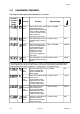
59136 3.4 PARAMETER SEQUENCE Parameter Description (Primary Display) Parameter Input Range Description Selects DC input range. Adjustment Range 0 - 20mA 4 - 20mA 10 - 50mA 0 - 5V 1 - 5V 0 - 10V 2 - 10V ±100mV ±1V ±10V Power Applicable to Supply DC-powered units only, Frequency this must be set to the mains (line) frequency for the site in order to ensure proper filtering of the input signal.
59136 Parameter Description (Primary Display) Parameter Description Adjustment Range Output 1 Usage Determines how NPN Output 1 and relay Output 1 operate. Alarm 1 nonlatching, direct action Alarm 1 nonlatching, reverse action Alarm 1, latching direct action Alarm 1, latching reverse action Logical OR Alarms 1 & 2, direct action Logical OR Alarms 1 & 2, reverse action Alarm 1 nonlatching direct action Output 2 Usage Determines how NPN Output 2 and Relay 2 operate.
59136 Parameter Description (Primary Display) Parameter Totaliser Scale Factor 3-5 Description Selects the timebase used for the totalisation calculation. This should be set to the same value as the timebase used for the engineering units which appear in the display. For example, if the display is calibrated in grams/minute, set this parameter to minutes.
59136 4 SERIAL COMMUNICATIONS CONFIGURATION MODE This section is a supplement to the information provided in Volume I, Section 3 and describes the Read/Write communications operations which can be performed in Configuration Mode. Table 4-1 Parameter Identifiers and Adjustment Ranges - Configuration Mode Identifier Hex.
59136 Table 4-1 Parameter Identifiers and Adjustment Ranges - Configuration Mode Identifier Hex.
59136 Table 4-2 Input Type Selection - Available Values DC Input Range Range Identifier Hex.
59136 APPENDIX A A.1 DISPLAY Type: Red/green, 7-segment LED, 5-digit primary display, 1-digit secondary display. Height: 0.71 inches (18mm) primary display 0.3 inches (7mm) secondary display Annunciators: Alarm 1 and Alarm 2 status. A.2 SENSOR INPUT Type: DC. Ranges selectable: 0 - 20mA, 4 - 20mA, 10 - 50mA 0 - 5V, 1 - 5V, 0 - 10V, 2 - 10V ±100mV, ±1V, ±10V Accuracy: Typical ±0.01% of span; ±0.05% max. Sample Rate: Every 100mS. Resolution: 14 bits.
59136 External Switch/Relay Contacts 50ΩMaximum Contact Resistance (Closure): Minimum Contact Resistance (Open): 5000Ω External TTL-Compatible Logic Signal Maximum Voltage (TTL) for “0”: 0.8V Minimum Voltage (TTL) for “0": -0.6V Minimum Voltage (TTL) for “1": 2.0V Maximum Voltage (TTL) for “1": 24.0V A.4 TRANSISTOR OUTPUTS Type: A.5 NPN open collector. Output tied to Alarm 1, Output 2 tied to Alarm 2. RELAY 1 OUTPUT Contact Type: Single pole double throw.
59136 Accuracy: 0.25% (mA @ 250W, V @ 2kW); degrades linearly to 0.5%. Resolution: 8 bits in 250mS (10 bits in 1 second typically). Update Rate: 4/second approximately. Load Impedance: mA ranges - 500Ω max. V ranges - 500Ω min. A.8 SERIAL COMMUNICATIONS (OPTION) Type: Serial asynchronous, UART to UART. Data Format: Open ASCII; One start bit, even parity, seven data bits, one stop bit. Physical Layer: RS485. Maximum Number of Zones: 99.
59136 Operating Conditions Ambient Temperature: 0°C to 55°C Relative Humidity: 20% - 95% non-condensing Performance Under Operating Conditions Temperature Stability: A.10 0.005% of span/°C change in ambient temperature. ENVIRONMENTAL EMI Susceptibility: Complies with EN50082-1:1992, EN50082-1:1995. NOTES: 1. For RF electromagnetic fields (10V/m 80% AM 1kHz), the reading accuracy may be impaired by up to −0.3% in the frequency band 87 to 109MHz. 2.