
User guide
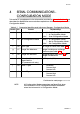

4 SERIAL COMMUNICATIONS -
CONFIGURATION MODE
This section is a supplement to the information provided in Volume I, Section 3 and
describes the Read/Write communications operations which can be performed in
Configuration Mode.
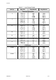
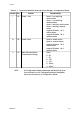
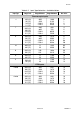
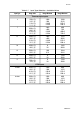
4-1 Volume II PM090-4
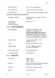
59135
Identifier Hex. Parameter Adjustment Range
d 64 Enter Configuration Mode Read:0 - Not in Configuration Mode
1 - In Configuration Mode
Write:1 - Enter Configuration Mode
e 65 Exit Configuration Mode Read:0 - In Configuration Mode
1 - Not in Configuration Mode
Write:1 - Exit Configuration Mode
f 66 Input Type For range of values, see Table 4-2.
g 67 Range Trim Maximum Range Trim Minimum to Range
Maximum (see Table 4-2)
h 68 Range Trim Minimum Range Minimum (see Table 4-2) to
Range Trim Maximum
i 69 Mains (Line) Frequency.
(Applicable to
DC-powered units only)
0 (50Hz) or 1 (60Hz)
j 6A Alarm 1 Type 0 No alarm
1 Process High
2 Process Low
k 6B Alarm 2 Type 0 No alarm
1 Process High
2 Process Low
Continued on next page ⇒⇒⇒⇒⇒
NOTE: All Configuration Mode parameters are Read Only when
the instrument is not in Configuration Mode, Read/Write
when the instrument is in Configuration Mode.
Table 4 -1 Parameter Identifiers and Adjustment Ranges - Configuration Mode