
User guide

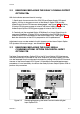

2.4 REPLACING THE INSTRUMENT IN ITS HOUSING
To replace the instrument in its housing, simply align the CPU PCB and Power
Supply PCB with their guides and connectors in the housing and slowly but firmly
push the instrument into position.
CAUTION: Ensure that the instrument is correctly orientated. A stop will
operate if an attempt is made to insert the instrument in the wrong
orientation i.e. upside-down. This stop must not be over-ridden.
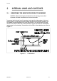
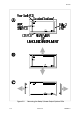
2.5 SELECTION OF LINEAR (RE-TRANSMISSION) OUTPUT
RANGE
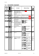
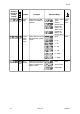
If the Linear Output Option PCB is fitted, link jumpers on that PCB are used to select
the output range (see Figure 2 -4 and Table 2 -1 ).
2 -4 Volume II PM090-2
59135
Figure 2-4 Linear Output Option PCB
Output Range Link Jumper Fitted
0 - 10V DC LJ8
0 - 20mA DC LJ9
0 - 5V DC LJ8
4 - 20mA DC LJ9
Table 2 -1 Linear Output Range
Selection