
User guide

1 INSTALLATION
1.1 UNPACKING
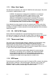
1. Remove the Indicator from its packing. The indicator is supplied with a
panel gasket and push-fit fixing strap. Retain the packing for future use.
2. Examine the delivered items for damage or deficiencies. If any is found,
notify the carrier immediately.
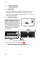
1.2 PANEL-MOUNTING
The panel on which the Indicator is to be
mounted must be rigid and may be up to
6mm (0.25 inches) thick. The cut-out
required for a single Indicator is shown in
Figure 1-1. Several indicators may be
mounted side-by-side in a single cut-out.
For n Indicators mounted side-by-side,
the cut-out dimensions would be (48n - 4)
millimetres or (1.89n - 0.16) inches. The
main dimensions of the Indicator are
shown in Figure 1 -2 .
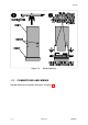
The panel-mounting procedure is shown in Figure 1 -3 .
CAUTION: Do not remove the panel gasket, as this may result in
inadequate clamping of the instrument in the panel.
PM090-1 Volume II 1-1
59135
Figure 1-1 Panel Cut-out
Figure 1-2 Main Dimensions