-DIN DUAL COLOUR DISPLAY TEMPERATURE INDICATOR 1 8 Product Manual 59135-2
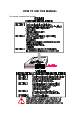
HOW TO USE THIS MANUAL This manual comprises two volumes:
59135 1 8 -DIN DUAL COLOUR DISPLAY TEMPERATURE INDICATOR Product Manual Contents - Volume I 1 OPERATION MODE 1-1 1.1 FRONT PANEL 1-1 1.2 PARAMETER SEQUENCE 1-2 1.3 INPUT OVER-RANGE OR UNDER-RANGE 1-3 1.4 SENSOR BREAK 1-3 1.5 CHANGING AN ALARM VALUE 1-3 1.6 RESETTING A LATCHED ALARM 1-4 1.7 ALARM HYSTERESIS 1-4 1.8 SUMMARY OF PARAMETER IDENTIFIERS (SECONDARY DISPLAY) 1-4 2 PROGRAM MODE 2-1 2.1 ENTRY/EXIT 2-1 2.2 PARAMETER SELECTION 2-1 2.
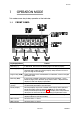
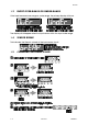
59135 1 OPERATION MODE This mode covers day-to-day operation of the Indicator. 1.1 FRONT PANEL Key/Display/Indicator Function Down key (Ú) In Edit Mode, decrements the flashing digit in the Primary Display. Scroll key (Ø) Puts Indicator into Edit Mode; in Edit Mode, selects digit to be altered (selected digit is flashing) in Primary Display. Wrap-around occurs from right-most digit to left-most digit. Program Key (PGM) Selects parameter to be viewed/edited.
9135 1.
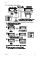
59135 1.3 INPUT OVER-RANGE OR UNDER-RANGE If the input becomes over-range or under-range, the primary display will show: The display will disappear when the input returns within the input scale range. 1.4 SENSOR BREAK This indicates that there is a break in the input sensor circuit. 1.
59135 1.6 RESETTING A LATCHED ALARM If Relay 1 is configured to act as a latched Alarm 1 relay, when this alarm is active, it can be reset by selecting the process variable display and then pressing the Reset (RST) key. The alarm will not be reset if the alarm condition exists at the time reset is attempted. 1.7 ALARM HYSTERESIS The Alarm Hysteresis parameter applies a hysteresis band on the “safe” side of the Alarm value.
59135 2 2.1 PROGRAM MODE ENTRY/EXIT Use the Program (PGM) key in the same way to exit Program Mode (i.e. return to Operation Mode). 2.2 2.2.
59135 2.2.2 2.
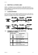
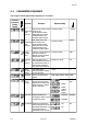
59135 2.4 PARAMETER SEQUENCE The Program Mode parameter sequence is as follows: Parameter Description (Primary Display) Parameter Description Retransmission Scale Minimum The lower end of the linear −19999 to 99999 scale for the re-transmission output, expressed as the value corresponding to the minimum output signal. Retransmission Scale Maximum The upper end of the linear scale for the re-transmission output, expressed as the value corresponding to the maximum output signal.
59135 3 SERIAL COMMUNICATIONS The Serial Communications option is a standard RS485 communications link. Up to 32 standard RS485 loads may be presented to a single loop on this link. Each Indicator presents ¼ standard, therefore up to 128 may be connected to a single loop (ignoring the load presented by the master device). However, addresses are restricted to the range 1 to 99. 3.1 DATA FORMAT/BAUD RATE Data format is fixed at one start bit, seven data bits, 1 parity bit (even parity) and 1 stop bit i.
59135 3.3.1 Form 1 Message The master device sends a Form 1 message to ascertain whether a specific communications address is occupied by an instrument. If there is an instrument at that address, a reply (with a positive acknowledgement) is received. If there is no instrument at that address or if there is a communications link failure, no reply is received. The message from the master device is of the form: Laa??* where aa is the address (a two-digit hexadecimal number).
59135 3.3.3 Form 3 Message This message implements the Parameter Write operation either on a single addressed instrument (address in the range 1 - 99) or broadcast to all instruments connected to the master device (i.e. using address 00). Note that, with the broadcast message, each slave instrument does not generate a reply.
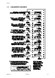
59135 Table 3-1 Identifier Hex. Parameter Identifiers and Adjustment Ranges Parameter Adjustment Range : 3A Process Variable Read Only (−19999 to 9999) < 3C Maximum Process Variable Read Only (−19999 to 9999) = 3D Minimum Process Variable Read Only (−19999 to 9999) > 3E Elapsed Alarm 1 Time Read Only (0 to 60000) @ 40 Reset Max. PV Write resets; Read always 0 A 41 Reset Min.
59135 1 8 -DIN DUAL COLOUR DISPLAY TEMPERATURE INDICATOR Product Manual Contents - Volume II The procedures described in this Volume must be undertaken only by technically-competent servicing personnel. 1 INSTALLATION 1-1 1.1 UNPACKING 1-1 1.2 PANEL-MOUNTING 1-1 1.3 CONNECTIONS AND WIRING 1-3 2 INTERNAL LINKS AND SWITCHES 2-1 2.1 REMOVING THE INDICATOR FROM ITS HOUSING 2-1 2.2 REMOVING/REPLACING THE RELAY 2/LINEAR OUTPUT OPTION PCBs 2-3 2.
59135 Appendices A PRODUCT SPECIFICATION A-1 A.1 DISPLAY A-1 A.2 SENSOR INPUT A-1 A.3 DIGITAL INPUT (OPTION) A-3 A.4 TRANSISTOR OUTPUTS A-3 A.5 RELAY 1 OUTPUT A-3 A.6 RELAY 2 OUTPUT (OPTION) A-4 A.7 LINEAR (RE-TRANSMITTED PV) OUTPUT (OPTION) A-4 A.8 SERIAL COMMUNICATIONS (OPTION) A-4 A.9 PERFORMANCE A-5 A.10 ENVIRONMENTAL A-7 A.
59135 1 INSTALLATION 1.1 UNPACKING 1. Remove the Indicator from its packing. The indicator is supplied with a panel gasket and push-fit fixing strap. Retain the packing for future use. 2. Examine the delivered items for damage or deficiencies. If any is found, notify the carrier immediately. 1.2 PANEL-MOUNTING The panel on which the Indicator is to be mounted must be rigid and may be up to 6mm (0.25 inches) thick. The cut-out required for a single Indicator is shown in Figure 1-1.
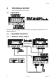
59135 Figure 1-3 1.3 Panel-mounting CONNECTIONS AND WIRING The rear terminal connections are shown in Figure 1-4.
59135 Figure 1-4 PM090-1 Rear Terminal Connections Volume II 1-3
59135 1.3.1 Mains (Line) Supply The Indicator will operate on 90 - 264V AC 50/60Hz mains (line) supply. The power consumption is approximately 4 watts. CAUTION: This equipment is designed for installation in an enclosure which provides adequate protection against electric shock. Local regulations regarding electrical installation should be rigidly observed. Consideration should be given to prevention of access to the power terminations by unauthorised personnel.
59135 1.3.5 Digital Input Option Terminals 16 and 17, when this option is fitted, may be used for external selection of the Security facility) which allows/prevents entry into Program Mode from the front panel. These terminals may be connected to (a) the voltage-free contacts of a switch or relay, or (b) a TTL-compatible voltage. With the Security option configured (see Subsection 3.
59135 Where several Indicators are connected to one master port, the master port transceiver in the active state should be capable of driving a load of 120kΩ per Indicator; the master port transceiver in the passive state must have pull-up/pull-down resistors of sufficiently low impedance to ensure that it remains in the quiescent state whilst supplying up to ±100µA each to the Indicator transceivers in the high impedance state. NOTE This option and the Digital Input option are mutually exclusive.
59135 2 INTERNAL LINKS AND SWITCHES 2.1 REMOVING THE INDICATOR FROM ITS HOUSING CAUTION: Before removing the Indicator from its housing, ensure that all power has been removed from the rear terminals. To remove the Indicator from its housing, simply grip the side edges of the front panel (there is a finger grip on each edge) and pull the instrument forward. This will release the rear terminals from their connectors in the housing and will give access to the PCBs.
59135 Figure 2-2 2-2 Removing the Relay 2/Linear Output Options PCBs Volume II PM090-2
59135 2.2 REMOVING/REPLACING THE RELAY 2/LINEAR OUTPUT OPTION PCBs With the Indicator removed from its housing: 1. Gently push the rear ends of the CPU PCB and Power Supply PCB apart slightly, until the to tongues on each of the Relay 2 Option PCB and the Linear Output Option PCB become disengaged - see Figure 2-2B; the Relay 2 Option PCB tongues engage in holes in the Power Supply PCB and the Linear Output Option PCB tongues engage in holes in the CPU PCB. 2.
59135 2.4 REPLACING THE INSTRUMENT IN ITS HOUSING To replace the instrument in its housing, simply align the CPU PCB and Power Supply PCB with their guides and connectors in the housing and slowly but firmly push the instrument into position. CAUTION: Ensure that the instrument is correctly orientated. A stop will operate if an attempt is made to insert the instrument in the wrong orientation i.e. upside-down. This stop must not be over-ridden. 2.
59135 3 3.1 CONFIGURATION MODE ENTRY/EXIT Use these keys in the same way to exit from Configuration Mode. 3.2 3.2.
59135 3.2.2 3.
59135 3.4 PARAMETER SEQUENCE Parameter Description (Primary Display) Parameter Description Adjustment Range Input Range Selects the input sensor type, resolution and display scale (°C or °F) by means of a code number. See Table 3-1. Range Trim High Adjusts the maximum Range Trim Low (see below) to Range range value of the input Range Max. (see Table 3-1). Max. type selected. Range Trim Low Adjusts the minimum Range Min.
59135 Parameter Description (Primary Display) Parameter Description Adjustment Range Output 2 Usage Determines how NPN Output 2 and Relay 2 operate.
59135 Table 3-1 Input Type Input Range Codes Range Code Range Minimum Range Maximum Thermocouple Inputs J 100 (°C) 101 (°F) 110 (°C) 111 (°F) –200 –328 –128.0 –198.4 1200 2192 537.0 998.6 T 200 (°C) 201 (°F) 210 (°C) 211 (°F) –240 –400 –128.0 –198.4 400 752 400.0 752.0 K 300 (°C) 301 (°F) 310 (°C) 311 (°F) –240 –400 –128.0 –198.4 1372 2502 537.0 998.
59135 4 SERIAL COMMUNICATIONS CONFIGURATION MODE This section is a supplement to the information provided in Volume I, Section 3 and describes the Read/Write communications operations which can be performed in Configuration Mode. Table 4-1 Parameter Identifiers and Adjustment Ranges - Configuration Mode Identifier Hex.
59135 Table 4-1 Parameter Identifiers and Adjustment Ranges - Configuration Mode Identifier Hex.
59135 Table 4-2 Input Type Input Type Selection - Available Values Range Code Range Minimum Range Maximum Hex. Value Thermocouple Inputs J 100 (°C) 101 (°F) 110 (°C) 111 (°F) –200 –328 –128.0 –198.4 1200 2192 537.0 998.6 0 1 2 3 T 200 (°C) 201 (°F) 210 (°C) 211 (°F) –240 –400 –128.0 –198.4 400 752 400.0 752.0 4 5 6 7 K 300 (°C) 301 (°F) 310 (°C) 311 (°F) –240 –400 –128.0 –198.4 1372 2502 537.0 998.
59135 APPENDIX A A.1 PRODUCT SPECIFICATION DISPLAY Type: Red/green, seven-segment LED, five-digit primary display, one-digit secondary display. Height: 0.71 inches (18mm) primary display 0.3 inches (7mm) secondary display Annunciators: Alarm 1 and Alarm 2 status. A.2 SENSOR INPUT Types: Type B, J, K, N, S and T thermocouples Three-wire and four-wire RTD Accuracy: 0.1% of span Sample Rate: Every 250mS. Resolution: 14 bits. Sensor Break Detection: Detected within two seconds.
59135 Table A-1 Input Type Input Type Selection - Available Values Range Code Range Minimum Range Maximum Thermocouple Inputs J 100 (°C) 101 (°F) 110 (°C) 111 (°F) –200 –328 –128.0 –198.4 1200 2192 537.0 998.6 T 200 (°C) 201 (°F) 210 (°C) 211 (°F) –240 –400 –128.0 –198.4 400 752 400.0 752.0 K 300 (°C) 301 (°F) 310 (°C) 311 (°F) –240 –400 –128.0 –198.4 1372 2502 537.0 998.
59135 A.3 DIGITAL INPUT (OPTION) Type: Voltage-free or TTL-compatible operation. May be connected to: External switch/relay contacts or TTL-compatible logic signal. Maximum Input delay (open - closed or “1" - “0" transition): 1 second Minimum Input delay (closed - open or “0" - “1" transition): 1 second External Switch/Relay Contacts Maximum Contact Resistance (Closure): 50 Minimum Contact Resistance (Open): 5000 External TTL-Compatible Logic Signal Maximum Voltage (TTL) for “0”: 0.
59135 Lifetime: >500,000 operations at rated voltage/current. Isolation: Inherent A.6 Contact Type: Single pole double throw. Rating: 5A resistive @ 120/240V AC Lifetime: >500,000 operations at rated voltage/current. Isolation: Inherent A.7 LINEAR (RE-TRANSMITTED PV) OUTPUT (OPTION) Ranges available: 0 - 5V, 1 - 5V, 0 - 10V, 2 - 10V, 0 - 20mA and 4 - 20mA. Accuracy: 0.25% (mA @ 250W, V @ 2kW); degrades linearly to 0.5%. Resolution: 8 bits in 250mS (10 bits in 1 second typically).
59135 A.9 PERFORMANCE Reference Conditions Ambient Temperature: 20°C ±2°C Relative Humidity: 60 - 70% Supply Voltage: 90 - 264V AC 50Hz Source Resistance: <10Ω for thermocouple input Lead Resistance: <0.1Ω/lead balanced (Pt100) Performance Under Reference Conditions Common Mode Rejection: >120dB at 50/60Hz giving negligible effect at up to 264V 50/60Hz. Series Mode Rejection: >500% of span (at 50/60Hz) causes negligible effect. Thermocouple Inputs Measurement Accuracy: ±0.05% typical, ±0.
59135 Relative Humidity: 20% - 95% non-condensing Source Resistance: 1000Ω maximum (thermocouple) Lead Resistance: 50Ω per lead maximum balanced (Pt100) Performance Under Operating Conditions Temperature Stability: 0.005% of span/°C change in ambient temperature. Cold Junction Compensation (thermocouple only): Better than ±1°C. A.10 EMI Susceptibility: Complies with EN50082-1:1992, EN50082-1:1995.