
Owner's manual
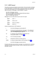

L {N} {P} {DATA} N *
where {DATA} is indeterminate. If the immediately-preceding message received
by the slave Controller was not a Type 3 message, the Type 4 message is ignored.
O075-5 5-5
PM-0075
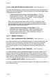
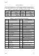
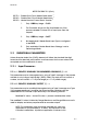
{DATA} Content Sign/Decimal Point Position {DATA} Content Sign/Decimal Point Position
abcd0 +abcd abcd5
−abcd
abcd1 +abc.d abcd6
−abc.d
abcd2 +ab.cd abcd7
−ab.cd
Table 5 -1 {DATA} Element - Sign and decimal Point Position
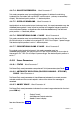
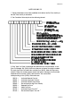
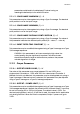
Identifier Parameter/Command Identifier Parameter/Command
A Setpoint High Limit W Output Power (Read Only if not in
Manual Control)
B Output 1 Power Limit Z Controller Commands
3
C Alarm 1 value [ Recorder Output Scale Max.
D Rate (Derivative Time Constant)
1
\ Recorder Output Scale Min.
E Alarm 2 value ] Scan Table
F ON/OFF Differential ^ Setpoint Ramp Rate
G Scale Range Max. (Read Only) a Alarm 1 Hysteresis value
H Scale Range Min. (Read Only) b Alarm 2 Hysteresis value
I Reset (Integral Time Constant)
1
c Heater Current High Scale Limit
J Manual Reset (Bias) d Heater Current Nominal Value
K Overlap/Deadband e Heater Current (Read Only)
L Controller Status
2
f High Heater Break Alarm value
M Process Variable g Low Heater Break Alarm value
N Output 1 Cycle Time h
AM Key Usage (Read Only)
O Output 2 Cycle Time i Control Setpoint value (Read Only)
P Proportional Band 1
1
j Soft Start Setpoint value
Q Scale Range Decimal Point Position
(Read Only)
k Soft Start Time value
S Setpoint value l Soft Start Time Remaining (Read
Only)
T Setpoint Low Limit m Input Filter Time Constant
U Proportional Band 2
1
v Process Variable Offset value
V Deviation value
Table 5 -2 Commands/Parameters and Identifiers