
Owner's manual


Alphabetical Index - Volume 2
A
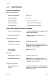
AC/DC (24V) Supply Option
Fuse rating 1-5
Terminal connections 1-5
Voltage range 1-5
Alarm 1 Type
Selection of 3-6
Alarm 2 Type
Selection of 3-7
Alarm Inhibit
Description of operation 3-7
Selection of 3-7
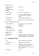
C
Cold Junction Compensation
Enabling/disabling 3-11
Cold Junction Compensation Disabled
Indication of
(Operator Mode) 3-11
Communications Address Range
MODBUS RTU protocol 3-11
Communications Protocol
Selection of 3-10
Configuration Mode 3-1
Automatic exit from 3-12
Entry into 3-1
Exit from 3-12
Controller Dimensions A-12
Current Transformer
Connections to 1-6
D
Dual Setpoint Selection
TTL-Compatible Input 1-6
Voltage-Free Contacts 1-6
Dual Setpoint/Quick Transfer
Option PCB
Removal/replacement 2-3
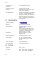
H
Hardware Definition Code
Adjustment of 3-3
Display of 3-2
Explanation of 3-3
Input/Output Type
selection 3-3
Hardware Option Selection 3-2,
3-4
Heater Break Alarm Strategy
Selection of 3-8
Heater Break Input Type 3-2
Selection of 3-5
Heater Current Input
Terminal connections 1-6
I
Inhibiting Alarms 3-7
Input Connections
Dual Setpoint Selection 1-6
RTD 1-6
Thermocouple 1-5
Input Range
Selection of 3-5
Installation 1-1
L
Link Jumpers
CPU PCB 2-3
DC Output 3
Option PCB 2-3
Lock Code
Display of 3-12
S075-IDX 1
PM-0075