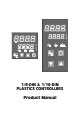
/8-DIN & 1/16-DIN PLASTICS CONTROLLERS Product Manual
PREFACE This manual comprises two volumes: Volume 1: This supports normal operation of the 1/8-DIN and 1/16-DIN Plastics Controllers. In normal operation, all actions taken by the user are to be in front of the front panel. Volume 2: This supports the installation, commissioning and configuring of the 1/8-DIN and 1/16-DIN Plastics Controllers. It is intended for use only by personnel who are trained, equipped and authorised to carry out these functions.
PM-0075 1 8 1 -DIN & 16 -DIN PLASTICS CONTROLLERS PRODUCT MANUAL VOLUME 1 OPERATING INSTRUCTIONS In normal operation, the operator must not remove the Controller from its housing or have unrestricted access to the rear terminals, as this would provide potential contact with hazardous live parts. Installation and configuration must be undertaken by technically-competent servicing personnel. This is covered in Volume 2 of this manual. Contents - Volume 1 1 INTRODUCTION 1-1 1.
PM-0075 2.10 MANUAL CONTROL MODE 2-5 2.11 HEATER CURRENT DISPLAY 2-5 2.12 SOFT START IN PROGRESS 2-6 2.13 QUICK TRANSFER OF HEATER CURRENT TO NOMINAL VALUE 2-6 2.14 PRE-TUNE 2-7 2.15 SELF-TUNE 2-7 2.16 TO VIEW THE HARDWARE DEFINITION CODE 2-8 3 SET UP MODE 3-1 3.1 ENTRY INTO SET UP MODE 3-1 3.2 SET UP MODE PARAMETERS 3-2 3.3 OPERATOR MODE DISPLAYS 3-17 3.4 TUNING THE CONTROLLER MANUALLY 3-18 3.5 SELF-TUNE 3-19 3.
PM-0075 1 INTRODUCTION The 161 -DIN and 18-DIN Plastics Controllers are economical, microprocessor-based temperature controller specially designed for use in plastics applications. They incorporate the latest in surface-mount and CMOS technology. The standard features include: • Dual four-digit LED display (upper display red, lower display green). • Thermocouple or three-wire RTD sensor input • Relay, SSR drive (10V) or solid state Output 1. • Input range selected from the front panel.
PM-0075 • Programmable input filter. • Alarm type selected from front panel. • Sensor Break protection. • Setpoint maximum and minimum limits (user-defined). and its many optional features include: • MODBUS and ASCII (selectable) communications with up to 128 zone address capability. • Output 2 - secondary (COOL) control output (relay, SSR drive or solid state), Alarm 2 output, Heater Break alarm output or logical combination of Alarm 1 and Alarm 2.
PM-0075 Operator Mode: This is the mode for day-to-day use. The parameters in this mode are freely available to the operator. The adjustment facilities available in this mode are dependent upon the settings of parameters in the Set Up Mode. 1.2 HOW IT WORKS The Plastics Controller is tailored towards plastics applications. The function of the Controller is best described in terms of the control it exercises over the process and the use of its alarms. 1.2.
PM-0075 1.2.2 Alarms Alarms allow early warning (and automatic corrective action, if necessary) in the event of abnormal process conditions - heater failure, sensor failure, human error etc. In addition to giving visual indication of such conditions, alarms can be connected to outputs; the Controller can intervene automatically as soon as it detects a problem in the plant. Two standard alarms are provided which warn if the process variable temperature moves outside prescribed limits.
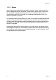
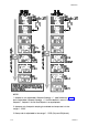
PM-0075 2 2.1 OPERATOR MODE INTRODUCTION This Section covers the routine operation of the Controller, once it has been installed and configured. The Controller front panel indicators and keys are shown in Figure 2-1. Figure 2-1 2.2 Front Panel Indicators and Control Keys SELECTING THE PARAMETER TO BE DISPLAYED/ADJUSTED After the Controller has performed its power-up self-test, the initial displays appear. The Scroll key may then be used to step through the available displays.
PM-0075 NOTES 1. Setpoint is not adjustable if Setpoint Strategy = 1 (see Subsection 3.2.40) but is adjustable if Setpoint Strategy = 2. Active setpoint is one of: Setpoint, Setpoint 1, Setpoint 2 or Soft Start Setpoint, as appropriate. 2. Appears only if setpoint ramping is enabled and ramp rate is in the range 1 - 9999. 3. Ramp rate is adjustable in the range 1 - 9999 (On) and Off (blank).
PM-0075 NOTES (continued) 4. Only appears if a Soft Start is in progress; see Subsection 2.4. 5. Appears only if an alarm is active; see Subsection 2.6. 6. In dual setpoint operation, the lower display distinguishes between the active and inactive setpoints in the following manner: 2.3 ADJUSTING THE DISPLAYED PARAMETER If either of these keys is held down for 10 seconds or more, the adjustment rate changes to “high speed” mode. 2.
PM-0075 Soft Start Time, Soft Start Setpoint and power limit are all adjustable in Set Up Mode (see Section 3). Soft Start is aborted at start-up if the process variable exceeds the Soft Start Setpoint. Setpoint ramping is inhibited during Soft Start. During a Soft Start, the Soft Start time remaining at any moment may be read from the front panel. 2.
PM-0075 2.8 SENSOR BREAK INDICATION If a break is detected in the sensor circuit, the upper display will show: The reaction of the outputs and alarms to a detected sensor break is dependent upon the input type. 2.9 OUTPUT TURN OFF (AM Key Usage Set Up parameter = ) Press the AM key to switch between automatic control and the control output(s) being permanently turned off. A return to automatic control is via a bumpless transfer.
PM-0075 2.12 SOFT START IN PROGRESS If a Soft Start is in progress, the heater current display will show (in the lower display): The normal heater current display will be restored as soon as the Soft Start time has expired. 2.13 QUICK TRANSFER OF HEATER CURRENT TO NOMINAL VALUE The nominal value of the heater current is manually adjustable in Set Up Mode.
PM-0075 2.14 PRE-TUNE To tune approximately the Controller’s PID parameters, activate Pre-Tune: The AT indicator will flash whilst Pre-Tune is operating. To dis-engage Pre-Tune, repeat this procedure (the AT indicator will go OFF). 2.15 SELF-TUNE To optimise tuning whilst the Controller is operating, activate Self-Tune: To dis-engage Self-Tune, repeat this procedure (the AT indicator will go OFF).
PM-0075 2.16 TO VIEW THE HARDWARE DEFINITION CODE The Hardware Definition Code indicates the input type and output type(s) fitted (see below). To view this Code: The same key action causes a return to the normal Operator Mode display. An automatic return is made to the normal Operator Mode display after 30 seconds.
PM-0075 3 SET UP MODE 3.1 ENTRY INTO SET UP MODE NOTE: If the upper display shows: (i.e. all decimal point positions ON), parameters are at their default values, possibly due to a change in Controller configuration. To cancel this indication, adjust any Set Up Mode parameter (see below). It is recommended that all configuration parameters are finalised before any adjustments are made to Set Up Mode parameters.
PM-0075 3.2 SET UP MODE PARAMETERS Table 3-1 Parameter Legend Set Up Parameters Adjustment Range Default Input Filter Time Constant OFF, 0.5s to 100.0s In 0.5s increments 2.0s Process Variable Offset ±input span of Controller 0 Output Power 0 to 100% Read Only 0 to 100% Read Only 0.0% to 999.9% of input span 10.0% 0.0% to 999.9% of input span 10.0% Reset (Integral Time Constant) 1 1s to 99m 59s and OFF.
PM-0075 Table 3-1 (Cont.) Parameter Legend Set Up Parameters Adjustment Range Default Recorder Output Scale Max. −1999 to 9999 Range Max. Recorder Output Scale Min. -1999 to 9999 Range Min. 0 to 100% of full power 100% 1 Output 1 Power Limit Output 1 Cycle Time 0.5, 1, 2, 4, 8, 16, 32, 64, 128, 32seconds 256 or 512 seconds Output 2 Cycle Time 0.5, 1, 2, 4, 8, 16, 32, 64, 128, 32seconds 256 or 512 seconds Process High Alarm 1 value 3 Range Min. To Range Max. Range Max.
PM-0075 Table 3-1 (Cont.) Parameter Legend Set Up Parameters Adjustment Range Default High Heater Break Alarm level (% or amount above nominal heater current) 1% to 100% (of nominal) and 0 (OFF) or 0.1A/1A to Heater Current High Scale Limit 0 (OFF) Short Circuit Heater Break Alarm 10 0 (disabled) or 1 (enabled) 1 (enabled) Soft Start Setpoint Range Min. To Range Max. Range Min.
PM-0075 NOTES ON TABLE 3-1 1. These parameters are not operative if the Proportional Band = 0. 2. Switching differential with ON/OFF Control Output. 3. These parameters are optional; only one legend will appear for each alarm. 4. Only applicable if Output 2 is fitted. 5. Appears only if ramp rate rp is not switched OFF. 6. Applicable only if the Communications Option PCB is fitted. 7. Does not appear in Operator Mode unless rPEN = 1. 8.
PM-0075 The offset process variable value is used for all PV-dependent functions (control, display, alarm, recorder output etc.). NOTE: This parameter value should be chosen with care. Any adjustment to this parameter is, in effect, a calibration adjustment. Injudicious application of values to this parameter could lead to the displayed process variable value bearing no meaningful relationship to the actual process variable value. There is no front panel indication when this parameter is in effect (i.e.
PM-0075 Figure 3-1 O075-3 Proportional Band and Deadband/Overlap 3-7
PM-0075 3.2.8 Rate (Derivative Time Constant) This parameter is adjustable in the range 00 seconds to 99 minutes 59 seconds. This parameter is not applicable if Proportional Band 1 (see Subsection 3.2.5) is set to 0 (ON/OFF control). 3.2.9 Overlap/Deadband This defines the portion of the Proportional Band (Proportional Band 1 + Proportional Band 2) over which both outputs are active (or, in the case of a deadband, neither output is active).
PM-0075 process being controlled. The Setpoint Low Limit may be adjusted between the Input Range Minimum and the current setpoint value. The default value is Input Range Minimum. 3.2.14 Recorder Output Scale Maximum This parameter defines the value of process variable or setpoint (whichever is applicable) at which the Recorder Output reaches its maximum value; for example, for a 0 - 5V Recorder Output, this value corresponds to 5V. It may be adjusted within the range –1999 to 9999.
PM-0075 control requirements) in order to maximise relay life. For an SSR Drive Output, the cycle time may have a lower value (and thus satisfy the requirements of a fast-changing process variable e.g. flow or pressure). The permitted range of values is: 0.5, 1, 2, 4, 8, 16, 32, 64, 128, 256 or 512 seconds The default value is 32 seconds. This parameter is not applicable if Proportional Band 1 is set to 0. 3.2.
PM-0075 Figure 3-2 O075-3 Alarm Operation 3-11
PM-0075 3.2.22 Deviation (High/Low) Alarm 1 Value This parameter, applicable only if Alarm 1 is selected to be a Deviation High/Low Alarm, defines a value above (positive value - Deviation High alarm) or below (negative value - Deviation Low alarm) the setpoint; if the process variable deviates from the setpoint by a margin greater than that defined by this parameter, Alarm 1 goes active. This parameter value may be adjusted in the range ±(input range) from setpoint.
PM-0075 Figure 3-3 O075-3 Alarm Hysteresis Operation 3-13
PM-0075 3.2.27 Deviation (High/Low) Alarm 2 Value This parameter, applicable only if Alarm 2 is selected to be a Deviation High/Low Alarm, defines a value above (positive value - Deviation High alarm) or below (negative value - Deviation Low alarm) the setpoint; if the process variable deviates from the setpoint by a margin greater than that defined by this parameter, Alarm 2 goes active. This parameter value may be adjusted in the range ±(input range) from setpoint.
PM-0075 If Heater Break Alarm Strategy = Percentage Mode: 0 - 100% of Heater Nominal Current (0 = OFF - value display blank, Low Heater Alarm forced inactive). Default value = 20% below heater nominal current. Hysteresis is half the Low Heater Break Alarm value. If Heater Break Alarm Strategy = Absolute Mode: 0.1A/1A (dependent upon display resolution) - Heater Current High Scale Limit and 0 (OFF) - value display blank, Low Heater Alarm forced inactive. Default value = 0 (OFF). Hysteresis is 0.5A for 0.
PM-0075 When the Soft Start Time expires, the normal setpoint value is restored. Default value is Input Range Minimum. 3.2.35 Soft Start Time This parameter defines the duration of the Soft Start from power-up. After this time expires, normal setpoint values will prevail. This parameter is adjustable in the range 15 seconds to 59 minutes 45 seconds (in 15-second increments) and OFF (less than 15 seconds); the default value is OFF. 3.2.
PM-0075 3.2.39 Communications Write Enable/Disable This parameter enables/disables Write operations (i.e. the changing of parameter values/settings) via the RS485 communications link, if the Communications Option PCB is fitted (0 = Disabled, 1 = Enabled). The default setting is 1 (Enabled). Parameters can be interrogated via the link, regardless of the setting of this parameter. 3.2.
PM-0075 3.4 TUNING THE CONTROLLER MANUALLY 3.4.1 Controllers Fitted with Output 1 Only Before starting to tune the Controller to the load, check that the Setpoint High and Low Limits (SPhi and SPLo) are set to safe levels - see Subsections 3.2.12 and 3.2.13. The following simple technique may be used to determine values for proportional band (Pb1), derivative time constant (rAtE) and integral time constant (rSEt).
PM-0075 Figure 3-4 3.4.2 Manual Tuning Parameters (Output 1 only) Controllers Fitted with Output 1 and Output 2 Before starting to tune the Controller to the load, check that the Setpoint High and Low Limits (SPhi and SPLo) are set to safe levels - see Subsections 3.2.12 and 3.2.13. The following simple technique may be used to determine values for proportional band (Pb1), derivative time constant (rAtE) and integral time constant (rSEt).
PM-0075 3.6 EXIT FROM SET UP MODE To leave Set Up Mode, select the initial Operator Mode display (process variable/setpoint) then depress the Raise and Function keys simultaneously, whereupon the Controller will return to Operator Mode. NOTE: An automatic return to Operator mode will be executed if there is no key activity in Set Up Mode for two minutes.
PM-0075 4 MODBUS RTU COMMUNICATIONS The Plastics Controller may be equipped with two-wire RS485-compatible serial communications, by which means communication may occur between the Controller and a master device (e.g. a computer or terminal). 4.1 COMMUNICATIONS WRITE ENABLE/DISABLE When Communications Write operations are enabled (in Set Up Mode - see Subsection 3.2.39), the Controller parameters may be adjusted by the master device via the serial communications link.
PM-0075 Function MODBUS Function Number Read Coil Status (Read n Bits) 01/02 Read Holding Registers (Read n Words) 03/04 Force Single Coil (Write 1 Bit) 05 Preset Single Register (Write 1 Word) 06 Loopback Diagnostic Test 08 Preset Multiple Registers (Write n Words) 16 The Controller will identify itself in response to a Read Holding Registers message which enquires the values of word parameters 121 and 122 (see Table 4-2); MODBUS Function 17 (Report Slave ID) is not supported. 4.3.
PM-0075 (b) because only the remainder is of interest, the right-most (most significant) bit can be discarded. Thus, the polynomial has the value Hex A001. The CRC algorithm is shown in Figure 4-1.
PM-0075 Read Coil Status (Read n Bits) - 01/02 The message sent to the Controller consists of eight bytes: The normal reply will echo the first two characters of the message received followed by a single-byte data byte count (which will not include itself or the CRC). For this message, there will be one byte of data per eight bits-worth of information requested, with the least significant bit of the first data byte transmitted depicting the state of the lowest-numbered bit required.
PM-0075 Loopback Diagnostic Test - 08 This is an eight-byte message comprising the usual pre-amble, a two-byte diagnostic code, two bytes of data and the CRC16 bytes: The only diagnostic code supported is 00. The normal response is an exact echo of the received message. Preset Multiple Registers (Write n Words) - 16 This is an eleven-byte message. only one parameter may be written for each received message.
PM-0075 connected, the limit is dictated by the sum total of all the RS485 receiver loadings. 4.3.4 Bit Parameters The bit parameters are shown in Table 4-1. 4.3.5 Word Parameters The word parameters are shown in Table 4-2.
PM-0075 Table 4-1 Parameter MODBUS Bit Parameters No. Notes Comms. Write Status 1 Read Only. 1 = enabled, 0 = disabled Auto/Manual Control 2 1 = Manual, 0 = Auto 4 3 1 = activate(d), 0 = dis-engage(d) 4 1 = activate(d), 0 = dis-engage(d) Alarm 1 Status 5 Read Only. 1 = active, 0 = inactive Alarm 2 Status 6 Read Only. 1 = active, 0 = inactive Setpoint Ramp Enable/Disable 7 1 = enable(d), 0 = disable(d) 8 Read Only.
PM-0075 Table 4-2 Parameter MODBUS Word Parameters No.
PM-0075 Table 4-3 MODBUS Word Parameters (Cont.) Parameter No. Notes Low Heater Break Alarm value 31 0 - 100% and OFF or 0.1A/1A Heater Current High Scale Limit (see Subsection 4.4.6.5) High Heater Break Alarm value 32 0 - 100% and OFF or 0.1A/1A Heater Current High Scale Limit (see Subsection 4.4.6.6) Heater Current 33 Read Only AM Key Usage 34 Read Only Alarm 1 Hysteresis 35 1 - 250 or 0.1 - 25.0 (as per Heater Current High Scale Limit) Alarm 2 Hysteresis 36 1 - 250 or 0.1 - 25.
PM-0075 4.4.1.2 PROCESS VARIABLE OFFSET - Word Parameter 26 This word parameter may be modified/interrogated. It modifies the actual process variable value (as measured at the Controller’s input terminals) in the following manner: Modified PV value = Actual PV value + process variable offset value The modified PV value is limited by Range Maximum and Range Minimum and is used for display and alarm purposes and for recorder outputs. NOTE: This parameter value should be selected with care.
PM-0075 Manual control is not selected, this word parameter is Read Only; if Manual control is selected, this parameter may be adjusted. 4.4.2.2 OUTPUT 1 POWER LIMIT - Word Parameter 20 This word parameter may be modified/interrogated. It defines the power limit for Output 1 and may be set in the range 0% to 100% of full power. The default value is 100%. The decimal point position is fixed at 1 decimal place. If Soft Start is used, this power limit is applicable only during Soft Start.
PM-0075 4.4.2.6 RECORDER OUTPUT MINIMUM VALUE - Word Parameter 28 This word parameter may be modified/interrogated. It defines the minimum scale value for the Controller’s Recorder Output and may be adjusted within the range –1999 to 9999. This value corresponds to the Input Scale Minimum and the decimal point position will always be the same as that for the input. If this parameter is set to a value greater than the Recorder Output Maximum Value, the sense of the Recorder Output is reversed. 4.4.
PM-0075 1 - 9999 increments per hour or 0 (ramping OFF). The decimal point position is as for the input range. 4.4.4.3 SETPOINT HIGH LIMIT - Word Parameter 22 This word parameter may be modified/interrogated. It defines the maximum value which may be assigned to the setpoint. The default value is Input Range Maximum. The permissible range is between the current setpoint value and Input Range Maximum. The decimal point position is as for the input range. 4.4.4.
PM-0075 4.4.6 Alarm Parameters 4.4.6.1 ALARM 1 VALUE - Word Parameter 13 This word parameter may be modified/interrogated. It defines the level at which Alarm 1 will go active. The decimal point position is as for the input range. 4.4.6.2 ALARM 1 HYSTERESIS - Word Parameter 35 This word parameter applies a hysteresis band on the "safe" side of the Alarm 1 value.
PM-0075 4.4.6.6 HIGH HEATER BREAK ALARM VALUE - Word Parameter 32 This word parameter defines a heater current value above which the High Heater Break Alarm will become active. It may be adjusted in the following ranges above the Heater Nominal Current: If Heater Break Alarm Strategy = Percentage Mode: 0 - 100% of Heater Nominal Current (0 = OFF - value display blank, High Heater Break Alarm forced inactive). Default value = 0 (OFF). Hysteresis is half the High Heater Break Alarm value.
PM-0075 4.4.7.4 ON/OFF DIFFERENTIAL - Word Parameter 17 This word parameter may be modified/interrogated. It defines the switching hysteresis (for Controllers with an ON/OFF control output - primary or secondary output). The decimal point position = 1 decimal place. 4.4.7.5 OVERLAP/DEADBAND - Word Parameter 16 Applicable to a dual control output instrument only, this word parameter may be modified/interrogated.
PM-0075 5 ASCII COMMUNICATIONS The Plastics Controller may be equipped with a two-wire RS485-compatible serial communications facility, by which means communication may occur between the Controller and a master device (e.g. a computer or terminal). 5.1 COMMUNICATIONS WRITE ENABLE/DISABLE When Communication Writes are enabled (in Set Up Mode - see Subsection 3.2.39), the Controller parameters may be adjusted by the master device via the serial communications link.
PM-0075 5.2.3 ASCII Protocol The protocol assumes half duplex communications. All communication is initiated by the master device. The master sends a command or query to the addressed slave and the slave replies with an acknowledgement of the command or the reply to the query.
PM-0075 5.2.4 Type 1 Message L {N} ? ? * This message is used by the master device to determine whether the addressed slave Controller is active. The reply from the slave Controller, if it is active, is L {N} ? A * An inactive Controller will give no reply. 5.2.5 Type 2 Message L {N} {P} {C} * This type of message is used by the master device to interrogate or modify a parameter in the addressed Controller.
PM-0075 Scan Tables A parameter identifier character “]” in the message from the master device indicates that a “Scan Table” operation is required. This provides a facility for interrogating the values of a group of parameters and status in a single message from the master device.
PM-0075 L {N} {P} {DATA} N * where {DATA} is indeterminate. If the immediately-preceding message received by the slave Controller was not a Type 3 message, the Type 4 message is ignored. Table 5-1 {DATA} Content {DATA} Element - Sign and decimal Point Position Sign/Decimal Point Position abcd0 +abcd abcd1 −abcd −abc.d abcd6 +ab.cd Table 5-2 Sign/Decimal Point Position abcd5 +abc.d abcd2 Identifier {DATA} Content −ab.
PM-0075 NOTES ON TABLE 5-2 1. These parameters cannot be modified whilst either the Pre-Tune facility or the Self-Tune facility is activated. 2. The Controller Status byte has the following format: 3. Only Type 3 or Type 4 messages are allowed with this parameter. In the Type 3 message, the {DATA} field must be one of eleven five-digit numbers. The reply from the Controller also contains the {DATA} field with the same content.
PM-0075 NOTES ON TABLE 5-2 (Cont.) 00170 = Enable Short Circuit Heater Break Alarm 4 00180 = Disable Short Circuit Heater Break Alarm 4 00190 = Heater Nominal Current Quick Transfer 5 5.3 1. Only if AM Key Usage = PoEn 2. The Controller will go into Pre-Tune Mode only if the process variable is at least 5% of input span from the setpoint. 3. Only if AM Key Usage = OoFF. 4. Not applicable if Heater Break Input Type is configured to be SCRi. 5.
PM-0075 parameter could lead to the displayed PV value having no meaningful relationship to the actual PV value. 5.3.1.3 SCALE RANGE MAXIMUM {P} = G This parameter may be interrogated only using a Type 2 message. The decimal point position is as for the input range. 5.3.1.4 SCALE RANGE MINIMUM {P} = H This parameter may be interrogated only using a Type 2 message. The decimal point position is as for the input range. 5.3.1.
PM-0075 5.3.2.3 OUTPUT 1 CYCLE TIME {P} = N This parameter may be modified/interrogated using a Type 2 message or a Type 3/4 message sequence. The value to which this is set is dependent upon the output type and the nature of the process to be controlled. For relay outputs, this parameter should be set to as large a value as possible (consistent with satisfactory control of the process) in order that the life of the relay be maximised. For SSR Drive and Solid State outputs, lower values may be used.
PM-0075 5.3.3 Heater Current Parameters 5.3.3.1 HEATER CURRENT HIGH SCALE LIMIT {P} = c This parameter defines the full scale value for the heater currrent range and may be modified/interrogated using a Type 3/4 message sequence only. It may be adjusted from 10.0A to 20.0A in 0.1A increments, and then from 21A to 100A in 1A increments. The default value is 50A. Heater current range minimum is fixed at 0A.
PM-0075 5.3.4.3 SETPOINT HIGH LIMIT {P} = A This parameter may be modified/interrogated using a Type 2 message or a Type 3/4 message sequence. It defines the maximum value which may be assigned to the setpoint. The default value is Input Range Maximum. The permissible range is between the current setpoint value and Input Range Maximum. The decimal point position is as for the input range. 5.3.4.
PM-0075 5.3.6 Alarm Parameters 5.3.6.1 ALARM 1 VALUE {P} = C This parameter may be modified/interrogated using a Type 2 message or a Type 3/4 message sequence. It defines the level at which Alarm 1 will go active. The decimal point position is as for the input range. 5.3.6.2 ALARM 1 HYSTERESIS {P} = a This parameter, which may be modified/interrogated using a Type 2 message or a Type 3/4 message sequence, applies a hysteresis band on the “safe” side of the Alarm 1 value.
PM-0075 If Heater Break Alarm Strategy = Absolute Mode: 0.1A/1A (dependent upon display resolution) - Heater Current High Scale Limit and 0 (OFF) - value display blank, Low Heater Alarm forced inactive. Default value = 0 (OFF). Hysteresis is 0.5A for 0.1A resolution and 2A for 1A resolution. 5.3.6.
PM-0075 5.3.7.3 MANUAL RESET (BIAS) {P} = J This parameter may be modified/interrogated using a Type 2 message or a Type 3/4 message sequence. The decimal point position is as for the input range. 5.3.7.4 ON/OFF DIFFERENTIAL {P} = F This parameter may be modified/interrogated using a Type 2 message or a Type 3/4 message sequence. It defines the switching hysteresis (for Controllers with an ON/OFF control output - primary or secondary output). The decimal point position = 1. 5.3.7.
PM-0075 5.3.8.3 AM KEY USAGE {P} = h This parameter, which may be interrogated only using a Type 2 message, indicates the usage selected for the front panel AM key: 0 1 2 - Output Turnoff - Auto/Manual Control selection - Heater Current display See also Subsection 3.2.37. 5.3.8.4 SCAN TABLE {P} = ] The Scan Table operation takes the form of a Type 2 interrogation command which accesses a set of information (held in the {DATA} element in the response).
PM-0075 Alphabetical Index - Volume 1 A Active Alarm Indication of 2-4 Active Setpoint Indication of 2-3 Address Range ASCII protocol 5-2 Address Range - Enhanced RS485 Option MODBUS RTU protocol 4-5 Address Range - Standard RS485 Option MODBUS RTU protocol 4-5 Alarm 1 Hysteresis 3-12, 4-14, 5-12 Alarm 1 Value 4-14, 5-12 Alarm 2 Hysteresis 3-14, 4-14, 5-12 Alarm 2 Value 4-14, 5-12 Alarm Status Display of 2-4 Alarms Summary description 1-4 AM Key Usage 3-16, 4-16, 5-15 To select automatic control/output tur
PM-0075 D Data Padding 4-4 Deadband 3-8, 4-16, 5-14 Decimal Point Position 4-10 Derivative Time Constant 4-15, 5-13 Derivative Time Constant See Also Rate Deviation Alarm 1 3-12 Deviation Alarm 2 3-14 E Error Responses ASCII protocol 5-15 MODBUS RTU protocol 4-5 Exception Responses MODBUS RTU protocol 4-5 F Heater Current Display Selection of (Operator Mode) 2-5 Selection/de-selection 2-5 Heater Current High Scale Limit 3-14, 4-12, 5-10 Heater Nominal Current 3-14, 4-12, 5-10 Heater Nominal Current Auto
PM-0075 L Line Turn-Round ASCII protocol 5-1 MODBUS RTU protocol 4-1 Lock Value 3-17 Low Heater Break Alarm 3-14 Automatic setting to default 3-14 Low Heater Break Alarm Value 4-14, 5-12 M Manual Control Mode Decsription of operation 2-5 Manual Control Mode Selection of 2-5 Manual Reset 4-15, 5-14 See Also Bias Manual Tuning Controllers with Output 1 and Output 2 3-19 Controllers with Output 1 only 3-18 Dual output 3-19 Single Output 3-18 Message Formats MODBUS RTU protocol 4-2 MODBUS Functions Supported
PM-0075 Sensor Break Indication of 2-5 4-16, Serial Communications 4-1 Enabling/disabling 4-16, End of Message character 5-2 Message Types 5-2 Q Scan Tables command Start of Message Quick Transfer character 5-2 Heater current to Type 2 message 5-3 nominal value 2-6 Type 3 message 5-4 Type 4 message 5-4 R Set Up Mode Automatic exit from Rate 4-15, 5-13 Entry into 3-1 See Also Derivative Time Constant Exit from 3-20 Recorder Output Maximum Summary description Value 4-11 Set Up Parameters at Default Recorder
PM-0075 Soft Start Time remaining Soft Start Time Remaining 4-13 5-11 T Thermal shocks Avoidance of 1-3 Three-Term Control 1-3 Time-Proportioning 1-3 Two-wire Communications 4-1 W Write Operations MODBUS RTU protocol 5 4-1 O075-IDX
PM-0075 1 8 1 -DIN & 16 -DIN PLASTICS CONTROLLERS PRODUCT MANUAL VOLUME 2 INSTALLATION & CONFIGURATION INSTRUCTIONS The procedures described in this Volume must be undertaken only by technically-competent servicing personnel. Contents - Volume 2 1 INSTALLATION 1-1 1.1 UNPACKING PROCEDURE 1-1 1.2 PANEL-MOUNTING THE CONTROLLER 1-1 1.3 CONNECTIONS AND WIRING 1-3 INTERNAL LINKS AND SWITCHES 2-1 2 2.1 REMOVING THE CONTROLLER FROM ITS HOUSING 2-1 2.
PM-0075 3.2 HARDWARE DEFINITION CODE, OPTION SELECTION AND HEATER BREAK INPUT TYPE 3-2 3.3 CONFIGURATION MODE PARAMETERS 3-5 3.4 EXIT FROM CONFIGURATION MODE 3-12 APPENDIX A PRODUCT SPECIFICATION A-1 A.1 UNIVERSAL INPUT A.2 DUAL SETPOINT/QUICK TRANSFER SELECTION INPUT (OPTION) A-3 A.3 HEATER CURRENT INPUT A-3 A.4 OUTPUT 1 A-4 A.5 OUTPUT 2 A-5 A.6 OUTPUT 3 A-6 A.7 LOOP CONTROL A-7 A.8 SOFT START A-8 A.9 PV ALARMS A-9 A.10 HEATER BREAK ALARMS A-9 A.
PM-0075 1 INSTALLATION 1.1 UNPACKING PROCEDURE 1. Remove the Controller from its packing. The Controller is supplied with a panel gasket and push-fit fixing strap. Retain the packing for future use, should it be necessary to transport the Controller to a different site or to return it to the supplier for repair/testing. 2. Examine the delivered items for damage or deficiencies. If any is found, notify the carrier immediately. 1.
PM-0075 Figure 1-2 Main Dimensions To panel-mount the Controller, proceed as shown in Figure 1-3. NOTE: Do not remove the panel gasket, as this may result in inadequate clamping of the instrument in the panel. Once the Controller is installed in its mounting panel, it may be subsequently removed from its housing, if necessary, as described in Subsection 2.1.
PM-0075 1.3 CONNECTIONS AND WIRING The rear terminal connections are illustrated in Figure 1-4 (161 -DIN Controllers) and Figure 1-5 ( 18-DIN Controllers).
PM-0075 Figure 1-5 1-4 Rear Terminal Connections ( 18-DIN Controllers) S075-1
PM-0075 1.3.1 Mains (Line) Input The Controller will operate on 96 - 264V AC 50/60Hz mains (line) supply. The power consumption is approximately 4 VA. CAUTION: This equipment is designed for installation in an enclosure which provides adequate protection against electric shock. Local regulations regarding electrical installation should be rigidly observed. Consideration should be given to prevention of access to the power terminations by unauthorised personnel.
PM-0075 1.3.4 RTD Inputs The compensating lead should be connected to Terminal 4 ( 161 -DIN Controllers) or Terminal 3 ( 18-DIN Controllers). For two-wire RTD inputs, Terminals 4 and 5 (161 -DIN Controllers) or terminals 2 and 3 ( 18-DIN Controllers) should be linked. The extension leads should be of copper and the resistance of the wires connecting the resistance element should not exceed 5 ohms per lead (the leads should be of equal length). 1.3.
PM-0075 primary winding of which carries the heater current. The current carried by the primary winding and the transformer ratio are then taken into account when setting the Heater Current parameters (see Volume 1, Section 3). 1.3.8 Relay Outputs The contacts are rated at 2A resistive at 120/240V AC. 1.3.9 SSR Drive Outputs These outputs produce a time-proportioned non-isolated DC signal: Output 1: Output 2: >10V DC into 500Ω minimum >4.5V DC into 250Ω minimum 1.3.
PM-0075 2 INTERNAL LINKS AND SWITCHES 2.1 REMOVING THE CONTROLLER FROM ITS HOUSING CAUTION: Before removing the Controller from its housing, ensure that all power has been removed from the rear terminals. To withdraw the Controller from its housing, simply grip the side edges of the front panel (there is a finger grip on each edge) and pull the Controller forwards. This will release the Controller from its rear connectors in the housing and will give access to the Controller PCBs.
PM-0075 Figure 2-2 S075-2 Removing the Output 2/Output 3 Option PCBs 2-2
PM-0075 2.2 REMOVING/REPLACING THE OUTPUT 2/OUTPUT 3 OPTION PCBs With the Controller removed from its housing: 1. Gently push the rear ends of the CPU PCB and Power Supply PCB apart slightly, until the two tongues on each of the Output 2/Output 3 Option PCBs become dis-engaged - see Figure 2-2B; The Output 2 Option PCB tongues engage in holes in the Power Supply PCB and the Output 3 Option PCB tongues engage in holes on the CPU PCB. 2.
PM-0075 2.4 REPLACING THE CONTROLLER IN ITS HOUSING To replace the Controller, simply align the CPU PCB and Power Supply PCB with their guides and connectors in the housing and slowly but firmly push the Controller into position. CAUTION: Ensure that the instrument is correctly orientated. A stop will operate if an attempt is made to insert the instrument in the wrong orientation (e.g. upside-down). This stop must not be over-ridden. 2.
PM-0075 Figure 2-5 2.6 PSU PCB Link Jumpers - 18-DIN Controllers OUTPUT 2 TYPE/OUTPUT 3 TYPE The type of output for Output 2 and Output 3 is determined by the Option PCB fitted in the appropriate position (see Figure 2-1) and, in the case of the DC Output 3 Option PCB being fitted, the setting of Link Jumpers LJ8 and LJ9 on that Option PCB (see Figure 2-5 and table). There are five types of option PCB which may be used: 1. Relay Output Option PCB (Output 2 or Output 3) - no link jumpers 2.
PM-0075 DC Output 3 Range Figure 2-6 S075-2 Link Jumpers Fitted DC (0 - 10V) LJ8 DC (0 - 20mA) LJ9 DC (0 - 5V) LJ8 DC (4 - 20mA) LJ9 DC Output 3 Option PCB - Link Jumpers 2-6
PM-0075 3 CONFIGURATION MODE 3.1 ENTRY INTO CONFIGURATION MODE To enter Configuration Mode: NOTE: Changes to the setting of certain Configuration Mode parameters (e.g. input range, output use and type) will cause the Set Up Mode parameters to be automatically set to their default values the next time Set Up Mode is entered (see also Volume 1, beginning of Section 3).
PM-0075 3.2 HARDWARE DEFINITION CODE, OPTION SELECTION AND HEATER BREAK INPUT TYPE These are special facilities in Configuration Mode, used as follows: Hardware Definition Code: Represents the hardware fitted (input type, Output 1 type, Output 2 type and Output 3 type); must be compatible with the hardware actually fitted. Option Selection: Defines hardware option fitted. Heater Break Input Type: Defines the type of input used for heater break sensing.
PM-0075 3.2.
PM-0075 example, the code for a thermocouple input, relay primary output (Output 1) and relay Output 3 would be 2101. NOTE: It is essential that this code is changed promptly whenever there is a change to the Controller’s hardware configuration (change of input/output type, alarm/recorder output added/removed etc.). The Controller software depends upon this code to ensure that the Controller operates correctly. This code may be viewed as a Read Only display in Operator Mode (see Volume 1, Subsection 2.16).
PM-0075 3.2.3 Heater Break Input Type The following input types are available: Selection/confirmation is achieved with the Raise/Lower and AM keys, as previously described. 3.3 3.3.1 CONFIGURATION MODE PARAMETERS Input Range When Configuration Mode is first entered, this parameter will be displayed in the form: The default setting is dependent upon the input hardware fitted, as indicated by the first (left-most) digit of the Hardware Definition Code (see Subsection 3.2.
PM-0075 3.3.2 Output 1 Action When this item is selected, the displays will be either of: The setting can be changed and confirmed as previously described. The default setting is reverse-acting. NOTE: If the secondary output is chosen as Output 2 (COOL) control output, its action is always the complement of the action of Output 1. 3.3.
PM-0075 3.3.4 Alarm 2 Type When this item is selected, the displays will be of the form: the upper display indicating the current Alarm 2 type. The alarm types available are as for Alarm 1 (see Subsection 3.3.3). The setting can be changed and confirmed as previously described. The default setting is Process Low alarm. The operation of the alarm types is shown in Volume 1, Figure 3-2. 3.3.
PM-0075 3.3.6 Heater Break Alarm Strategy This defines the terms in which the heater break alarm level is expressed: Selection/confirmation is as previously described. NOTE: When this parameter is set to the Absolute Amps mode, the Heater Nominal Current parameter (Set Up Mode - see Volume 1 Section 3) is not available and Quick Transfer (see Volume 1 Subsection 2.13) is disabled. 3.3.
PM-0075 This setting can be changed and confirmed in the manner previously described. The default setting is Alarm 2 hardware output, direct-acting. The operation of the different alarm types is illustrated in Volume 1, Figure 3-2. The operation of logically-combined (AND/OR) alarms is explained in the table above. 3.3.
PM-0075 3.3.9 Output 4 Usage The displays for this item are of the form: in which the upper display indicates the usage, which will be one of the following: 3.3.10 Communications Link Baud Rate When this item is selected, the initial display is of the form: The Baud rate may be selected and confirmed as described earlier in this Section. The Baud rates available are 1200, 2400, 4800 and 9600 3.3.11 Communications Protocol This determines the protocol used over the communications link.
PM-0075 3.3.12 Communications Address The unique communications address assigned to the Controller can be selected using this item, for which the displays are of the form: The address can be selected and confirmed in the manner previously described. Any value in the following ranges can be used, subject to the total receiver loading restrictions detailed in NOTE 2 in Subsection 1.3.
PM-0075 3.3.14 Lock Code When this item is selected, the displays will be of the form: where the upper display shows the current Set Up Mode Lock Code (a Read Only display - it cannot be edited in Configuration Mode). This serves as a reminder in case the Lock Code has been forgotten (see also Volume 1, Subsection 3.2.41). 3.4 EXIT FROM CONFIGURATION MODE To leave Configuration Mode,, depress the Raise and Function keys simultaneously. This will cause a return to the Operator Mode to be made.
PM-0075 A PRODUCT SPECIFICATION A.1 UNIVERSAL INPUT General Maximum per Controller: One Input Sample Rate: Four samples/second Digital Input Filter: Time constant selectable from front panel 0.0 (i.e. OFF), 0.5 to 100.0 seconds in 0.5-second increments. Input Resolution: 14 bits approximately; always at least four times better than display resolution. Input Impedance: Greater than 100MΩ resistive. Isolation: Universal input isolated from all outputs except SSR at 240V AC.
PM-0075 Type Input Range Dislayed Code Type Input Range Displayed Code L 0.0 - 205.7°C 1815 L 32 - 1403°F 1820 L 32.0 - 402.2°F 1816 B 211 - 3315°F 1934 L 0 - 450°C 1817 B 100 - 1824°C 1938 L 32 - 841°F 1818 N 0 - 1399°C 5371 L 0 - 762°C 1819 N 32 - 2550°F 5324 Calibration: Complies with BS4937, NBS125 and IEC584. Sensor Break Protection: Break detected within two seconds.
PM-0075 A.2 DUAL SETPOINT/QUICK TRANSFER SELECTION INPUT (OPTION) Type: Voltage-free or TTL-compatible Voltage-Free Operation: Connection to contacts of external switch/relay; contacts open = Setpoint 1 selected (min. contact resistance = 5000Ω), contacts closed = Setpoint 2 selected (max. contact resistance = 50Ω). TTL levels: To select Setpoint 1: –0.6V to 0.8V To select Setpoint 2: 2.0V to 24.0V Maximum Input Delay (OFF-ON): 1 second Minimum Input Delay (ON-OFF): 1 second A.
PM-0075 A.4 OUTPUT 1 General Types Available: Relay, SSR Drive/TTL and Solid State. Relay Contact Type: Single pole double throw (SPDT). Rating: 2A resistive at 120/240V AC. Lifetime: >500,000 operations at rated voltage/current. Isolation: Inherent. SSR Drive/TTL Drive Capability: SSR >10V DC into 500Ω minimum. Isolation: Not isolated from input or other SSR outputs. Solid State Operating Voltage Range: 20 - 280Vrms (47 - 63Hz) Current Rating: 0.
PM-0075 A.5 OUTPUT 2 General Types Available: Relay, Dual Relay (with Output 4), SSR Drive and Solid State. Relay Contact Type: Single pole double throw (SPDT). Rating: 2A resistive at 120/240V AC. Lifetime: >500,000 operations at rated voltage/current. Isolation: Inherent. SSR Drive/TTL Drive Capability: SSR >4.5V DC into 250Ω minimum. Isolation: Not isolated from input or other SSR outputs. Dual Relay (Output 2 and Output 4) Contact Type: Single pole single throw - normally open.
PM-0075 Max. OFF-State leakage @ Rated Voltage: 1mA rms Max. ON-State Voltage Drop @ Rated Current: 1.5V peak. Repetitive Peak OFF-state Voltage, Vdrm: 600V minimum. A.6 OUTPUT 3 General Types Available: Relay or Solid State (Alarm only) or DC linear (Recorder Output only) Relay Contact Type: Single pole double throw (SPDT). Rating: 2A resistive at 120/240V AC. Lifetime: >500,000 operations at rated voltage/current. Isolation: Inherent.
PM-0075 DC Resolution: Eight bits in 250mS (10 bits in 1 second typical, >10 bits in >1 second typical). Accuracy: ±0.25% (mA at 250Ω, V at 2 kΩ). Degrades linearly to ±0.5% for increasing load burden (to limit as stated below). Update Rate: Every control algorithm execution. Ranges: 0 - 20mA 4 - 20mA 0 - 5V 0 - 10V (Changes between V and mA require link jumper movement.
PM-0075 Auto/Manual Control: User-selectable as either 0% primary power (Out Turnoff) or adjustable output power (Manual Control) with “bumpless” transfer. Cycle Times: Selectable from 12s to 512 secs in binary steps. Setpoint Range: Limited by Setpoint Maximum and Setpoint Minimum. Setpoint Maximum: Limited by Setpoint and Range Maximum. Setpoint Minimum: Limited by Range Minimum and Setpoint. Setpoint Ramp: Ramp rate selectable 1 - 9999 LSDs per hour and infinite.
PM-0075 A.9 PV ALARMS Maximum Number of Alarms: Two “soft” alarms. Alarm Types: Process high/low, deviation high/low, deviation band. Max. No. of Outputs Available: Up to three outputs can be utilised for alarm purposes. Combinatorial Alarms: Logical OR or AND of standard alarms to an individual hardware output is available. A.10 HEATER BREAK ALARMS Alarm Types: Three dedicated “soft” alarms: Low, High and Short Circuit. Each can be disabled individually.
PM-0075 A.11 PERFORMANCE Reference Conditions Generally as EN60546-1. Ambient Temperature: 20°C ±2°C Relative Humidity: 60 - 70% Supply Voltage: 90 - 264V AC 50Hz 1% Source Resistance: <10Ω for thermocouple input Lead Resistance: <0.1Ω/lead balanced (Pt100) Performance Under Reference Conditions Common Mode Rejection: >120dB at 50/60Hz giving negligible effect at up to 264V 50/60Hz. Series Mode Rejection: >500% of span (at 50/60Hz) causes negligible effect.
PM-0075 Operating Conditions Ambient Temperature (Operating): 0°C to 55°C Ambient Temperature (Storage): –20°C to 80°C Relative Humidity: 20% - 95% non-condensing Supply Voltage: 90 - 264V AC 50/60Hz (standard) 20 - 50V AC 50/60Hz or 22 - 65V DC (option) Source Resistance: 1000Ω maximum (thermocouple) Lead Resistance: 50Ω per lead maximum balanced (Pt100) Performance Under Operating Conditions Temperature Stability: 0.01% of span/°C change in ambient temperature.
PM-0075 Transmitter Drive Capability: 32 standard RS485 unit loads Receiver Bus Loading: 1 4 Baud rate: Selectable from front panel to be 1200, 2400, 4800 or 9600 Baud. Zone Address Select: MODBUS RTU: Selectable from front panel in the range 1 - 128 (standard RS485) or 1 255 (enhanced RS485) plus 0 (broadcast). standard RS485 unit load ASCII: Selectable from front panel in the range 1 - 99 (for both standard RS485 and enhanced RS485). A.13 ENVIRONMENTAL Operating Conditions: See PERFORMANCE.
PM-0075 Mounting: Plug-in with panel mounting sleeve. Panel cut-out 45mm x 45mm (161 -DIN) Panel Cutout 45mm x 92mm ( 18-DIN) Terminals: Screw type (combination head). Weight: 0.
PM-0075 Alphabetical Index - Volume 2 A H AC/DC (24V) Supply Option Fuse rating 1-5 Terminal connections 1-5 Voltage range 1-5 Alarm 1 Type Selection of 3-6 Alarm 2 Type Selection of 3-7 Alarm Inhibit Description of operation 3-7 Selection of 3-7 C Cold Junction Compensation Enabling/disabling 3-11 Cold Junction Compensation Disabled Indication of (Operator Mode) 3-11 Communications Address Range MODBUS RTU protocol 3-11 Communications Protocol Selection of 3-10 Configuration Mode 3-1 Automatic exit fro
PM-0075 M Mains (Line) Supply Fuse rating 1-5 Terminal connections Voltage range 1-5 Panel-mounting the Controller Product Specification A-1 Q 1-5 O Output 1 Action Selection of 3-6 Output 1 Type Selection of (link jumpers) 2-4 Output 2 Option PCB Removal/replacement Output 2 Type Selection of 2-5 Output 2 Usage Selection of 3-8 Output 3 Option PCB Removal/replacement Output 3 Type Selection of 2-5 Output 3 Usage Selection of 3-9 Output 4 Usage As Heater Break Alarm output3-10 Output Connections DC 1-7