VersaChart Manual Revision Log Revision Edition 1 Edition 1 RevA Date 6/16/95 7/14/95 Edition 1 Rev B 8/10/95 Edition 1 Rev C 11/6/95 Edition 1 Rev D 4/15/96 Revised Pages: 1, 3, 5, 1-3 thru 1-6, 2-1, 2-3, 2-4, 2-6, 2-8, 2-15, 2-16, 3-3 thru 3-8, 3-10, 3-11, 3-19 thru 3-21, 3-24, 3-28, 3-29, 3-36 thru 3-39, 4-1 thru 4-3, 4-6 thru 4-13, 4-15, 4-17, 4-18, 4-23, 4-24, 4-26, 4-30, 4-31, 3-35, 4-58, 4-59, 4-62, 4-63, 4-65 thru 4-67, 4-71, 4-73, 4-74, 4-77 thru 4-99, 5-2, 6-1, 6-6, 6-12, 6-13, 8-4, 9-
Revision Edition 3 Edition 3 Rev G Rev G Date 7/1/98 2 Description Revised Pages: 9-2 thru 9-22 Added Pages: SEC 14 Prefix & Table of Contents
VersaChart Manual Prefix MANUAL ORGANIZATION This manual is organized in twelve major sections: Section 1 Section 2 Section 3 Section 4 Section 5 Section 6 Section 7 Section 8 Section 9 Section 10 Section 11 Section 12 Section 13 Section 14 Introduction and General Information Installation and Wiring The Basics of Recorder Operation Configuration Display Programming Chart Prompts Alarm Settings Action Time Settings Enables & Passwords Test Calibration Appendix Controllers Profilers All users should be fam
Table of Contents SECTION 1 - INTRODUCTION AND GENERAL INFORMATION PAGE 1-1 1.1 1.2 1.3 1.4 1.5 1-1 1-2 1-3 1-4 1-7 Unpacking Installation of Pen Cartridge Assembly Order Matrix/Model Number Specifications Warranty Statement SECTION 2 - INSTALLTION AND WIRING 2-1 2.1 2.2 2.3 2-1 2-3 2-6 2-7 2-7 2-8 2-9 2-10 2-11 2-12 2-13 2-14 2-14 2-14 2-15 2-15 2-16 2.4 Mounting Preparation for Wiring Wiring Connections - Inputs 2.3.1 Shipped Configuration/Jumper Positioning 2.3.2 Sensor Break 2.3.
PAGE 3.9 3.10 3.8.1 Chart Printing Interruptions 3.8.2 New Chart Printing Requirements 3.8.3 Example Chart 3.8.4 Sequence of Events Getting Started Quick Start Procedure 3-8 3-9 3-9 3-12 3-13 3-14 SECTION 4 - CONFIGURATION 4-1 4.1 4-1 4-1 4-14 4-15 4-18 4-32 4-43 4-52 4-61 4-64 4-66 4-69 4-72 4-78 4-81 4-85 4-89 4-95 Entering Configuration 4.1.1 Inputs 4.1.2 Constants 4.1.3 Custom Curves 4.1.4 Derived Variables 4.1.5 Process Variables 4.1.6 Recorders 4.1.7 Totalizers 4.1.8 Timers 4.1.9 LEDs 4.1.
SECTION 13 -CONTROLLERS PAGE 13-1 13.1 13.2 13.3 13.4 13-3 13-18 13-22 13-31 Entering Controllers Control Setpoints Control State Access Tuning Parameters SECTION 14 -PROFILERS 14-1 14.1 14.2 14.
Section 1 - Introduction and General Information This instrument is a microprocessor based circular chart recorder capable of measuring, displaying, and recording from a variety of inputs. Applications include temperature, level, pressure, flow, and others. The instrument can be specified as either a one, two, three, or four pen model.
1.2 INSTALLATION OF PEN CARTRIDGE ASSEMBLY Remove the pen cartridge assembly from its shipping container. With mounting tab on the bottom, slide the pen cartridge assembly (item 2 on Figure 1-1) into the print actuator (item 1 on Figure 1-1).
1.
1.4 SPECIFICATIONS DESCRIPTION The instrument is the first circular chart recorder with the ability to record trend data and print alphanumeric annotation in four colors. It uses unique "rings only" charts and has the ability to zone and scale trend data. These capabilities not only provide the best trend data readability, but also instant association with the corresponding scales.
OPERATOR INTERFACE Beyond the configuration capability, the display, keypad, and prompting system provide superior real time data presentation. The display of each instrument value is configurable and three display formats are available, providing a range from fully detailed displays with 20 character tags, alarm indications, values, and units, to four process values displayed simultaneously. Separate keys are used to access the display, chart, and configuration related areas.
INPUTS Input Types Thermocouple RTD Voltage DC Current DC Contact Closure Impedance RTD Excitation Current Types J, K, T, R, S, E, B, N, G, D, C, Ni/Ni-Moly, and Platinel II. Platinum 100, 2 or 3 wire .00385 coefficient DIN 43760/IEC 751 .00392 coefficient USA .
ACCURACY TABLES 2 LIN. ACC'Y °C 3 FACTORY CAL °C 4 REF+LIN +CAL °C 5 DEVIATION ACC'Y °C 6 RESOL °C 1 REF ACC'Y °C J WIDE 0/1200 -200/0 0.43 0.63 0.20 0.08 0.32 0.56 0.95 1.28 0.12 0.02 0.066 0.097 J NARROW 0/400 -200/0 0.11 0.16 0.05 0.08 0.33 0.56 0.50 0.80 0.04 0.02 0.017 0.024 K WIDE 0/1370 -250/0 0.62 1.05 0.26 0.30 0.40 0.78 1.28 2.13 0.14 0.03 0.095 0.159 K NARROW 0/500 -250/0 0.15 0.26 0.08 0.30 0.39 0.78 0.62 1.35 0.05 0.03 0.023 0.
ACCURACY TABLES CONT. To achieve stated results, the following thermocouples must be used with the INPUT TYPE/RANGE set to TC NARROW 2 LIN. ACC'Y °C 3 FACTORY CAL °C 4 REF+LIN +CAL °C 5 DEVIATION ACC'Y °C 6 RESOL °C 1 REF ACC'Y °C T 0/400 -200/0 -250/-220 0.12 0.23 0.73 0.09 0.19 0.36 0.34 0.70 1.90 0.55 1.12 2.98 0.04 0.02 0.00 0.018 0.036 0.111 R 800/1700 200/800 0.43 0.58 0.19 0.25 0.83 1.08 1.45 1.90 0.09 0.06 0.065 0.088 S 250/1750 0.56 0.25 1.05 1.87 0.15 0.
ACCURACY TABLES CONT. 3 FACTORY CAL uV 4 REF+LIN +CAL uV 5 DEVIATION ACC'Y uV 6 RESOL mV 1 REF ACC'Y uV 10V 0/10000 2500 1000 3500 1000 381 1V 0/1000 250 100 350 100.0 38.1 100mV 0/100 25 20 45 10.0 3.81 25mV 0/25 6 20 26 2.5 0.954 See Note: SPAN 3 FACTORY CAL uA 4 REF+CAL uA 5 DEVIATION ACC'Y uA/°C 6 RESOL. mA 1 REF. ACC'Y uA 4/20 0/20 5 5 2 2 7 7 2.0 2.0 0.763 0.
OTHER INPUT SPECIFICATIONS Processing Value Cutoff Sensor Fault Detection Sensor Break Transmitter Power Supplies Square root and exponential functions for linear inputs None, at value, to zero below value, to zero near zero Sensor break on all TCs, RTDs, 1 volt, 1 to 5 volt, 4-20mA, and millivolt inputs Sensor high and low on all inputs, 5% above or below range Upscale or downscale Up to four isolated 25mA @ 24VDC supplies available RECORDING Pen Type Pen Colors Chart Size Chart Drive Chart Rotation Reco
CURRENT OUTPUTS Drivers Output Span Resolution Accuracy Compliance Any of over 20 values can be used to drive analog outputs (e.g. inputs, derived variables, etc.) 0 to 20mA or 4 to 20mA, nominal 12 bits based on a 0 to 25.6mA span ± 0.
CONSTRUCTION (cont.) Panel Cutout Panel Depth Panel Protrusion Weight 12.7 inches wide x 12.7 inches high (322.58mm wide x 322.58mm high) 5.25 inches (133.35 mm) 2.5 inches (63.5mm) 25 lbs maximum ENVIRONMENTAL AND OPERATING CONDITIONS Operating Temperature Storage Temperature Humidity Vibration Mounting Position Reference Conditions 0 to 50°C (32 to 122°F) -40 to 65°C (-40 to 149°F) 10 to 90% RH, non-condensing 0.3 to 100 Hz @ 0.
1.5 WARRANTY AND RETURN STATEMENT These products are sold by the factory under the warranties set forth in the following paragraphs. Such warranties are extended only with respect to a purchase of these products, as new merchandise, directly from the factory or from a factory distributor, representative or reseller, and are extended only to the first buyer thereof who purchases them other than for the purpose of resale.
Section 2 - Installation and Wiring Read these instructions carefully before proceeding with installation and operation. Electrical code requirements and safety standards should be observed. Installation should be performed by qualified personnel. 2.1 MOUNTING (Panel and Surface described below, pipe - to be determined) Figure 2-1A and 2-1B (below and page 2) shows an installation view and physical dimensions for a panel mounted instrument.
FIGURE 2-1B g 2.12" (53.85mm) 12.60" (320.04mm) 17.04" (432.82mm) 2.044" (58.93mm) 5.24" (133.10mm) EC5 EC1 7.747" (196.77mm) EC6 EC2 EC3 EC4 12.600" (320.04mm) 14.12" (358.
2.2 PREPARATION FOR WIRING This product is in conformity with the protection requirements of EU Council Directive 89/336EEC on the approximation of the laws of the Member States relating to electromagnetic compatibility. The factory cannot accept responsibility for any failure to satisfy the protection requirements resulting from a non-recommended modification of this product. Electrical noise is a phenomenon typical of industrial environments.
Use of Shielded Cable Shielded cable helps eliminate electrical noise being induced on the wires. All analog signals should be run with shielded cable. Connection lead length should be kept as short as possible, keeping the wires protected by the shielding. The shield should be grounded at one end only. The preferred grounding location is at the sensor, transmitter or transducer. Noise Suppression at the Source Usually, when good wiring practices are followed, no further noise protection is necessary.
Sensor Placement (Thermocouple or RTD) Thermocouple lead resistance should not exceed 300 ohms. If this is exceeded, instrument accuracy could be affected. Two wire RTD's should be used only with lead lengths less than 10 feet. If the temperature probe is to be subjected to corrosive or abrasive conditions, it should be protected by the appropriate thermowell.
2.3 WIRING CONNECTIONS - INPUTS All wiring connections are typically made to the instrument at the time of installation. Connections should be made at the terminal blocks, one 14 gauge wire maximum, using copper conductors except for thermocouple inputs. See Figure 2-4 (below) for the terminal block locations. The recommended torque for the AC Mains connector on the power supply board is 113oz-ins and the recommended torque for all other connectors in the unit is 85oz-ins.
2.3.1 SHIPPED CONFIGURATION/JUMPER POSITIONING Each instrument is factory shipped with all parameters set to default values. These defaults are shown in the "display" box for each parameter in Section 4. Jumpers are used to condition the sensor inputs. All jumpers are located on the Input Board(s).
2.3.3 AC POWER CONNECTIONS WARNING: UNIT SHOULD HAVE A POWER SWITCH OR CIRCUIT BREAKER IN CLOSE PROXIMITY OF EQUIPMENT AND WITHIN EASY REACH OF THE OPERATOR. THE SWITCH SHALL BE MARKED AS THE DISCONNECTING DEVICE FOR THE UNIT. FIGURE 2-6 Connect the line voltage, hot and neutral, to L and N respectively. Connect the ground wire to the terminal labeled G.
2.3.4 THERMOCOUPLE CONNECTIONS NOTE: Up to four Input Boards may be present; stacked 4 high. Input Board 1 is the bottom board. Two versions of Input Board s may be found, see Figure 2-7 and Figure 2-7A. Input Board 1 is used for Input 1 and, if equipped, Input 2. Input Board 2 is used for Input 3 and Input 4, if equipped. Input board 3 is for Input 5 and Input 6. Input Board 4 is for Input 7 and Input 8.
2.3.5 RTD CONNECTIONS Note: Up to four Input Boards may be present; stacked 4 high. Input Board 1 is the bottom board. Two versions of Input Board s may be found, see Figure 2-8 and Figure 2-8A. Input Board 1 is used for Input 1 and, if equipped, Input 2. Input Board 2 is used for Input 3 and Input 4, if equipped. Input Board 3 is for Input 5 and Input 6. Input Board 4 is for Input 7 and Input 8. Connect 2 wire RTD inputs to terminals 3 and 4 on the Input Board(s) to be RTD.
2.3.6 VOLTAGE CONNECTIONS Note: Up to four Input Boards may be present; stacked 4 high. Input Board 1 is the bottom board. Two versions of Input Board s may be found, see Figure 2-9 and Figure 2-9A. Input Board 1 is used for Input 1 and, if equipped, Input 2. Input Board 2 is used for Input 3 and Input 4, if equipped. Input Board 3 is for Input 5 and Input 6. Input Board 4 is for Input 7 and Input 8.
2.3.7 CURRENT CONNECTIONS Note: Up to four Input Boards may be present; stacked 4 high. Input Board 1 is the bottom board. Two versions of Input Board s may be found, see Figure 2-10 and Figure 2-10A. Input Board 1 is used for Input 1 and, if equipped, Input 2. Input Board 2 is used for Input 3 and Input 4, if equipped. Input Board 3 is for Input 5 and Input 6. Input Board 4 is for Input 7 and Input 8.
2.3.8 SWITCH INPUT CONNECTIONS Note: Up to four Input Boards may be present; stacked 4 high. Input Board 1 is the bottom board. Two versions of Input Board s may be found, see Figure 2-10 and Figure 2-10A. Input Board 1 is used for Input 1 and, if equipped, Input 2. Input Board 2 is used for Input 3 and Input 4, if equipped. Input Board 3 is for Input 5 and Input 6. Input Board 4 is for Input 7 and Input 8.
2.4 WIRING CONNECTIONS - OUTPUTS Relay output(s), if provided, may be assigned to any actuator, which includes alarms and/or optional control capability. Current output(s), if provided, may be assigned to any analog value, which includes derived and process values for retransmission or control. Assignment of the function is accomplished in Configuration. 2.4.1 SPDT RELAY OUTPUT Note: Up to two Boards may be present; stacked 2 high. Board 1 is the bottom board.
2.4.3 CURRENT OUTPUT Note: Up to two boards may be present, stacked 2 high. Board 1 is the bottom board. Non-isolated and isolated outputs are available. Non-isolated Non-isolated current outputs are designated as current output 1 through current output 2. Current output 1 is located on Board 1 and Current Output 2 is located on Board 2. Connections are made as shown. Terminal connections are made using TB1, terminal 1 is positive and terminal 2 is negative.
2.4.4 24VDC TRANSMITTER POWER SUPPLY Note: Up to four transmitter power supplies may be present. One transmitter can provide up to 25mA of current at 24 VDC. Transmitter outputs are designated as Transmitter Output 1 through Transmitter Output 4. Transmitter Output 1 is at TB1, Transmitter Output 2 is at TB2, Transmitter Output 3 is at TB3 and Transmitter Output 4 is at TB4. If an isolated 24 VDC regulated transmitter power supply has been specified, the connections should be made as shown.
FIGURE 2-15C RS-485 TB3 B JP1 A JP3 Network Continuation (If Applicable) Towards Computer Section 2 2-17 Edition 3 Rev G
Section 3 - The Basics of Recorder Operation 3.1 POWER-UP After proper installation, the following will occur when power is applied: • All segments in the vacuum fluorescent display will light, then • All the display LEDs will light, then • The instrument tag and the current time and date will appear. When completed, the instrument begins normal display mode as configured in Display Programming and configuration. 3.2 INSTRUMENT MODES The instrument incorporates a multilevel prompting scheme.
3.3 KEYPAD FUNCTION FIGURE 3-1 1 2 3 4 5 7 6 8 3.3.1 DISPLAY KEY (DISP) While in Normal Display, the Display key initiates the Display Prompts and is used to step through the Display Prompts. 3.3.2 CHART KEY (CHART) While in Normal Display, the Chart key initiates the Chart Prompts and is used to step through the Chart Prompts. 3.3.3 SCROLL KEY While in Normal Display, the Scroll key initiates the System Prompts.
3.4 CHANGING PARAMETER SETTINGS - MODIFY There are three types of parameters in the instrument: values (numbers), text strings (groups of characters), and choices (selections made by picking one of a group of displayed descriptions). With a modifiable parameter description and its setting displayed, pressing the MOD key places the unit in Modify where the setting can be modified. 3.4.1 CHANGING VALUES If the setting is a value (number), the cursor will be positioned on the right-most digit.
• If the setting is one of a list of choices, the choice line containing the current choice will be displayed and the current choice will blink. If multiple choices are displayed, the LEFT ARROW or SCROLL keys will move the selection to the left or right. If all choices are not displayed at once, due to multiple choice lines, the UP ARROW key will step backward to the previous choice line, or the DOWN ARROW key will step forward to the next choice line.
ACTION TIME SETTINGS Selections made in action time settings are used to generate actuators that are true/false based on times and/or dates. ALARM SETTING Selections made in alarm settings determine the setpoint of each alarm configured.
The following is the "1 VAL" at a time display format for process variables: display tag aaaannnnnn uuuuuu aaaa - individual alarm indicators: H = High Process Alarm L = Low Process Alarm R = Rate Alarm nnnnnn - represents a number, with up to as many digits as n's shown uuuuuu - represents the corresponding units, with up to as many characters as u's shown The same format applies for input, simulated, and derived variables, except that aaaa does not apply.
Whenever the display format is other than "1 VAL" at a time, the different types are not intermixed in any given display step, consequently the second line may be blank. SEQUENTIAL DISPLAY With Sequential Display active, the instrument provides a sequential display of all input, simulated, derived, and process values that have their Display Option set to "IN SEQUENTIAL MODE" or "IN BOTH MODES". The rate of sequencing is programmable from 1 to 8 seconds.
Trends can be zoned into two different areas to allow for higher resolution on one end of the recorded span. The recorded area used on the chart for a trend may not necessarily use the entire area available for recording. Engineering unit values are printed next to the corresponding scale lines.
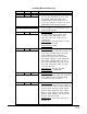
3.8.2 NEW CHART PRINTING REQUIREMENTS The following ACTION ON NEW CHART options are provided: NONE - JUST CONTINUE PRINT RANGE LIST PRINT SCALES The following example illustrates the format used if PRINT RANGE LIST has been configured. This method would be selected to reduce the time between chart installation and initial trend recording. This Range List corresponds to the example found at the end of this section.
The value recorded on Pen 2 is the temperature, zoned to record 20 to 120 on the lower 10% of the chart, and 120 to 210 on the upper 90% of the chart. The value recorded on Pen 3 is the pH, input 4 zoned to record 0 to 14 on the upper 70% of the chart. The value recorded on Pen 4 is the status of alarm A11, zoned to record 0 or 1 at 70% or 80% of the chart. Input 3, the pressure, is used in the derived value, but not recorded.
TABLE 3-2 Recorder Parameters (Not all parameters are shown) RECORDER NUMBER 1 2 3 4 Rs RECORDER TAG tttttttttttttttttttt FLOW #1 TEMP #1 PH #1 ALARM #1 Rs VALUE TO RECORD (VALUE) DV1 IV2 IV4 DV2 Rs PEN/COLOR (PEN/COLOR) BLUE GREEN BLACK RED RS CHART DIVISIONS nnn 100 100 100 100 Rs ZONE 1 LOW DIVISION n n n 0 0 30 70 Rs ZONE 1 HIGH DIVISION n n n 100 10 100 80 Rs SPAN 1 LOW nnnnnnn uuuuuu 0 GPM 20 F 0 PH 0 Rs SPAN 1 HIGH nnnnnnn uuuuuu 400 GPM 120 F 14 PH 1 Rs S
3.8.4 SEQUENCE OF EVENTS 11:27 PM 11:30 PM 11:31 PM 11:50 PM 12:20 PM 12:54 PM 1:12 PM Chart installed Instrument began printing with the Chart Tag, (UNIT #1) and the trend data collected and saved between 11:27 and 11:30, while continuing to save scanned data. Note the "¨" on the outer ring to indicate where trending began Instrument caught up to the current time and began normal trending. Flow rate went into alarm. Flow rate came out of alarm. Recording interrupted by power failure.
3.9 GETTING STARTED Before attempting any configuration/programming, review Sections 3.3 Keypad Function; 3.4 Changing Parameter Settings; 3.7 Display Details; 3.8 Chart Details; and Appendix C Reference Section.
3.10 QUICK START PROCEDURE This procedure can be used for starting up the recorder at the very basic level of recording inputs or to quickly familiarize yourself with the basic configuration process. A large number of default parameters are utilized and the default conditions are assumed. Please refer to the balance of Section 4 for important details on how to get full use of the instruments capabilities.
Step 8 Next, the display will show IVx DECIMAL POSITION, IVx RANGE LIMIT LOW, and IVx RANGE LIMIT HIGH. These will be used to calculate the engineering units range for volt/milliamp inputs for the Input being configured. For Thermocouple/RTD inputs, their values establish the expected range outside of which the instrument will consider the value "out of range". Select accordingly with the MOD, SCROLL, UP/DOWN arrows and ENTER.
Software Reference/Record Sheet Configuration INPUT Parameter DISPLAY TAG INPUT TYPE/RANGE T/C TYPE RTD TYPE DEG C/F SENSOR BREAK INPUT RANGE LOW INPUT RANGE HIGH PULSE RATE HIGH COMMS ADDRESS COMMS REGISTER REGISTER TYPE V/MA CONVERSION DISPLAY UNITS OTHER UNITS DECIMAL POSITION RANGE LIMIT LOW RANGE LIMIT HIGH EXPONENT CUTOFF TYPE CUTOFF VALUE INPUT CORRECT 1 INPUT CORRECT 2 VALUE FILTER DISPLAY OPTION OPEN/1 DESCR. CLOSED/0 DESCR.
Software Reference/Record Sheet Configuration INPUT Parameter DISPLAY TAG INPUT TYPE/RANGE T/C TYPE T/C INPUT SPAN RTD TYPE DEG C/F V/MA INPUT TYPE SENSOR BREAK INPUT RANGE LOW INPUT RANGE HIGH PULSE RATE HIGH COMMS ADDRESS COMMS REGISTER REGISTER TYPE V/MA CONVERSION DISPLAY UNITS OTHER UNITS DECIMAL POSITION RANGE LIMIT LOW RANGE LIMIT HIGH EXPONENT CUTOFF TYPE CUTOFF VALUE INPUT CORRECT 1 INPUT CORRECT 2 VALUE FILTER DISPLAY OPTION HIGH STATE DES LOW STATE DES DISPLAY FILTER Section 3 Input 5 Wide In
Software Reference/Record Sheet Configuration CONSTANTS Parameter CV-1 CV-2 CV-3 CV-4 VALUE Parameter Parameter CV-7 CV-5 CV-8 CV-9 CV-6 CV-10 CV-11 CV-7 CV-12 CV-8 VALUE Parameter CV-9 CV-10 CV-11 CV-12 VALUE Edition 3 Rev G 3-18 Section 3
Software Reference/Record Sheet Configuration CUSTOM CURVES Parameter CC-1 CC-2 DECIMAL POSITION OF INPUT DECIMAL POSITION OF OUTPUT NUMBER OF POINTS POINT PAIR 01 POINT PAIR 02 POINT PAIR 03 POINT PAIR 04 POINT PAIR 05 POINT PAIR 06 POINT PAIR 07 POINT PAIR 08 POINT PAIR 09 POINT PAIR 10 POINT PAIR 11 POINT PAIR 12 POINT PAIR 13 POINT PAIR 14 POINT PAIR 15 POINT PAIR 16 POINT PAIR 17 POINT PAIR 18 POINT PAIR 19 POINT PAIR 20 POINT PAIR 21 Section 3 --> --> --> --> --> --> --> --> --> --> --> --> --> -
Software Reference/Record Sheet Configuration CUSTOM CURVES Parameter CC-3 CC-4 DECIMAL POSITION OF INPUT DECIMAL POSITION OF OUTPUT NUMBER OF POINTS POINT PAIR 01 POINT PAIR 02 POINT PAIR 03 POINT PAIR 04 POINT PAIR 05 POINT PAIR 06 POINT PAIR 07 POINT PAIR 08 POINT PAIR 09 POINT PAIR 10 POINT PAIR 11 POINT PAIR 12 POINT PAIR 13 POINT PAIR 14 POINT PAIR 15 POINT PAIR 16 POINT PAIR 17 POINT PAIR 18 POINT PAIR 19 POINT PAIR 20 POINT PAIR 21 Edition 3 Rev G --> --> --> --> --> --> --> --> --> --> --> -->
Software Reference/Record Sheet Configuration DERIVED VARIABLES Parameter DISPLAY TAG FUNCTION INPUT 1 INPUT 2 INPUT 3 INPUT 4 INPUT 5 INPUT ACTUATOR RESET ACTUATOR DISPLAY UNITS UNITS DESCRIPTION DECIMAL POSITION VALUE FILTER DISPLAY OPTION DISPLAY FILTER Parameter DISPLAY TAG FUNCTION INPUT 1 INPUT 2 INPUT 3 INPUT 4 INPUT 5 INPUT ACTUATOR RESET ACTUATOR DISPLAY UNITS UNITS DESCRIPTION DECIMAL POSITION VALUE FILTER DISPLAY OPTION DISPLAY FILTER Section 3 DV-1 DV-2 DV-3 DV-4 seconds seconds seconds
Software Reference/Record Sheet Configuration DERIVED VARIABLES Parameter DISPLAY TAG FUNCTION INPUT 1 INPUT 2 INPUT 3 INPUT 4 INPUT 5 INPUT ACTUATOR RESET ACTUATOR DISPLAY UNITS UNITS DESCRIPTION DECIMAL POSITION VALUE FILTER DISPLAY VALUE DISPLAY FILTER Edition 3 Rev G DV-9 DV-10 DV-11 DV-12 seconds seconds seconds seconds seconds seconds seconds seconds 3-22 Section 3
Software Reference/Record Sheet Configuration PROCESS VARIABLES Parameter DISPLAY TAG INPUT DISPLAY UNITS OTHER UNITS DECIMAL POSITION VALUE FILTER DISPLAY OPTION DISPLAY FILTER Ax1 ALARM TYPE Ax1 TIME BASE Ax1 SAMPLE PERIOD Ax1 HYSTERESIS Ax2 ALARM TYPE Ax2 TIME BASE Ax2 SAMPLE PERIOD Ax2 HYSTERESIS Ax3 ALARM TYPE Ax3 TIME BASE Ax3 SAMPLE PERIOD Ax3 HYSTERESIS Ax4 ALARM TYPE Ax4 TIME BASE Ax4 SAMPLE PERIOD Ax4 HYSTERESIS LOOP ALARM TIME ALARM INHIBIT Section 3 PV-1 PV-2 PV-3 PV-4 seconds seconds se
Software Reference/Record Sheet Configuration CONTROLLERS Parameter CONTROLLER-1 CONTROL TYPE OUT 1 TYPE OUT 2 TYPE OUT 1 HYST OUT 2 HYST OUT 1 % LIMIT OUT 2 % LIMIT OUT 1 % ERROR OUT 2 % ERROR OUT SLEW RATE MANUAL ACTUATOR AUTO TRANSFER OFF MAIN SP SOURCE REMOTE SP ACTUATOR REMOTE SP SOURCE 2nd SP ACTUATOR 2nd SP SOURCE REMOTE SP RATIO REMOTE SP BIAS FEED FWD SOURCE FEED FWD HIGH FEED FWD LOW DISP SELECT SP DISP RAMPED SP DISP % OUTPUTS Edition 3 Rev G CONTROLLER-2 CONTROLLER-3 CONTROLLER-4 % % % %
Software Reference/Record Sheet Configuration CONTROL SETPOINTS Parameter Setpoint 1 Setpoint 2 Setpoint 3 Setpoint 4 Setpoint 1 Setpoint 2 Setpoint 3 Setpoint 4 *PROMPT TEXT DISPLAY UNITS OTHER UNITS DEC POSITION UPPER LIMIT LOWER LIMIT DISP OPTION Parameter *PROMPT TEXT DISPLAY UNITS OTHER UNITS DEC POSITION UPPER LIMIT LOWER LIMIT DISP OPTION * If the prompt text is blank, the setpoint is disabled and the remaining prompts will not be seen.
Software Reference/Record Sheet Configuration RECORDERS Parameter RECORDER TAG VALUE TO RECORD PEN/COLOR RECORDING METHOD DECIMAL POSITION CHART DIVISIONS ZONE 1 LOW ZONE 1 HIGH SPAN 1 LOW SPAN 1 HIGH SCALE 1 INTERVAL ZONE 2 HIGH SPAN 2 HIGH SCALE 2 INTERVAL POSIT ON ERROR FILTER Edition 3 Rev G RCDR-1 division division RCDR-2 division division division division divisions division divisions seconds division division division division division seconds 3-26 divisions divisions divisions divisio
Software Reference/Record Sheet Configuration TOTALIZERS Parameter DISPLAY TAG INPUT VALUE TIME BASE TOTAL IS FLOW DISPLAY UNITS DECIMAL POSITION DISPLAY OPTION DISPLAY FORMAT TOTALIZER TYPE TOTALIZER PRESET LOW FLOW CUTOFF RESET ACTUATOR HOLD ACTUATOR PULSED OUT PULSE EVERY Section 3 TOTAL-1 times no TOTAL-2 times yes no 3-27 TOTAL-3 times yes no TOTAL-4 times yes no yes Edition 3 Rev G
Software Reference/Record Sheet Configuration TIMERS Parameter TIME-1 TIME-2 TIME-3 TIME-4 DISPLAY TAG TIMER TYPE TIME FORMAT TIMER PERIOD RESET ACTUATOR DISPLAY OPTION Configuration LEDS Parameter LED-1 LED-2 LED-3 LED-4 LED-5 LED-6 LED-7 LED-8 ACTUATOR Parameter ACTUATOR Edition 3 Rev G 3-28 Section 3
Software Reference/Record Sheet Configuration RELAYS Parameter RELAY USAGE ACTUATOR T.P. VALUE CYCLE TIME Parameter RELAY USAGE ACTUATOR T.P.
Software Reference/Record Sheet Configuration CURRENT OUTPUTS Parameter SOURCE RANGE LOW RANGE HIGH OUTPUT RANGE OUTPUT ON ERROR Edition 3 Rev G CO-1 CO-2 CO-3 mA mA mA mA 3-30 CO-4 mA mA mA mA Section 3
Software Reference/Record Sheet Configuration INSTRUMENT SETTINGS Parameter INSTRUMENT TAG DISPLAY OPTION INSTR.
Software Reference/Record Sheet Configuration DERIVED ACTUATORS Derived Actuator Equation DA-1 DA-2 DA-3 DA-4 DA-5 DA-6 DA-7 DA-8 DA-9 DA-10 DA-11 DA-12 DA-13 DA-14 DA-15 DA-16 DA-17 DA-18 DA-19 DA-20 DA-21 DA-22 DA-23 DA-24 Edition 3 Rev G 3-32 Section 3
Software Reference/Record Sheet Configuration OPERATOR INPUTS Parameter PROMPT TEXT OFF/NO/0 CHOICE ON/YES/1 CHOICE ACTUATION STYLE POWER UP STATE WHEN DISPLAYED Parameter PROMPT TEXT OFF/NO/0 CHOICE ON/YES/1 CHOICE ACTUATION STYLE POWER UP STATE WHEN DISPLAYED Parameter PROMPT TEXT OFF/NO/0 CHOICE ON/YES/1 CHOICE ACTUATION STYLE POWER UP STATE WHEN DISPLAYED Parameter PROMPT TEXT OFF/NO/0 CHOICE ON/YES/1 CHOICE ACTUATION STYLE POWER UP STATE WHEN DISPLAYED Section 3 OI-01 OI-02 OI-03 Continuous Moment
Software Reference/Record Sheet Configuration OPERATOR MESSAGES Parameter OM-01 OM-02 OM-03 OM-04 OM-05 OM-06 OM-07 OM-08 OM-09 OM-10 OM-11 OM-12 ACTUATOR LINE 1 TEXT LINE 2 TEXT DISPLAY MODE Parameter ACTUATOR LINE 1 TEXT LINE 2 TEXT DISPLAY MODE Parameter ACTUATOR LINE 1 TEXT LINE 2 TEXT DISPLAY MODE Parameter ACTUATOR LINE 1 TEXT LINE 2 TEXT DISPLAY MODE Edition 3 Rev G 3-34 Section 3
Software Reference/Record Sheet Configuration CHART MESSAGES Parameter ACTUATOR PEN/COLOR MESSAGE TEXT VALUE 1 VALUE 2 VALUE 3 VALUE 4 TIME/DATE STAMP ORIENTATION Parameter ACTUATOR PEN/COLOR MESSAGE TEXT VALUE 1 VALUE 2 VALUE 3 VALUE 4 TIME/DATE STAMP ORIENTATION Parameter ACTUATOR PEN/COLOR MESSAGE TEXT VALUE 1 VALUE 2 VALUE 3 VALUE 4 TIME/DATE STAMP ORIENTATION Section 3 CM-01 CM-02 CM-03 No Yes No Yes No Yes CM-05 CM-06 CM-07 No Yes No Yes No Yes CM-09 CM-10 CM-11 No Yes No Yes No Yes
Software Reference/Record Sheet Configuration CONTROL STATE ACCESS Parameter Text CA1 LINE 1 TEXT CA1 LINE 2 TEXT CA1 F1 KEY USAGE CA1 F1 LINE 1 TEXT CA1 F1 OFF STATE TEXT CA1 F1 ON STATE TEXT CA1 F2 KEY USAGE CA1 F2 LINE 1 TEXT CA1 F2 OFF STATE TEXT CA1 F2 ON STATE TEXT CA1 F3 KEY USAGE CA1 F3 LINE 1 TEXT CA1 F3 OFF STATE TEXT CA1 F3 ON STATE TEXT CA1 F4 KEY USAGE CA1 F4 LINE 1 TEXT CA1 F4 OFF STATE TEXT CA1 F4 ON STATE TEXT CA1 F5 KEY USAGE CA1 F5 LINE 1 TEXT CA1 F5 OFF STATE TEXT CA1 F5 ON STATE TEXT
Software Reference/Record Sheet Configuration CONTROL STATE ACCESS Parameter Text CA2 LINE 1 TEXT CA2 LINE 2 TEXT CA2 F1 KEY USAGE CA2 F1 LINE 1 TEXT CA2 F1 OFF STATE TEXT CA2 F1 ON STATE TEXT CA2 F2 KEY USAGE CA2 F2 LINE 1 TEXT CA2 F2 OFF STATE TEXT CA2 F2 ON STATE TEXT CA2 F3 KEY USAGE CA2 F3 LINE 1 TEXT CA2 F3 OFF STATE TEXT CA2 F3 ON STATE TEXT CA2 F4 KEY USAGE CA2 F4 LINE 1 TEXT CA2 F4 OFF STATE TEXT CA2 F4 ON STATE TEXT CA2 F5 KEY USAGE CA2 F5 LINE 1 TEXT CA2 F5 OFF STATE TEXT CA2 F5 ON STATE TEXT
Software Reference/Record Sheet Configuration CONTROL STATE ACCESS Parameter Text CA3 LINE 1 TEXT CA3 LINE 2 TEXT CA3 F1 KEY USAGE CA3 F1 LINE 1 TEXT CA3 F1 OFF STATE TEXT CA3 F1 ON STATE TEXT CA3 F2 KEY USAGE CA3 F2 LINE 1 TEXT CA3 F2 OFF STATE TEXT CA3 F2 ON STATE TEXT CA3 F3 KEY USAGE CA3 F3 LINE 1 TEXT CA3 F3 OFF STATE TEXT CA3 F3 ON STATE TEXT CA3 F4 KEY USAGE CA3 F4 LINE 1 TEXT CA3 F4 OFF STATE TEXT CA3 F4 ON STATE TEXT CA3 F5 KEY USAGE CA3 F5 LINE 1 TEXT CA3 F5 OFF STATE TEXT CA3 F5 ON STATE TEXT
Software Reference/Record Sheet Configuration CONTROL STATE ACCESS Parameter Text CA4 LINE 1 TEXT CA4 LINE 2 TEXT CA4 F1 KEY USAGE CA4 F1 LINE 1 TEXT CA4 F1 OFF STATE TEXT CA4 F1 ON STATE TEXT CA4 F2 KEY USAGE CA4 F2 LINE 1 TEXT CA4 F2 OFF STATE TEXT CA4 F2 ON STATE TEXT CA4 F3 KEY USAGE CA4 F3 LINE 1 TEXT CA4 F3 OFF STATE TEXT CA4 F3 ON STATE TEXT CA4 F4 KEY USAGE CA4 F4 LINE 1 TEXT CA4 F4 OFF STATE TEXT CA4 F4 ON STATE TEXT CA4 F5 KEY USAGE CA4 F5 LINE 1 TEXT CA4 F5 OFF STATE TEXT CA4 F5 ON STATE TEXT
Software Reference/Record Sheet Configuration SIMULATED VARIABLES Parameter DISPLAY TAG TYPE DISPLAY UNITS OTHER UNITS DECIMAL POSITION RANGE LOW RANGE HIGH PERIOD (1/FREQ.
Software Reference/Record Sheet Configuration CHART PROGRAMMING Select Chart Configuration CHART SIZE CHART TYPE USED CHART TAG NORMAL SPEED MAJOR TIME PERIODS MINOR TIME PERIODS BLANK MAJOR PERIODS ALTERNATE SPEED USED ALT SPEED ACTUATOR ALTERNATE SPEED MAJOR TIME PERIODS MINOR TIME PERIODS BLANK MAJOR PERIODS MAJOR LINE PEN/COLOR MAJOR LINE PEN/COLOR (IF SELECT) MINOR LINE PEN/COLOR MINOR LINE PEN/COLOR (IF SELECT) TIME PEN/COLOR DATE/PEN COLOR CHART TAG PEN/COLOR ACTION ON NEW CHART STOP AFTER 1 REVOLUT
Software Reference/Record Sheet Configuration DISPLAY PROGRAMMING Parameter SEQUENTIAL DISPLAY DISPLAY MODE DISPLAY FORMAT Edition 3 Rev G DURATION _______ SECONDS CONTINUOUS SEQUENCE 1 VAL 2 VALS 4 VALS 3-42 Section 3
Software Reference/Record Sheet Configuration ALARM SETTINGS PV 1 ALM 1 (A11) ALM 2 (A12) ALM 2 ALM 1 (A21) ALM 3 ALM 2 (A22) ALM 4 ALM 3 ALM 4 ALM 3 (A13) ALM 4 (A14) ALM 3 (A23) ALM 4 (A24) ALM 3 (A33) ALM 4 (A34) ALM 3 (A43) ALM 4 (A44) SETPOINT PV 2 PV 2 ALM 1 SETPOINT PV 3 ALM 1 PV 3 SETPOINT PV 4 PV 4 ALM 2 ALM 1 (A31) ALM 1 ALM 2 ALM 1 (A41) ALM 2 (A32) ALM 3 ALM 2 (A42) ALM 4 SETPOINT Section 3 3-43 Edition 3 Rev G
Software Reference/Record Sheet Configuration ACTION TIME SETTINGS Parameter TIME 1 TAG TIME 1 DATE 1 TIME 2 TAG TIME 2 DATE 2 DAY OF WEEK ACTUATOR DAY OF MONTH ACTUATOR TIME DISPLAY OPTION Edition 3 Rev G 3-44 Section 3
Software Reference/Record Sheet Configuration TUNING PARAMETERS Parameter SP RAMP RATE OUT 1 P. BAND OUT 2 P.
Software Reference/Record Sheet Configuration ENABLES & PASSWORDS Circle your selected choice Factory setting is underlined Parameter ACTION TIME SETTINGS ALARM SETTINGS TUNING PARAMETERS SET POINT CHANGES CONFIGURATION DERIVED ACTUATORS OPERATOR INPUTS CONF OPERATOR MESSAGES CHART MESSAGES SIMULATED VARIABLES TEST CALIBRATION CHART PROMPTS CHART CONFIGURATION DISPLAY PROMPTS OPERATOR INPUTS CONTROL STATE ACCESS SYSTEM PROMPTS PASSWORD ENABLES & PASSWORDS PASSWORD CHART PROMPTS PASSWORD DISPLAY PROMPTS PAS
Section 4 - Configuration Selections made in Configuration set up the recorder for operation. Not all sections are applicable for every recorder. Before or during configuration of your recorder, it is recommended that the Software Reference/Record Sheet (found at end of Section 3) be completely filled in. 4.1 ENTERING CONFIGURATION From the Normal Display, press the until CONFIGURATION is seen in the lower display line.
2. Press the to advance to the next parameter, COPY/INITIALIZE. I N P U T S IVx COPY / INITIALIZE NO Press the Selections YES or NO to change, then to desired selection, then press or . Choose YES if the parameters to be programmed are the same as another INPUT already programmed. If selection is NO, see Step 3. If selection is YES: IVx COPY FROM INPUT (0 = INITIALIZED) Press the o r X Input to be copied from 0=FACTORY DEFAULT to change to the input number to be copied from. 3.
4. Press the to advance to the next parameter, INPUT TYPE/RANGE. IVx INPUT TYPE / RANGE OFF - NO INPUT Press the Selections OFF-NO INPUT TC NARROW TC WIDE RTD mA 25mV 100mV 1 VOLT 10 VOLT SWITCH CONTACT COMMS 5. Press the to change, then , to desired choice, then press the . to advance to the next parameter: OFF-NO INPUT selected, no other prompts for Input x will be seen, go to Step 1, Pg. 4-1. TC TYPE selected, go to Step 5A.
5B. IVx RTD TYPE I N P U T S PT 100 .00385 DIN Selections PT 100 .00385 DIN PT 100 .00392 USA PT 100 .00392 SAMA NI 100 Press the Press the to change, then to desired choice, then press the , . to advance to step 5C. 5C. If TC or RTD was selected, then press the to advance to the next parameter, DEGREES C/F. IVx DEGREES C / F °F Selections °C, °F Press the to change, then to desired choice, then the or , or press the Special key directly below the desired choice.
6. Press the to advance to the next parameter, SENSOR BREAK . IVx SENSOR BREAK I N P U T S UPSCALE Press the Selections UPSCALE DOWNSCALE Press the to change, then to desired choice, then press the . to advance through the next six prompts. They are six jumper position prompts, non-changeable, and are displayed for information /verification only. The jumper positions are based upon whether the input number is odd/even, input type, and span. Refer to Section 2.3.2 through 2.3.6.
8. If INPUT TYPE/RANGE selected was mA, mV, or VOLT, press the to advance to the next parameter, INPUT RANGE HIGH. I N P U T S Units correspond to units configured in INPUT TYPE/RANGE, mA, mV or VOLT. IVx INPUT RANGE HIGH 100.000 units Press the to change, then , then press or Selections ± 999 , then . 9. If INPUT TYPE/RANGE selected was PULSE, press the to advance to the next parameter, PULSE RATE HIGH.
11. If INPUT TYPE/RANGE selected was COMMS, press the to advance to the next parameter, COMMS REGISTER. IVx COMMS REGISTER I N P U T S 0 Press the to change, then , then press or Selections 0 to 65535 , then . 12. If INPUT TYPE/RANGE selected was COMMS, press the to advance to the next parameter, REGIS- TER TYPE. IVx REGISTER TYPE INT Press the INT Selections LONG FLOAT to change, then to desired choice, then press the 13. If INPUT TYPE/RANGE selected was mA, mV, or Volt, press the .
14. Press the to advance to the next parameter, DISPLAY UNITS. IVx DISPLAY UNITS I N P U T S °F Press the Selections °C °F OTHER to change, then to desired choice, then , or press the key directly below the desired choice. 15. If DISPLAY UNITS selected was OTHER, press the to advance to the next parameter, OTHER UNITS. IVx OTHER UNITS °F Refer to Section 3.4.2 Changing Text, page 3-3 for Selection Text 16. Press the instructions. to advance to the next parameter, DECIMAL POSITION.
17. If INPUT TYPE/RANGE selected was not SWITCH CONTACT, press the to advance to the next parameter, RANGE LIMIT LOW. IVx RANGE LIMIT LOW Units correspond to units configured in step 13 or 14. 0 units Press the to change, then desired value, or then press Selections ± 999999 (decimal position = 0) ± 9.9999 (decimal position = 4) to then , . 18. If INPUT TYPE/RANGE selected was not SWITCH CONTACT, press the to advance to the next parameter, RANGE LIMIT HIGH.
19. If V/mA conversion selected was EXP, press the to advance to the next parameter, EXPONENT. IVx EXPONENT I N P U T S 1.500 Press the Selections 0.000 to 5.000 20. Press the to change, then desired value, then press the to . to advance to the next parameter, CUTOFF TYPE. IVx VALUE CUTOFF TYPE NONE Selections NONE AT VALUE TO ZERO BELOW VALUE TO ZERO NEAR ZERO Press the to change, then , to desired choice, then press the . 21.
22. Press the to advance to the next parameter, INPUT CORRECT 1 (not seen if SWITCH CONTACT or COM was selected). IVx INPUT CORRECT 1 0 AT 0 Selections ± 999999 (decimal position = 0) ± 9.9999 (decimal position = 4) Press the the to change, I N P U T S Selections ± 999999 (decimal position = 0) ± 9.9999 (decimal position = 4) to select digit to change, then to desired digit, then press . This will change the correction (left number).
24. Press the to advance to the next parameter, VALUE FILTER. IVx VALUE FILTER I N P U T S 0 SECONDS Press the Selections 0 to 9999 seconds to change, then , then then press the 25. Press the or to desired value, . to advance to the next parameter, DISPLAY OPTION. IVx DISPLAY OPTION IN BOTH MODES Selections NOT DISPLAYED IN CONTINUOUS MODE IN SEQUENTIAL MODE IN BOTH MODES Edition 3 Rev G Press the to change, then desired choice, then press the 4-12 to .
26. If INPUT TYPE/RANGE selected was SWITCH CONTACT, press the to advance to the next param- eter, OPEN/1 DESCR.. IVx OPEN / 1 DESCR. OPEN Refer to Section 3.4.2 Changing Text, page 3-3 for Selections Text instructions. 27. If INPUT TYPE/RANGE selected was SWITCH CONTACT, press the to advance to the next param- eter, CLOSED/0 DESCR.. IVx CLOSED / 0 DESCR. CLOSED Selections Text Section 4 Refer to Section 3.4.2 Changing Text, page 3-3 for instructions.
28. Press the to advance to the next parameter, DISPLAY FILTER. IVx DISPLAY FILTER I N P U T S 0 SECONDS Press the Selections 0 to 9999 seconds , then & C O S T A N T S to change, then then press the 29. Press the section, page 4-1. or to desired value, . and the display advances to the next input to be programmed. Refer to the beginning of this 4.1.2 CONSTANTS Constants are available only when MATH has been specified and present in the model number order matrix.
2. Press the to advance to the next parameter, VALUE. CVx VALUE 1.00000 E 0 Press the to change, then desired position, then Selections -9.99999E37 to 9.99999E37 to to desired number, then press the . This will change the value (left number). Then change the exponent (right number) and then press . 3. Press the & and the display advances to the next constant to be programmed. Refer to the beginning of this section, page 4-14. 4.1.
1. Press the to display CUSTOM CURVE NUMBER. CUSTOM CURVE NUMBER C U S T O M C U R V E S 1 Press the to change, then desired number, then press the 2. Press the to Selections 1 to 4 . to advance to the next parameter, DECIMAL POSITION OF INPUT. CCx DECIMAL POSITION OF INPUT Press the to change, then desired number, then press the 3. Press the 0 to Selections 0 to 4 . to advance to the next parameter, DECIMAL POSITION OF OUTPUT.
4. Press the to advance to the next parameter, NUMBER OF POINTS. CCx NUMBER OF POINTS C U S T O M 2 Press the to change, then desired number, then press the 5. Press the to Selections 2 to 21 . to advance to the next parameter, POINT PAIR 01 . C U R V E S CCx POINT PAIR 01 0 --> 0 Selections ± 999999 (decimal position = 0) ± 9.9999 (decimal position = 4) Press the press the to change, then Selections ± 999999 (decimal position = 0) ± 9.
Repeat this step for each POINT PAIR prompt for mm equal to 03 through 21 (or less). 7. Press the D E R I V E D V A R I A B L E S and the display advances to the next custom curve to be programmed. Refer to the begin- ning of this section, page 4-15. 4.1.4 DERIVED VARIABLES Derived Variables utilize math to DERIVE a value from other variables and/or constants. Derived Variables are available only if MATH was specified and present in the model number order matrix.
2. Press the to advance to the next parameter, DISPLAY TAG. DVxx DISPLAY TAG DER VAL x Selections Character Selection Refer to Section 3.4.2 Changing Text, page 3-3 for instructions. 3. Press the to advance to the next parameter, FUNCTION. For FUNCTION descriptions, refer to the end of this section, Page 4-27.
4. Press the D E R I V E D V A R I A B L E S to advance to the next parameter, INPUT X. X = INPUT as required and specified by FUNCTION selection. DVxx INPUT X NONE USED Press the Selections NONE USED IV1 IV2 IV3 IV4 IV5 IV6 IV7 IV8 PV1 PV2 PV3 PV4 DV1 DV2 DV3 DV4 DV5 DV6 DV7 DV8 DV9 DV10 DV11 DV12 CV1 CV2 CV3 CV4 CV5 CV6 CV7 CV8 CV9 CV10 CV11 CV12 TOTAL1 TOTAL2 TOTAL3 TOTAL4 SV1 SV2 SV3 SV4 5. Press the to change, then or as required to pick desired choice, then press the .
6. Press the to advance to the next parameter, INPUT X, if it applies. DVxx INPUT X NONE USED Press the to change, then or Selections as required to pick desired choice, NONE USED IV1 IV2 IV3 IV4 IV5 IV6 IV7 IV8 PV1 PV2 PV3 PV4 DV1 DV2 DV3 then press the .
8. Press the to advance to the next parameter, INPUT X, if it applies. DVxx INPUT X D E R I V E D NONE USED Press the to change, then or Selections as required to pick desired choice, NONE USED IV1 IV2 IV3 IV4 IV5 IV6 IV7 IV8 PV1 PV2 PV3 PV4 DV1 DV2 DV3 then press the .
9. Press the to advance to the next parameter, INPUT ACTUATOR (Only seen if an actuator is required per the FUNCTION specified).
10. Press the to advance to the next parameter, RESET ACTUATOR, (Only seen if a reset actuator is required per the FUNCTION specified).
11. Press the to advance to the next parameter, DISPLAY UNITS. DVxx DISPLAY UNITS OTHER Press the Selections °C °F OTHER 12. Press the to change, then desired choice, then press the to . to advance to the next parameter, UNITS DESCRIP (only seen if OTHER was selected as DISPLAY UNITS) DVxx UNITS DESCRIP. Refer to Section 3.4.2 Changing Text, page 3-3 for instructions. Selections Text 13. Press the to advance to the next parameter, DECIMAL POSITION. DVxx DECIMAL POSIT.
14. Press the to advance to the next parameter, VALUE FILTER. DVxx VALUE FILTER D E R I V E D V A R I A B L E S 0 SECONDS Press the Selections 0 to 9999 seconds 15. Press the to change, then to pick desired value, then press the . to advance to the next parameter, DISPLAY OPTION. DVxx DISPLAY OPTION IN BOTH MODES Press the Selections NOT DISPLAYED IN CONTINUOUS MODE IN SEQUENTIAL MODE IN BOTH MODES 16. Press the to change, then to pick desired choice, then press the .
DERIVED VARIABLE FUNCTION To simplify formulas or make them easier to read, various letters or abbreviations are used for the inputs, such as A, B, X, or TEMP. During configuration, a descriptive prompt will appear on line 1, as specified by "PROMPT:" for each input, while the source of the input is selected via a choice of inputs on line 2. A Derived Variable can have up to five value inputs, one actuator input, and a reset actuator.
4. POLYNOMIAL INPUT 1: INPUT 2: INPUT 3: INPUT 4: INPUT 5: ACTUATOR: RESET: OUTPUT: 5. X PROMPT: A PROMPT: B PROMPT: C PROMPT: D PROMPT: n/a n/a = A*X**3 + B*X**2 + C*X + D DVxx INPUT X DVxx INPUT A DVxx INPUT B DVxx INPUT C DVxx INPUT D LINEAR MASS FLOW - AGA 3 LINEAER GAS FLOW INPUT 1: INPUT 2: INPUT 3: INPUT 4: INPUT 5: ACTUATOR: RESET: OUTPUT: F PROMPT: PRES PROMPT: TEMPF PROMPT: COMP PROMPT: C PROMPT: n/a n/a =C*F*SQRT (PRES/(TEMPR*COMP)) where: TMPR = TEMPF + 459.
NOTES: DP - Differential Pressure PRES - Static Pressure - must be ABSOLUTE TEMPF - Flow Temperature - must be degrees F COMP - Compressibility Correction C - Scaling Constant This function converts TEMP from degrees F to degrees R in the equation. 7. RELATIVE HUMIDITY INPUT 1: INPUT 2: INPUT 3: ACTUATOR: RESET: OUTPUT: DBT PROMPT: DVxx DRY BULB TEMP°F WBT PROMPT: DVxx WET BULB TEMP°F BARO PROMPT: DVxx BARO.
10. HIGH SELECT and LOW SELECT INPUT 1: INPUT 2: ACTUATOR: RESET: OUTPUT: 11. HIGH PEAK INPUT 1: ACTUATOR: RESET: OUTPUT: 12. YES PROMPT: DVxx ACTUATOR n/a = 0.0 if the state of the Selected Actuator is false = 1.0 if the state of the Selected Actuator is true. CONVERT F TO C INPUT 1: ACTUATOR: RESET: OUTPUT: Edition 3 Rev G A PROMPT: DVxx INPUT A B PROMPT: DVxx INPUT B YES PROMPT: DVxx SELECT B ACTUAT n/a = A if the state of the Selected Actuator is false.
17. CONVERT C TO F INPUT 1: ACTUATOR: RESET: OUTPUT: 18. A PROMPT: n/a n/a = (A * 9/5) +32 DVxx INPUT°C F PROMPT: TEMPH PROMPT: TEMPL PROMPT: C PROMPT: n/a n/a = C*F* (TEMPH-TEMPL) DVxx FLOW DVxx HIGHER TEMP DVxx LOWER TEMP DVxx SCALING CONST.
4.1.5 PROCESS VARIABLES Process Variables define variables for use with alarms and/or control outputs P R O C E S S V A R I A B L E S From the Normal Display, press the until CONFIGURATION is seen in the lower display line. If PASSWORD appears in the lower display line, the correct "password" will need to be entered before access to Configuration is allowed. If CONFIGURATION is not displayed, then Configuration has been disabled.
If selection is NO, proceed to step 3. If selection is YES: P R O C E S S PVx COPY FROM PV (0 = INITIALIZE) Press the X Process Variable to be copied from 0 = FACTORY DEFAULT to change to the process V A R I A B L E S variable to be copied from. 3. Press the to advance to the next parameter, DISPLAY TAG. PVx DISPLAY TAG PROCESS VAL Selections Text X Refer to Section 3.4.2 Changing Text, page 3-3 for instructions.
4. Press the to advance to the next parameter, INPUT TYPE. PVx INPUT P R O C E S S V A R I A B L E S NONE USED Press the Selections NONE USED IV1 IV2 IV3 IV4 IV5 IV6 IV7 IV8 PV1 PV2 PV3 PV4 DV1 DV2 DV3 DV4 DV5 DV6 DV7 DV8 DV9 DV10 DV11 DV12 CV1 CV2 CV3 CV4 CV5 CV6 CV7 CV8 CV9 CV10 CV11 CV12 TOTAL1 TOTAL2 TOTAL3 TOTAL4 SV1 SV2 SV3 SV4 to change, then , to desired choice, then press the .
6. If OTHER was selected in DISPLAY UNITS, press the to advance to the next parameter, OTHER UNITS. PVx OTHER UNITS °F Refer to Section 3.4.2 Changing Text, page 3-3 for Selections Text 7. Press the instructions. V A R I A B L E S to advance to the next parameter, DECIMAL POSITION. PV DECIMAL POSITION 0 Press the to change, then desired value, then press the 8. Press the to Selections 0 to 4 . to advance to the next parameter, VALUE FILTER.
9. Press the PVx DISPLAY OPTION P R O C E S S V A R I A B L E S to advance to the next parameter, DISPLAY OPTION. IN BOTH MODES Selections NOT DISPLAYED IN CONTINUOUS MODE IN SEQUENTIAL MODE IN BOTH MODES 10. Press the Press the to change, then to desired choice, then press the . to advance to the next parameter, DISPLAY FILTER. PVx DISPLAY FILTER 0 SECONDS Selections 0 to 9999 seconds Edition 3 Rev G Press the to change, then desired value, then press the 4-36 to .
11. Press the to advance to the next parameter, ALARM 1 TYPE. Ax1 ALARM TYPE OFF Selections for recorder only OFF PROCESS - HIGH Additional selections for use PROCESS - LOW with controller option RATE - RISING BAND - WITHIN RATE - FALLING BAND - OUTSIDE DEVIATION - ABOVE DEVIATION - BELOW CONTROL LOOP OPEN* P R O C E S S Note: Process Values must have been defined previously in order for ALARM prompts to appear. Press the to change, then to desired value, then press the .
12. Press the Ax1 TIME BASE P R O C E S S V A R I A B L E S to advance to the next parameter, ALARM 1 TIME BASE (only seen if Ax1 TYPE is RATE). PER SEC Selections PER SEC PER MIN PER HOUR PER DAY Press the , to desired choice, then press the 13. Press the to change, then . to advance to the next parameter, ALARM 1 SAMPLE PERIOD (only seen if Ax1 TYPE is RATE). Ax1 SAMPLE PERIOD 10 SECONDS Selections 1 to 9999 seconds 14.
15. Press the to advance to the next parameter, ALARM 2 TYPE. Ax2 ALARM TYPE OFF Selections for recorder only OFF PROCESS - HIGH Additional selections for use PROCESS - LOW with controller option RATE - RISING BAND - WITHIN RATE - FALLING BAND - OUTSIDE DEVIATION - ABOVE DEVIATION - BELOW CONTROL LOOP OPEN* Press the to change, then desired choice, then press the to .
17. Press the to advance to the next parameter, ALARM 2 SAMPLE PERIOD (only seen if Ax2 TYPE is RATE). Ax2 SAMPLE PERIOD P R O C E S S 10 SECONDS Press the Selections 1 to 9999 seconds 18. Press the V A R I A B L E S to change, then desired value, then press the to . to advance to the next parameter, ALARM 2 HYSTERESIS. Ax2 HYSTERESIS Note: Units correspond to units configured in Process Variables. 3 units Selections ± 999999 (decimal position = 0) ± 9.
20. Press the to advance to the next parameter, ALARM 3 TIME BASE (only seen if Ax3 TYPE is RATE). Ax3 TIME BASE P R O C E S S PER SEC Selections PER SEC PER MIN PER HOUR PER DAY Press the , to desired choice, then press the 21. Press the to change, then . to advance to the next parameter, ALARM 3 SAMPLE PERIOD (only seen if Ax3 TYPE is RATE). Ax3 SAMPLE PERIOD 10 SECONDS Selections 1 to 9999 seconds 22. Press the Press the to change, then desired value, then press the to .
23. Press the P R O C E S S V A R I A B L E S to advance to the next parameter, ALARM 4 TYPE. Ax4 ALARM TYPE OFF Selections for recorder only OFF PROCESS - HIGH Additional selections for use PROCESS - LOW with controller option RATE - RISING BAND - WITHIN RATE - FALLING BAND - OUTSIDE DEVIATION - ABOVE DEVIATION - BELOW CONTROL LOOP OPEN* Press the to change, then desired choice, then press the to .
25. Press the to advance to the next parameter, ALARM 4 SAMPLE PERIOD (only seen if Ax4 TYPE is RATE). Ax4 SAMPLE PERIOD 10 SECONDS Press the Selections 1 to 9999 seconds 26. Press the to change, then desired value, then press the to . V A R I A B L E S to advance to the next parameter, ALARM 4 HYSTERESIS. Ax4 HYSTERESIS Note: Units correspond to Units configured in Process Variables. 3 units Selections ± 999999 (decimal position = 0) ± 9.
27. Press the to advance to the next parameter, LOOP ALARM TIME (only seen if CONTROL LOOP OPEN selected as ALARM TYPE and ON/OFF selected as CONTROL TYPE). P R O C E S S PVx LOOP ALARM TIME 60 SECONDS Press the V A R I A B L E S to change, then to Selections 1 - 9999 desired number, then press the 28. Press the . to advance to the next parameter, ALARM INHIBIT (only seen if an Alarm has been configured).
4.1.6 RECORDERS Recorders defines values being recorded, tags, method, source of data and chart divisions and zoning. In the Normal Display, press the until CONFIGURATION is seen in the lower display line. If PASSWORD appears in the lower display line, the correct "password" will need to be entered before access to Configuration is allowed. If CONFIGURATION is not displayed, then Configuration has been disabled. Refer to Section 9, Enables and Passwords, for instructions to enable Configuration.
If selection was NO, proceed to step 3. If selection was YES: R E C O R D E R S Rs COPY FROM RECRDER (0 = INITIALIZE) Press the X to change to the recorder Recorder to be copied from 0 = FACTORY DEFAULT number to be copied from. 3. Press the to advance to the next parameter, RECORDER TAG. Rx RECORDER TAG Selections Text Refer to Section 3.4.2 Changing Text, page 3-3 for instructions.
4. Press the to advance to the next parameter, VALUE TO RECORD. Rx VALUE TO RECORD R E C O R D E R S NONE USED Press the Selections NONE USED IV1 IV2 IV3 IV4 IV5 IV6 IV7 IV8 PV1 PV2 PV3 PV4 DV1 DV2 DV3 DV4 DV5 DV6 DV7 DV8 DV9 DV10 DV11 DV12 CV1 CV2 CV3 CV4 CV5 CV6 CV7 CV8 CV9 CV10 CV11 CV12 TOTAL1 TOTAL2 TOTAL3 TOTAL4 SV1 SV2 SV3 SV4 to change, then , to desired choice, then press the .
6. Press the to advance to the next parameter, RECORDING METHOD. Rx RECORDING METHOD R E C O R D E R S DRAG - MIN TO MAX Press the Selections INSTANTANEOUS VALUES CONNECT THE VALUES DRAG - MIN TO MAX AVERAGE VALUES CONNECT THE AVERAGES 7. Press the to change, then desired choice, then press the to . to advance to the next parameter, DECIMAL POSITION. Rx DECIMAL POSITION 0 Press the to change, then to desired number, then press the 8. Press the Selections 0 to 4 .
9. Press the to advance to the next parameter, ZONE 1 LOW. Rx ZONE 1 LOW R E C O R D E R S DIVISION 0 Press the to change, then desired value, then press the 10. Press the Selections 0 to 200 to . to advance to the next parameter, ZONE 1 HIGH. Rx ZONE 1 HIGH DIVISION 100 Press the to change, then desired digit, then press the Section 4 Selections 0 to 200 to to desired value, then .
11. Press the to advance to the next parameter, SPAN 1 LOW. Rx SPAN 1 LOW R E C O R D E R S 0 units Press the to change, then desired number, then press the then to Selections ± 999999 (decimal position = 0) ± 9.9999 (decimal position = 4) . Units correspond to Units configured in corresponding Value to Record parameter, previously selected. 12. Press the to advance to the next parameter, SPAN 1 HIGH.
13. Press the to advance to the next parameter, SCALE 1 INTERVAL. Rx SCALE 1 INTERVAL R E C O R D E R S 10 DIVISIONS Press the to change, then desired number, then press the 14. Press the then to Selections 0 to 200 0 = NO SCALES . to advance to the next parameter, ZONE 2 HIGH. Rx ZONE 2 HIGH DIVISION 0 Press the to change, then desired number, then press the Section 4 Selections 0 to 200 0 = SINGLE ZONE to .
15. Press the to advance to the next parameter, SPAN 2 HIGH (Only if Zone 2 HIGH ≠ 0). Rx SPAN 2 HIGH R E C O R D E R S 0 units Press the to change, then desired number, then press the then to Selections ± 999999 (decimal position = 0) ± 9.9999 (decimal position = 4) . Units correspond to Units configured in corresponding Value to Record parameter, previously selected. 16. Press the to advance to the next parameter, SCALE 2 INTERVAL (Only if Zone 2 HIGH ≠ 0).
17. Press the to advance to the next parameter, POSITION ON ERROR (pen location in Chart Divisions on an ERROR condition). R E C O R D E R S Rx POSITION ON ERROR DIVISION Press the to change, then desired number, then press the 18. Press the 100 Selections 0 to 200 then to . to advance to the next parameter, FILTER. Rx FILTER 0 SECONDS Selections 0 to 9999 Press the to change, then desired value then press the 19. Press the to .
4.1.7 TOTALIZERS Totalizers are seen only if TOTALIZATION was specified and present in the model number order matrix. T O T A L I Z E R S From the Normal Display, press the until CONFIGURATION is seen in the lower display line. If PASSWORD appears in the lower display line, the correct "password" will need to be entered before access to Configuration is allowed. If CONFIGURATION is not displayed, then Configuration has been disabled.
If selection was NO, proceed to step 3. If selection was YES: T O T A L I Z E R S Tx COPY FROM TOTAL (0 = INITIALIZE) Press the X Totalizer to be copied from 0 = FACTORY DEFAULT to change to the totalizer number to be copied from. 3. Press the to advance to the next parameter, DISPLAY TAG. Tx DISPLAY TAG TOTAL X Refer to Section 3.4.2 Changing Text, page 3-3 for Selections Text Section 4 instructions.
4. Press the to advance to the next parameter, INPUT VALUE. Tx INPUT VALUE T O T A L I Z E R S NONE USED Press the Selections NONE USED IV1 IV2 IV3 IV4 IV5 IV6 IV7 IV8 PV1 PV2 PV3 PV4 DV1 DV2 DV3 DV4 DV5 DV6 DV7 DV8 DV9 DV10 DV11 DV12 CV1 CV2 CV3 CV4 CV5 CV6 CV7 CV8 CV9 CV10 CV11 CV12 TOTAL1 TOTAL2 TOTAL3 TOTAL4 SV1 SV2 SV3 SV4 to change, then , , as required to desired choice, then press the .
6. Press the to advance to the next parameter, TOTAL IS FLOW. Tx TOTAL IS FLOW TIMES Press the to change, then 7. Press the 1 to desired choice, then press the T O T A L I Z E R S Selections TIMES 1,000,000 TIMES 100,000 TIMES 10,000 TIMES 1,000 TIMES 100 TIMES 10 TIMES 1 TIMES 0.1 TIMES 0.01 TIMES 0.001 TIMES 0.0001 . to advance to the next parameter, DISPLAY OPTION. Tx DISPLAY UNITS GAL. Refer to Section 3.4.2 Changing Text, page 3-3 for Selections Text 8. Press the instructions.
9. Press the T O T A L I Z E R S to advance to the next parameter, DISPLAY OPTION. Tx DISPLAY OPTION IN BOTH MODES Selections NOT DISPLAYED IN CONTINUOUS MODE IN SEQUENTIAL MODE IN BOTH MODES 10. Press the Press the to change, then desired choice, then press the to . to advance to the next parameter, DISPLAY FORMAT. Tx DISPLAY FORMAT DIGITS - NO COMMAS Selections DIGITS - NO COMMAS DIGITS WITH COMMAS 11. Press the Press the to change, then desired choice, then press the to .
12. Press the to advance to the next parameter, TOTALIZER PRESET. Tx TOTALIZER PRESET -1 units Selections 0 to 999999999 (*decimal position = 0) 9999.9999 (*decimal position = 4) -1 = Off Press the to change, then desired value, then press the to . Note: Units are that of TOTAL. * Total Decimal Position 13. Press the to advance to the next parameter, LOW FLOW CUTOFF. Tx LOW FLOW CUTOFF 0 units Selections ± 999999 (*decimal position = 0) ± 9.
14. Press the T O T A L I Z E R S to advance to the next parameter, RESET ACTUATOR.
15. Press the to advance to the next parameter, HOLD ACTUATOR.
16. Press the T O T A L I Z E R S to advance to the next parameter, PULSED OUTPUT. Tx PULSED OUTPUT NO Selections NO YES 17. Press the Press the to change, then desired choice, then press the to . to advance to the next parameter, PULSE EVERY (only seen if PULSED OUTPUT select is YES). Tx PULSE EVERY 1000 units Selections 1 to 10000 Press the to change, then desired choice, then press the to . Note: Units are that of TOTAL. 18.
4.1.8 TIMERS Timers are seen only if the MATH option was specified and present in the model number order matrix. From the Normal Display, press the until CONFIGURATION is seen in the lower display line. If PASSWORD appears in the lower display line, the correct "password" will need to be entered before access to Configuration is allowed. If CONFIGURATION is not displayed, then Configuration has been disabled. Refer to Section 9, Enables and Passwords, for instructions to enable Configuration.
3. Press the to advance to the next parameter, TIMER TYPE. TMx TIMER TYPE T I M E R S OFF Press the Selections OFF COUNT UP COUNT DOWN to change, then , , as required to desired choice, then If OFF was selected, no other prompts for TIMER X press the . will be seen, refer back to step 1, page 4-61. 4. Press the to advance to the next parameter, TIME FORMAT.
6. Press the to advance to the next parameter, RESET ACTUATOR. TMx RESET ACTUATOR NONE / OFF Selections NONE/OFF Press the to change, then , ON/CONTINUOUS ANY ALARM , as required to desired choice, then ANY PROCESS ALARM A11 A12 A13 A14 A21 A22 A23 A24 A31 A32 A33 A34 A41 A42 A43 A44 press the .
7. Press the to advance to the next parameter, DISPLAY OPTION. TMx DISPLAY OPTION T I M E R S IN BOTH MODES Selections NOT DISPLAYED IN CONTINUOUS MODE IN SEQUENTIAL MODE IN BOTH MODES Press the to change, then desired choice, then press the to . & L E D S 8. Press the and the display advances to the next timer to be programmed. Refer to the beginning of this section, page 4-61. 4.1.
2. Press the to advance to the next parameter, LED ACTUATOR. LED x ACTUATOR NONE / OFF Selections NONE/OFF Press the to change, then , ON/CONTINUOUS ANY ALARM ANY PROCESS ALARM , as required to desired choice, then A11 A12 A13 A14 A21 A22 A23 A24 A31 A32 A33 A34 A41 A42 A43 A44 press the .
4.1.10 RELAYS Relays only available when specified and present in the model number order matrix. L E D S & R E L A Y S From the Normal Display, press the until CONFIGURATION is seen in the lower display line. If PASSWORDS appears in the lower display line, the correct "password" will need to be entered before access to Configuration is allowed. If CONFIGURATION is not displayed, then Configuruation has been disabled. Refer to SEction 9, Enables and Passwords, for instructions to enable Configuration.
3. Press the to advance to the next parameter, RELAY ACTUATOR (only available if RELAY USAGE selected was STATE OR ON-OFF or PULSED OUTPUT). RELAY x ACTUATOR NONE / OFF Selections NONE/OFF Press the to change, then , ON/CONTINUOUS ANY ALARM , as required to desired choice, then ANY PROCESS ALARM A11 A12 A13 A14 A21 A22 A23 A24 A31 A32 A33 A34 A41 A42 A43 A44 press the .
4. Press the to advance to the next parameter, RELAY T.P. VALUE (only seen if RELAY USAGE selected was TIME PROPORTIONING). R E L A Y S RELAY x T.P. VALUE NONE USED Press the Selections NONE USED IV1 IV2 IV3 IV4 IV5 IV6 IV7 IV8 PV1 PV2 PV3 PV4 DV1 DV2 DV3 DV4 DV5 DV6 DV7 DV8 DV9 DV10 DV11 DV12 CV1 CV2 CV3 CV4 CV5 CV6 CV7 CV8 CV9 CV10 CV11 CV12 TOTAL1 TOTAL2 TOTAL3 TOTAL4 SV1 SV2 SV3 SV4 5. Press the to change, then , , as required to desired choice, then press the .
4.1.11 CURRENT OUTPUTS Only seen if current outputs has been specified and present in the model number order matrix. From the Normal Display, press the until CONFIGURATION is seen in the lower display line. If PASSWORD appears in the lower display line, the correct "password" will need to be entered before access to Configuration is allowed. If CONFIGURATION is not displayed, then Configuration has been disabled. Refer to Section 9, Enables and Passwords, for instructions to enable Configuration.
3. Press the C U R R E N T O U T P U T S to advance to the next parameter, RANGE LOW. COx RANGE LOW Units correspond to Units configured in corresponding CO Source parameter previously selected. 0 units Press the Selections ± 999999 4. Press the desired value, then press the to . to advance to the next parameter, RANGE HIGH. COx RANGE HIGH Units correspond to Units configured in corresponding CO Source parameter previously selected. 100 units Press the Selections ± 999999 5.
6. Press the to advance to the next parameter, OUTPUT ON ERROR. COx OUTPUT ON ERROR 0 mA Selections 0 to 22 7. Press the Press the to change, then desired value, then press the to . and the display advances to the next current output to be programmed. Refer to the begin- ning of this section, page 4-69.
4.1.12 INSTRUMENT SETTINGS Instrument Settings define instrument tag, display option and date/time format. I N S T R U M E N T From the Normal Display, press the until CONFIGURATION is seen in the lower display line. If PASSWORD appears in the lower display line, the correct "password" will need to be entered before access to Configuration is allowed. If CONFIGURATION is not displayed, then Configuration has been disabled.
3. Press the to advance to the next parameter, INSTR. ON ACTUATOR. INSTR.
4. Press the I N S T R U M E N T to advance to the next parameter, ALARMING ON ACTUATOR.
5. Press the key to advance to the next parameter, CONTROL ON ACTUATOR (only seen on controller).
6. Press the DATE DISPLAY FORMAT I N S T R U M E N T S E T T I N G S to advance to the next parameter, DATE DISPLAY FORMAT. MM / DD / YY Press the to change, then Selections MM/DD/YY DD/MM/YY DD/MMM/YY as required to desired choice, then press the 7. Press the , . to advance to the next parameter, TIME DISPLAY FORMAT. TIME DISPLAY FORMAT AM / PM Press the Selections AM/PM 24 HOUR 8. Press the to change, then desired choice, then press the . to advance to the next parameter, CURRENT DATE.
9. Press the to advance to the next parameter, CURRENT DAY. CURRENT DAY Selections SUN MON TUE WED THUR FRI SAT 10. Press the Press the I N S T R U M E N T to change, then to desired choice, then press the . to advance to the next parameter, CURRENT TIME. CURRENT TIME format Press the to change, then 9:00 AM , S E T T I N G S Format: AM/PM 24 HOUR Enter Current Time as required to desired choice, then press the 11. Press the . Change and enter each portion of the date.
12. Press the to advance to the next parameter, COMMUNICATIONS MODE (Only seen if the communi- cations option is present). I N S T R U M E N T S E T T I N G S COMMUNICATIONS MODE SLAVE Selections SLAVE MASTER* Press the OFF to change, then desired choice, then press the to . * NOTE: When Master is selected, the recorder uses the comms address that was previously programmed. No slave unit should use this address.
15. Press the to advance to the next parameter, COMMS PARITY. COMMS PARITY ODD NONE 16. Press the Selections ODD EVEN Press the to change, then to desired choice, then press the I N S T R .
17. Press the and the display advances to INSTRUMENT TAG. To exit, press the . Refer to the beginning of this section, page 4-72. 4.1.13 DERIVED ACTUATORS Derived Actuators are used when two or more actuators need to be combined logically. From the Normal Display, press the until CONFIGURATION is seen in the lower display line. If PASSWORD appears in the lower display line, the correct "password" will need to be entered before access to Configuration is allowed.
2. Press the to advance to the next parameter, COPY/INITIALIZE. DAxx COPY / INITIALIZE NO Selections NO YES Press the to change, then desired choice, then press the to . A C T U A T O R S Choose YES if the parameters to be programmed are the same as another DERIVED ACTUATOR already programmed. If selection was NO, proceed to step 3.
3. Press the D E R I V E D to advance to the next parameter, ITEM 1.
4. Press the and the display advances to the next derived actuator to be programmed. Refer to the beginning of this section, page 4-80. 4.1.14 OPERATOR INPUTS Operator Inputs are prompts programmed that allow these prompts to turn on or off actuators that control some other function within the instrument. From the Normal Display, press the until CONFIGURATION is seen in the lower display line.
Choose YES if the parameters to be programmed are the same as another OPERATOR INPUT already programmed. D E R I V E D A C T U A T O R S If selection was NO, proceed to step 3. If selection was YES: OIxx COPY FROM OI (0 = INITIALIZE) Press the Operator Input to be copied from 0 = FACTORY DEFAULT to change to the desired actuator to be copied from. 3. Press the & O P E R A T O R 1 to advance to the next parameter, PROMPT TEXT. OIxx PROMPT TEXT Refer to Section 3.4.
4. Press the to advance to the next parameter, OFF STATE TEXT. OIxx OFF STATE TEXT OFF Refer to Section 3.4.2 Changing Text, page 3-3 for instructions. Selections Character Selection 5. Press the I N P U T S to advance to the next parameter, ON STATE TEXT. OIxx ON STATE TEXT ON Refer to Section 3.4.2 Changing Text, page 3-3 for Selections Character Selection 6. Press the instructions. to advance to the next parameter, ACTUATION STYLE.
7. Press the to advance to the next parameter, POWER UP STATE. OIxx POWER UP STATE O P E R A T O R I N P U T S SAME Selections OFF ON SAME Press the to change, then desired choice, then press the 8. Press the to . to advance to the next parameter, WHEN DISPLAYED. OIxx WHEN DISPLAYED ALWAYS Selections ALWAYS, WHEN ENABLED 9. Press the Press the to change, then desired choice, then press the to . and the display advances to the next operator input to be programmed.
4.1.15 OPERATOR MESSAGES Operator Messages are user defined messages to advise or provide information, via the display, that selected actuators are active. From the Normal Display, press the until CONFIGURATION is seen in the lower display line. If PASSWORD appears in the lower display line, the correct "password" will need to be entered before access to Configurat allowed. If CONFIGURATION is not displayed, then Configuration has been disabled.
If selection was NO, proceed to step 3. O P E R A T O R If selection was YES: OMxx COPY FROM OM (0 = INITIALIZE) Press the 1 to change to the desired Operator Message to be copied from 0 = FACTORY DEFAULT operator message to be copied from.
3. Press the to advance to the next parameter, ACTUATOR. O P E R A T O R OMxx ACTUATOR NONE / OFF Selections NONE/OFF Press the to change, then , ON/CONTINUOUS ANY ALARM as required to desired choice, then ANY PROCESS ALARM A11 A12 A13 A14 A21 A22 A23 A24 A31 A32 A33 A34 press the .
4. Press the OMxx LINE 1 TEXT O P E R A T O R M E S S A G E S to advance to the next parameter, LINE 1 TEXT. MESSAGE X Refer to Section 3.4.2 Changing Text, page 3-3 for Selections Character Selection 5. Press the instructions. to advance to the next parameter, LINE 2 TEXT. OMxx LINE 2 TEXT Refer to Section 3.4.2 Changing Text, page 3-3 for Selections Text 6. Press the instructions. to advance to the next parameter, DISPLAY MODE.
7. Press the and the display advances to the next operator message to be programmed. Refer to the beginning of this section, page 4-85. 4.1.16 CHART MESSAGES Chart Messages allow user defined text to be recorded on the chart. From the Normal Display, press the until CONFIGURATION is seen in the upper display line. If PASSWORD appears in the lower display line, the correct "password" will need to be entered before access to Configuration is allowed.
Choose YES if the parameters to be programmed are the same as another CHART MESSAGE already programmed. C H A R T M E S S A G E S If selection is NO, proceed to step 3. If selection is YES: CMxx COPY FROM CM (0 = INITIALIZE) Press the 1 to change to the desired chart Chart Message to be copied from 0 = FACTORY DEFAULT message to be copied from.
3. Press the to advance to the next parameter, ACTUATOR. CMxx ACTUATOR C H A R T NONE / OFF Selections NONE/OFF Press the to change, then , ON/CONTINUOUS ANY ALARM as required to desired choice, then ANY PROCESS ALARM A11 A12 A13 A14 A21 A22 A23 A24 A31 A32 A33 A34 A41 A42 A43 A44 press the .
4. Press the CMxx PEN / COLOR C H A R T M E S S A G E S to advance to the next parameter, PEN/COLOR. RED Press the Selections BLUE GREEN RED BLACK VIOLET to change, then desired choice, then press the to . Note: Valid choice of color depends on number of colors specified when ordered. One color - Red, Two colors Red, Green; Three colors - Red, Green, Blue or Four colors - Red, Green, Blue, Black or Violet. 5. Press the to advance to the next parameter, MESSAGE TEXT.
6. Press the to advance to the next parameter, VALUE 1. CMxx VALUE 1 NONE USED Press the to change, then , Selections as required to desired choice, then NONE USED IV1 IV2 IV3 IV4 IV5 IV6 IV7 IV8 PV1 PV2 PV3 PV4 DV1 DV2 DV3 press the .
8. Press the to advance to the next parameter, VALUE 3. CMxx VALUE 3 C H A R T NONE USED Press the to change, then , Selections as required to desired choice, then NONE USED IV1 IV2 IV3 IV4 IV5 IV6 IV7 IV8 PV1 PV2 PV3 PV4 press the .
10. Press the to advance to the next parameter, TIME/DATE STAMP. CMxx TIME / DATE STAMP C H A R T NO Press the Selections YES NO 11. Press the to change, then desired choice, then press the to . M E S S A G E S to advance to the next parameter, CMSS ORIENTATION. CMxx ORIENTATION HORIZONTAL Press the Selections HORIZONTAL VERTICAL to change, then desired choice, then press the to & . 12. Press the and the display advances to the next chart message to be programmed.
1. Press the S I M U L A T E D V A R I A B L E S to display SV NUMBER. SV NUMBER 1 Press the to change, then desired number, then press the 2. Press the to Selections 1 to 4 . to advance to the next parameter, DISPLAY TAG. SVx DISPLAY TAG SIM VAL X Selections Text Refer to Section 3.4.2 Changing Text, page 3-3 for instructions. 3. Press the to advance to the next parameter, TYPE. SVx TYPE OFF Press the to change, then to desired choice, then press the.
If OFF was selected, no other prompts for SIMULATED VARIABLES X will be seen. Refer back to step 1, page 4-97. 4. Press the S I M U L A T E D to advance to the next parameter, DISPLAY UNITS. SVx DISPLAY UNITS °F °C Selections °F OTHER 5. If DISPLAY UNITS selected was OTHER, press the to advance to the next parameter, OTHER UNITS. SVx OTHER UNITS Refer to Section 3.4.2 Changing Text, page 3-3 for Selections Text 6. Press the instructions. to advance to the next parameter, DECIMAL POSITION.
7. Press the S I M U L A T E D V A R I A B L E S to advance to the next parameter, RANGE LOW. SVx RANGE LOW 0 Press the units to change, then Selections ± 999999 (decimal position = 0) ± 9.9999 (decimal position = 4) to desired value, then press the . 8. Press the to advance to the next parameter, RANGE HIGH.
9. Press the to advance to the next parameter, PERIOD. SVx PERIOD (1 / FREQ.) S I M U L A T E D 60 MINUTES Selections 1 to 1440 10. Press the to advance to the next parameter, DISPLAY OPTION. V A R I A B L E S SVx DISPLAY OPTION IN BOTH MODES Selections NOT DISPLAYED IN CONTINUOUS MODE IN SEQUENTIAL MODE IN BOTH MODES 11. Press the and the display advances to the next simulated input to be pro- grammed. Refer to the beginning of this section, page 4-95.
Section 5 - Display Programming Selections made in the Display prompts section determine what is displayed and how it is displayed. From the Normal Display, press the . If the Display prompts are disabled, when the DISP key is pressed, DISPLAY KEY DISABLED will appear in the lower display line. Refer to Section 9, Enables and Passwords, for instructions to enable Display prompts.
3. When this prompt is displayed with the AUTOMATIC/MANUAL choice, if the associated controller is configured for PID control and is in the manual mode, pressing the DOWN key will display the prompts below: Note: The controller may have its manual actuator set to something other than CAxFn, and in this case the prompts below may be accessible even if the above section was AUTOMATIC.
To change the setpoint, press the key, then keys to desired setpoint, then press the key. To exit, press the key. 5. Following the top level Setpoint Prompt, if any controllers are configured for PID control and are in manual mode, the following prompt will appear: SELECT MANUAL VALUES This prompt provides an alternative method of manually changing controller outputs.
6. Following the top level Manual Values prompts, the "Standard Display" prompts are displayed as follows: DISPLAY MODE CONTINUOUS SEQUENCE AMM used, default CONTINUOUS DISPLAY FORMAT 1 VAL 2 VALS 4 VALS AMM used, default 1 VAL SEQUENTIAL DISPLAY DURATION n SECONDS SEQUENCE, AMM used, default 1 7. If any OPERATOR INPUTS (OIs) are configured and visible, they appear in numerical order following the above prompts.
Section 6 - Chart Prompts From the Normal Display, press the . If the Chart Prompts are disabled, when the CHART key is pressed, CHART KEY DISABLED will appear in the lower display. Refer to Section 9, Enables & Passwords, for instructions to enable Chart Prompts. If the Chart Prompts are not disabled BUT the password is other than zero, CHART PROMPTS PASSWORD will appear in the display when the CHART key is pressed. If the correct "password" is entered, CHANGE CHART will appear in the upper display.
6. Upon selection of YES, the chart is initialized and the unit exits to the NORMAL DISPLAY if Chart Rotation and Trend Data Collect are ON. If either Chart Rotation or Trend Data Collect are OFF, after the initialization message, the unit will display CHART ROTATION OFF and/or TREND DATA COLLECT OFF, as applicable, until any key is pressed. This is a reminder that normal recording will not commence. 6.
3. Press the to advance to the next parameter, CHART TAG. CHART TAG UNIT #1 Refer to Section 3.4.2 Changing Text, Page 3-3, for instructions. Selection Text 4. Press the to advance to the next parameter, NORMAL SPEED. NORMAL SPEED 24 HOUR Press the Selection 8 HOUR 12 HOUR 24 HOUR 48 HOUR 7 DAY OTHER , to desired choice, then press the 5. Press the to change, then . to advance to the next parameter, NORMAL SPEED (only seen if NORMAL SPEED selected was OTHER).
6. Press the to advance to the next parameter, MAJOR TIME PERIODS. MAJOR TIME PERIODS 24 Press the to change, then desired digit, then then press the 7. Press the to Selections 6 to 48 to desired value, . to advance to the next parameter, MINOR TIME PERIODS. MINOR TIME PERIODS 2 Press the to change, then desired value, then press the 8. Press the to Selections 0 to 8 . to advance to the next parameter, BLANK MAJOR PERIODS.
9. Press the to advance to the next parameter, MAJOR LINE PEN/COLOR. MAJOR LINE PEN / COLOR MATCH SCALE COLOR Selections MATCH SCALE COLOR SELECT A COLOR 10. Press the Press the to change, then desired choice, then press the to . to advance to the next parameter, MAJOR LINE PEN/COLOR (only seen if MAJOR LINE PEN/COLOR selected was SELECT A COLOR). MAJOR LINE PEN / COLOR Note: Valid choice of color depends on number of colors specified when ordered.
11. Press the to advance to the next parameter, MINOR LINE PEN/COLOR. MINOR LINE PEN / COLOR MATCH SCALE COLOR Selections MATCH SCALE COLOR SELECT A COLOR 12. Press the Press the to change, then desired choice, then press the to . to advance to the next parameter, MINOR LINE PEN/COLOR (only seen if MINOR LINE PEN/COLOR selected was SELECT A COLOR). MINOR LINE PEN / COLOR Note: Valid choice of color depends on number of colors specified when ordered.
13. Press the to advance to the next parameter, TIME PEN/COLOR. TIME PEN / COLOR RED Note: Valid choice of color depends on number of colors specified when ordered. One color Red; Two colors - Red, Green; Three colors Red, Green, Blue; or Four colors - Red, Green, Blue, Black or Violet. 14. Press the Press the Selections BLUE GREEN RED BLACK VIOLET to change, then desired choice, then press the to . to advance to the next parameter, DATE/PEN COLOR.
15. Press the to advance to the next parameter, CHART TAG PEN/ COLOR. CHART TAG PEN / COLOR RED Note: Valid choice of color depends on number of colors specified when ordered. One color Red; Two colors - Red, Green; Three colors Red, Green, Blue; or Four colors - Red, Green, Blue, Black or Violet. 16. Press the Selections BLUE GREEN RED BLACK VIOLET Press the to change, then desired choice, then press the to . to advance to the next parameter, ACTION ON NEW CHART.
18. Press the to advance to the next parameter, ROTATE CHART ACTUATR.
19. Press the to advance to the next parameter, COLLECT DATA ACTUATR.
20. Press the to advance to the next parameter, CHART ROTATION. CHART ROTATION PROMPT DISPLAYED Selections PROMPT NOT DISPLAYED PROMPT DISPLAYED 21. Press the Press the to change, then desired choice, then press the to . to advance to the next parameter, TREND DATA COLLECT. TREND DATA COLLECT PROMPT NOT DISPLAYED Press the Selections PROMPT NOT DISPLAYED PROMPT DISPLAYED 22. Press the to change, then desired choice, then press the to . to advance to the next parameter, CHART SPEED PROMPT.
Section 7 - Alarm Settings Selections made in Alarm Settings determine the setpoints (or RATE if RATE alarm selected) of each alarm configured in the Process Variables section of the Configuration section in System Prompts. From the Normal Display, press the until ALARM SETTINGS appears in the lower display line. If PASSWORD appears in the lower display line, the correct "password" will need to be entered before access to Alarm Settings is allowed.
3. Press the to advance to the next parameter, ALARM 2 SETPOINT. If RATE Alarm was selected, setpoint refers to RATE. Ax2 SETPOINT Units correspond to Units configured in Process Variables with per unit time included if a rate of change alarm is specified. 100 units Press the Selections ± 999999 • Decimal position configured in Process (*decimal position = 0) ± 9.9999 Variables. (*decimal position = 4) 4. Press the to change, then desired value, then press the to .
5. Press the to advance to the next parameter, ALARM 4 SETPOINT. If RATE Alarm was selected, setpoint refers to RATE. Ax4 SETPOINT Units correspond to Units configured in Process Variables with per unit time included if a rate of change alarm is specified. * Decimal position configured in Process Variables. 6. Press the 100 units Selections ± 999999 (*decimal position = 0) ± 9.9999 (*decimal position = 4) Press the to change, then desired value, then press the to .
Section 8 - Action Time Settings Action Time Settings are simply TIME/DATE settings that can be used to initiate a desired action. Selections made in Action Time Settings are used to generate actuators TIME 1, TIME/DATE 1, TIME 2, TIME/DATE 2, TIME 1 TO TIME 2, and TIME/DATE 1 TO 2. The TIME 1 and TIME 2 actuators are TRUE when the time is equal to or greater than the TIME values during each 24 hour day, and FALSE between midnight and the TIME specified.
2. Press the to advance to the next parameter, TIME 1. TIME 1 format 06:00 AM Press the FORMAT AND ENTRY PER TIME FORMAT SELECTED IN INSTRUMENT SETTINGS CONFIGURATION to change, then , to desired value, then press the . Change and enter each portion of the time. 3. Press the to advance to the next parameter, DATE 1.
4. Press the to advance to the next parameter, TIME 2 TAG. TIME 2 TAG STOP TIME Refer to Section 3.4.2 Changing Text, page 3-3 for Selections Text 5. Press the instructions. to advance to the next parameter, TIME 2. TIME 2 format FORMAT AND ENTRY PER TIME FORMAT SELECTED IN INSTRUMENT SETTINGS CONFIGURATION 06:00 AM Press the to change, then , to desired value, then press the . Change and enter each portion of the time.
6. Press the to advance to the next parameter, DATE 2. DATE 2 format XX / XX / XX Will read current date FORMAT AND ENTRY PER TIME FORMAT SELECTED IN INSTRUMENT SETTINGS CONFIGURATION Press the to change, then , to desired value, then press the . Change and enter each portion of the date. 7. Press the to advance to the next parameter, DAY OF WEEK ACTUATOR. DAY OF WEEK ACTUATOR SUN SUN MON TUE WED THUR FRI SAT Press the to change, then to desired value, then press the , .
8. Press the to advance to the next parameter, DAY OF OF MONTH ACTUATOR. DAY OF MONTH ACT. 1 Press the Selections 1 to 31 to change, then , to desired value, then press the . Day of Month Actuator works according to the days numerical date. For example, if today's date is the 15th and the DAY OF MONTH ACTUATOR date is selected is 15, the actuator will be active until the clock calendar rolls over to the 16th. 9. Press the to advance to the next parameter, TIME DISPLAY OPTION.
Section 9 - Enables & Passwords Enables and Passwords provides a means of enabling or disabling prompt sections and provides additional operational security with the use of 6 digit password. If the Display prompts or Chart prompts are disabled, those prompt sections will not be accessible and DISPLAY KEY DISABLED or CHART KEY DISABLED will be displayed when the corresponding key is pressed. If other prompt sections are disabled, their corresponding access or selection prompts will not appear.
2. Press the to advance to the next parameter, ACTION TIME SETTINGS. ACTION TIME SETTINGS Selections DISABLED ENABLED 3. Press the Press the to change, then desired choice, then press the , to . to advance to the next parameter, PROFILE ENTRY (Only on Profiles). PROFILE ENTRY (Only on Profilers) Selections DISABLED ENABLED Press the to change, then desired choice, then press the 4. Press the , to . to advance to the next parameter, PROFILE CONTROL (Only on Profiles).
. 5. Press the to advance to the next parameter, ALARM SETTINGS. ALARM SETTINGS Selections DISABLED ENABLED Press the to change, then desired choice, then press the 6. Press the , to . to advance to the next parameter, TUNING PARAMETERS (only seen if CONTROLLER). TUNING PARAMETERS Selections DISABLED ENABLED 7. Press the Press the to change, then desired choice, then press the , to . to advance to the next parameter, SETPOINT CHANGES (only seen if CONTROLLER).
8. Press the to advance to the next parameter, CONFIGURATION. CONFIGURATION Selections DISABLED ENABLED Press the to change, then desired choice, then press the 9. Press the , to . to advance to the next parameter, DERIVED ACTUATORS. DERIVED ACTUATORS Press the Selections DISABLED ENABLED 10. Press the to change, then desired choice, then press the , to . to advance to the next parameter, OPERATOR INPUTS CONFIGURATION.
11. Press the to advance to the next parameter, OPERATOR MESSAGES. OPERATOR MESSAGES Press the Selections DISABLED ENABLED 12. Press the to change, then , to desired choice, then press the . to advance to the next parameter, CHART MESSAGES. CHART MESSAGES Press the Selections DISABLED ENABLED 13. Press the to change, then desired choice, then press the , to . to advance to the next parameter, SIMULATED VARIABLES.
14. Press the to advance to the next parameter, TEST. TEST Selections DISABLED ENABLED 15. Press the Press the to change, then desired choice, then press the , to . to advance to the next parameter, CALIBRATION. CALIBRATION Selections DISABLED ENABLED 16. Press the Press the to change, then desired choice, then press the , to . to advance to the next parameter, CHART PROMPTS.
17. Press the to advance to the next parameter, CHART CONFIGURATION. CHART CONFIGURATION Press the Selections DISABLED ENABLED 18. Press the to change, then desired choice, then press the , to . to advance to the next parameter, DISPLAY PROMPTS. DISPLAY PROMPTS Selections DISABLED ENABLED 19. Press the Press the to change, then desired choice, then press the , to . to advance to the next parameter, OPERATOR INPUTS.
20. Press the to advance to the next parameter, CONTROL STATE ACCESS (only seen if CONTROL- LER) CONTROL STATE ACCESS Press the Selections DISABLED ENABLED 21. Press the to change, then , to desired choice, then press the . to advance to the next parameter, SYSTEM PROMPTS PASSWORD. SYSTEM PROMPTS PASSWORD REQ. Press the Selections 0 to 999999 (0=No password protection) 22. Press the 0 to change, then desired value, then press the , to .
23.Press the to advance to the next parameter, CHART PROMPTS PASSWORD. CHART PROMPTS PASSWORD Press the to change, then desired value, then press the 24. Press the 0 , to Selections 0 to 999999 (0=No password protection) . to advance to the next parameter, DISPLAY PROMPTS PASSWORD. DISPLAY PROMPTS PASSWORD Press the to change, then desired value, then press the 25. To exit, press the Section 9 0 , to Selections 0 to 999999 (0=No password protection) . .
Section 10 - Test Test describes all possible diagnostic tests built into the recorder. From the Normal Display, depress the until TESTS appears in the lower display line. If PASSWORD appears in the lower display line, the correct "password" will need to be entered before access to Test is allowed. If TESTS is not displayed, then Test has been disabled. Refer to Section 9, Enables and Passwords, for instructions to enable Test. A list of available tests and their purpose are shown in Table 10-1.
10.1 RELAY TEST Allows the operator to verify that the LEDs, Relay and/or SSRD output(s) is/are working. A Volt/Ohm meter will be required to test the output. Step 1 With RELAY in the lower display line, depress the and INITIATE RELAY TEST appears in the upper display line and NO appears in the lower display line. Depress , select YES, depress to perform the test. Step 2 TEST IN PROCESS appears in the upper display line, LED 1 will be lit and Relay 1 will be energized or SSRD 1 will be on.
10.3 KEYPAD TEST Allows the operator to verify that the keypad is functional. No test equipment is required to perform this test. Step 1 With KEYPAD in the lower display line, depress the and INITIATE KEYPAD TEST appears in the upper display line and NO appears in the lower display line. Depress , select YES, then depress to start the test. Step 2 THE KEY PRESSED WAS appears in the upper display line and ENTER KEY appears in the lower display line.
10.5 CHART DEMONSTRATION Allows the user to demonstrate the chart capabilites. CAUTION: When this "TEST" is intiated, any parameter values previously programmed will be replaced with the demonstration values. Step 1 With CHART DEMONSTRATION in the lower display line, depress the in the upper display line and NO appears in the lower display line.
Step 4 The current output reading should be equal to the displayed value. Step 5 To exit the test, depress the Section 10 and the instrument will return to the normal display.
Section 11 - Calibration Calibration describes all possible field calibration procedures for the recorder as well as methods of invoking default program and calibration values. The procedures described include the input and range calibration as well as chart calibration. From the Normal Display, press the until CALIBRATION appears in the lower display line. If PASSWORD appears in the lower display line, the correct "password" will need to be entered before access to Calibration is allowed.
11.1 INPUT CALIBRATION This routine allows for the calibration of all input channels and all input types. Important Notes: 1. The calibration information is stored on each input board for all input types in an Electrically Erasable Programmable Read Only Memory (EEPROM). The instrument and every input board supplied to the field is shipped from the factory calibrated for each input type. 2.
Step 4 Be sure that the jumpers on the Input Board for the Input being calibrated are positioned as shown in Table 11-3, and Figure 11-1 or Table 11-3A and Figure 11-1A, depending on which circuit board is fitted.
SIDE VIEW Board 4 Board 3 Board 2 Board 1 FOR INPUTS BOARD POSITION 1 1, 3, 5, 7 JU13 2, 4, 6, 8 JU14 2 3 4 When installing an Input Board for any reason, check the location (where this board is mounted), then verify the position of JU13 and/or JU14. TC WIDE or TC NARROW were selected, go to Step 5, if not, go to Step 6. Step 5 Depress the and the upper display line will show IVx CAL CJC OR TC and the lower display line will show TC, or CJC.
Step 8 Repeat steps 1 through 8 for each input to be calibrated. 11.2 COLD JUNCTION CALIBRATION Step 1 With INPUT CALIBRATION on the lower display line, press the to enter the Input Calibration. The upper display will display CALIBRATE INPUT and the lower display line will display IV1. If other than IV1 or IV2 is to be calibrated, depress and select the input number for which it is desired to calibrate. Note: There exists only one CJC sensor per input board or for every two input channels.
Step 7 Connect the proper TC type up to the input being calibrated. Place the thermometer next to the HOT Junction (sensor point) of the TC connected. Depress the and the upper display line will display IVx CAL CJC and lower display line will display CJC READS: 25.0 C. Depress the , then use the UP/DOWN to change the display to read what the mercury thermometer is reading, then depress the . Step 8 Depress the and the upper display line will display IVx PERFORM CAL.
CHART SCROLL UP DOWN RESET ESC ENTER Will place a dot on the inner or outer ring, whichever is selected for calibration Will select either the inner or outer ring Will move the selected (inner or outer) ring position to the left and print a dot in the new position without moving the chart. Will move the selected (inner or outer) ring position to the right and print a dot in the new position without moving the chart.
Step 2 Connect the milliamp meter across the corresponding output terminals observing proper polarity, terminal 1 is positive. Step 3 Depress and INITIATE mA CAL appears in the upper display line and NO appears in the lower display line. Depress select YES, then depress . Step 4 The display should be flashing the message: USE UP/DN TO ADJUST OUTPUT TO 20 mA ENTER WHEN DONE. Depress or and HIT UP/DN OR ENTER appears in the upper display line and OUTPUT TO 20 mA appears in the lower display line.
Step 1 With CALIBRATION DEFAULTS in the lower display line, depress the the upper display line and NO appears in the lower display line. Step 2 Depress Section 11 and then select YES, then depress . SET CAL DEFAULTS appears in .
SECTION 13 - CONTROLLERS When the instrument is specified with the Controller option, in addition to the normal configuring required for the Recorder functions, other parameters such as CONTROLLERS, SETPOINTS, and TUNING PARAMETERS will need to be configured in order for the instrument to operate properly. Along with the above, additional choices will appear in the selection list for certain prompts found elsewhere in this manual.
Up to 8 setpoints can be configured. Each has a variable text prompt, units, decimal position, limits, and “normal display” display option. Whenever the PROMPT TEXT, as configured in SETPOINTS, is not blank, the setpoint will be displayed in the key prompts. The setpoints are not inherently associated with a controller, so they can also be used for ratios, direct drive outs (to a current output), or any other purposes. Setpoint changes can be inhibited via the ENABLES and PASSWORDS.
To utilize the CONTROL STATE ACCESS capability and select either AUTOMATIC or MANUAL control, proceed as follows: From the “Normal Display”, depress the key, CONTROLLER 1 should be displayed on the upper display line (or what was configured for CA1 LINE 1 TEXT above) and A/M should be displayed on the lower display line (or what was configured for CA1 LINE 2 TEXT above). Depress the key directly below A/M and the lower display line should display AUTOMATIC MANUAL with the active selection blinking.
2. Press the to advance to the next parameter, COPY/INITIALIZE. Cx COPY/INITIALIZE NO Selections YES or NO Press the to change, then to desired selection, then press If selection is NO, see Step 3. or . If selection is YES: Cx COPY FROM CONTRLR (0=INITIALIZE) Input to be copied from 0=FACTORY DEFAULT X Press the or to change to the control number to be copied from. 3. Press the to advance to the next parameter, CONTROL TYPE.
CASCADE control uses two “control blocks”. The output of one controller is the setpoint of a second controller. Ratio and bias (see Steps 20 & 21) need to be applied to the connecting setpoint. Because of the interaction between controllers, cascade control will only apply to controllers 1 and 2, or 3 and 4, used in pairs, with 1 and 3 being the first controller. FEEDFORWARD adds a 0-100% value to the PID output.
6. Press the to advance to the next parameter, OUTPUT 1 HYSTERESIS (only seen if OUT 1 TYPE is ON/OFF). Cx OUT 1 HYSTERESIS NOTE: Units correspond to Units configured in Process Variables Press the 3 UNITS to change, then Selections 0 to 999999 (decimal position = 0) 0 to 9.9999 (decimal position = 4) or to desired number, then press the . Note: Hysteresis centers on the control setpoint. 7. Press the to advance to the next parameter, OUTPUT 2 HYSTERESIS (only seen if OUT 2 TYPE is ON/ OFF).
9. Press the to advance to the next parameter, OUTPUT 2 PERCENT UPPER LIMIT (only seen if OUT 2 TYPE is PID). Cx OUT 2 PERCENT UPPER LIMIT Press the 100% to change, then or to desired choice, then press the . Selections 1 to100 10.Press the to advance to the next parameter, OUTPUT 1 PERCENT ON ERROR (only seen if OUT 1 TYPE is PID). Cx OUT 1 PERCENT ON ERROR Press the 0% to change, then or to desired choice, then press the . Selections 1 to100 11.
12.Press the to advance to the next parameter, OUTPUT SLEW RATE (only available with PID). Cx OUTPUT SLEW RATE Press the 0% / MIN to change, then or to desired choice, then press the . Selections 0 to100% 0 = OFF SLEW RATE allows the control to slowly ramp the output to avoid a rapid start up. Abrupt changes may set the outputs to 0%. If the slew rate is programmed to 60%/MIN, the rate of change would be 1%/second.
13.
14.Press the to advance to the next parameter, AUTO MANUAL AUTO TRANSFER (only if MANUAL ACTUATOR is not NONE/OFF). Cx AUTO M/A TRANSFER OFF Selections OFF ON 15.Press the NOTE: If the process variable reaches setpoint while in manual mode, this parameter, when selected, allows the controller to revert to automatic mode without operator intervention. Press the to change, then or to desired choice, then press the . to advance to the next parameter, MAIN SETPOINT SOURCE.
16.Press the to advance to the next parameter, REMOTE SETPOINT ACTUATOR.
17.Press the to advance to the next parameter, REMOTE SETPOINT SOURCE (only if REMOTE SP ACTUATOR is not NONE/OFF).
18.Press the to advance to the next parameter, SECOND SETPOINT ACTUATOR.
19.Press the to advance to the next parameter, SECOND SETPOINT SOURCE (only if SECOND SP ACTUATOR is not NONE/OFF). Cx SECOND SP SOURCE NONE USED Selections NONE USED IV1 IV2 IV3 IV4 IV5 IV6 IV7 IV8 PV1 PV2 PV3 PV4 DV1 DV2 DV3 DV4 DV5 DV6 DV7 DV8 DV9 DV10 DV11 DV12 CV1 CV2 CV3 CV4 CV5 CV6 CV7 CV8 CV9 CV10 CV11 CV12 TOTAL 1 TOTAL 2 TOTAL 3 TOTAL 4 SP1 SP2 SP3 SP4 SP5 SP6 SP7 SP8 OUTPUT 11 OUTPUT 12 OUTPUT 21 OUTPUT 22 OUTPUT 31 OUTPUT 32 OUTPUT 41 OUTPUT 42 SV1 SV2 SV3 SV4 20.
21.Press the to advance to the next parameter, REMOTE SETPOINT BIAS. NOTE: Bias is applied to the remote setpoint before it is used, and to the output of the first controller in cascade mode, before it is used as the setpoint of the second controller. Bias is an offset added to the output. (Controller Output 1 + Bias ) = Controller 2 Setpoint. Press the 0 to change,then desired number, then press the 22.Press the Cx REMOTE SP BIAS Selections ± 999999 (decimal position = 0) ±9.
23.Press the to advance to the next parameter, FEEDFORWARD HIGH (only if FEEDFORWARD was selected as CONTROL TYPE). Cx FEEDFORWARD HIGH Press the 100 to change,then desired number, then press the , to . Selections ± 999999 (decimal position = 0) ±9.9999 (decimal position = 4) 24.Press the to advance to the next parameter, FEEDFORWARD LOW (only if FEEDFORWARD was selected as CONTROL TYPE). Cx FEEDFORWARD LOW Press the 0 to change,then desired number, then press the , to .
26.Press the to advance to the next parameter, DISPLAY RAMPED SETPOINT. Cx DISPLAY RAMPED SP NOT DISPLAYED Selections NOT DISPLAYED IN CONTINOUS MODE IN SEQUENTIAL MODE IN BOTH MODES 27.Press the Press the to change,then desired choice, then press the , to . to advance to the next parameter, DISPLAY % OUTPUTS (only if either output is propor- tional). Cx DISPLAY % OUTPUTS NOT DISPLAYED Selections NOT DISPLAYED IN CONTINOUS MODE IN SEQUENTIAL MODE IN BOTH MODES 28.
13.2 CONTROL SETPOINTS There are 8 Control Setpoints that can be configured in the SETPOINTS section of CONFIGURATION. This menu sets the text prompt for the setpoint, the unit type, decimal position, limits and the display option mode. Setting and/or changing the setpoints is accomplished via the prompt section. If the PROMPT TEXT description for the setpoint is blank, the setpoint IS NOT ACTIVE and WILL NOT BE DISPLAYED in the prompt section.
2. Press the to advance to the next parameter, PROMPT TEXT. SPx PROMPT TEXT SETPOINT 1 Selections TEXT Refer to Section 3.4.2, Changing Text, for instructions. Note: If PROMPT TEXT is blank, the corresponding setpoint will not be activated or appear in the prompts associated with the 3. Press the key. Also, no other prompts are displayed for configuring the setpoint. to advance to the next parameter, DISPLAY UNITS.
5. Press the to advance to the next parameter, DECIMAL POSITION. SPx DECIMAL POSITION 0 Press the to change, then to desired number, then press the 6. Press the Selections 0 to 4 . to advance to the next parameter, UPPER LIMIT. SPx UPPER LIMIT 100 UNITS Units correspond to units configured in Steps 3 or 4 above. to change, then Press the desired value,or then press the 7.Press the , then Selections ± -999999 (decimal position=0) ± -9.9999 (decimal position=4) , to , .
8. Press the to advance to the next parameter, DISPLAY OPTION. SPx DISPLAY OPTION NOT DISPLAYED Selections NOT DISPLAYED IN CONTINUOUS MODE IN SEQUENTIAL MODE IN BOTH MODES 9. Press the Press the to change, then to desired choice, then press the . and the display advances to the next setpoint to be programmed. Refer to the beginning of this section, page 13-18.
13.3 CONTROL STATE ACCESS CONTROL STATE ACCESS provides a quick and convenient method for changing states, such as AUTO to MANUAL or LOCAL to REMOTE setpoint. If configured, when the key is pressed, a two line prompt is displayed and the Function Keys, as configured, perform these change state requirements. The two line prompt which appears is fully configurable via the CONTROL STATE ACCESS section of CONFIGURATION.
2. Press the to advance to the next parameter, LINE 2 TEXT. CAx LINE 2 TEXT A/M SP1/SP2 L/R Selections TEXT Refer to Section 3.4.2, Changing Text, for instructions . NOTE: If the CONTROL STATE ACCESS is not being used for Controller 1, OR, if SP1/SP2 AND/OR LOCAL REMOTE (L/R), it is suggested that this prompt be blank. 3. Press the to advance to the next parameter, F1 KEY USAGE.
4. Press the to advance to the next parameter, F1 LINE 1 TEXT. CAx F1 LINE 1 TEXT CONTROLLER 1 Selections TEXT Refer to Section 3.4.2, Changing Text, for instructions . 5. Press the to advance to the next parameter, F1 OFF STATE TEXT (only seen if KEY USAGE selected was CUSTOM). CAx F1 OFF STATE TXT AUTOMATIC Selections TEXT Refer to Section 3.4.2, Changing Text, for instructions . 6. Press the to advance to the next parameter, F1 ON STATE TEXT (only seen if KEY USAGE selected was CUSTOM).
7. Press the to advance to the next parameter, F2 KEY USAGE. CAx F2 KEY USAGE NOT USED Selections NOT USED C1 AUTO/MANUAL C2 AUTO/MANUAL C3 AUTO/MANUAL C4 AUTO/MANUAL LOCAL/REMOTE SP1/SP2 CUSTOM 8. Press the Press the to change, then to desired choice, then press the . to advance to the next parameter, F2 LINE 1 TEXT (only seen if F2 KEY USAGE selected is other than NOT USED). CAx F2 LINE 1 TEXT Selections TEXT Refer to Section 3.4.2, Changing Text, for instructions . 9.
10. Press the to advance to the next parameter, F2 ON STATE TEXT (only seen if KEY USAGE selected was CUSTOM). CAx F2 ON STATE TEXT Selections TEXT Refer to Section 3.4.2, Changing Text, for instructions . 11. Press the to advance to the next parameter, F3 KEY USAGE. CAx F3 KEY USAGE SP1/SP2 Selections NOT USED C1 AUTO/MANUAL C2 AUTO/MANUAL C3 AUTO/MANUAL C4 AUTO/MANUAL LOCAL/REMOTE SP1/SP2 CUSTOM 12. Press the Press the to change, then or to desired choice, then press the .
13. Press the to advance to the next parameter, F3 OFF STATE TEXT (only seen if KEY USAGE selected was CUSTOM). CAx F3 OFF STATE TXT SP1 Selections TEXT Refer to Section 3.4.2, Changing Text, for instructions . 14. Press the to advance to the next parameter, F3 ON STATE TEXT (only seen if KEY USAGE selected was CUSTOM). CAx F3 ON STATE TEXT SP2 Selections TEXT Refer to Section 3.4.2, Changing Text, for instructions . 15. Press the to advance to the next parameter, F4 KEY USAGE.
16. Press the to advance to the next parameter, F4 LINE 1 TEXT (only seen if F4 KEY USAGE selected is other than NOT USED). CAx F4 LINE 1 TEXT Selections TEXT Refer to Section 3.4.2, Changing Text, for instructions . 17. Press the to advance to the next parameter, F4 OFF STATE TEXT (only seen if KEY USAGE selected was CUSTOM). CAx F4 OFF STATE TXT Selections TEXT Refer to Section 3.4.2, Changing Text, for instructions . 18.
19. Press the to advance to the next parameter, F5 KEY USAGE. CAx F5 KEY USAGE LOCAL/REMOTE Selections NOT USED C1 AUTO/MANUAL C2 AUTO/MANUAL C3 AUTO/MANUAL C4 AUTO/MANUAL LOCAL/REMOTE SP1/SP2 CUSTOM 20. Press the Press the to change, then or to desired choice, then press the . to advance to the next parameter, F5 LINE 1 TEXT. CAx F5 LINE 1 TEXT CONTROLLER 1 Selections TEXT Refer to Section 3.4.2, Changing Text, for instructions . 21.
22. Press the to advance to the next parameter, F5 ON STATE TEXT (only seen if KEY USAGE selected was CUSTOM). CAx F5 ON STATE TEXT REMOTE Selections TEXT Refer to Section 3.4.2, Changing Text, for instructions . 23.Press the and the display advances to the next Control State Access to be programmed. Refer to the beginning of this section, page 13-22 .
13.4 TUNING PARAMETERS The Tuning parameters section is where adjustments to the proportional band, automatic reset (integral), and other parameters for proper operation of proportional controls and/or first output/second output etc. for on/off controls are made. For illustration purposes, all available parameters have been listed. The parameters that will appear on the specific instrument will depend upon the parameters previously selected in CONTROLLERS section.
2. Press the to advance to the next parameter, COPY/INITIALIZE. Cx COPY/INITIALIZE NO Press the Selections YES or NO to change, then to desired selection, then press the or . If selection is NO, see Step 3. If selection is YES: Cx COPY FROM CONTRLR Press the (0=INITIALIZE) copied from X or to the control number to be Input to be copied from 0=FACTORY DEFAULT 3. Press the to advance to the next parameter, SETPOINT RAMP RATE.
4. Press the to advance to the next parameter, OUTPUT 1 PROPORTIONAL BAND (only if Output 1 Type in CONTROLLERS was set to PID). Cx OUT 1 PROP BAND 100 units Note: Units correspond to Units configured in Process Variables. Press the to change, then Selections 0 to 999999 (decimal position=0) 0 to 9.9999 (decimal position=4) or to desired number, then press the . NOTE: When the Process Variable equals the Setpoint the unshifted proportional band provides 0% output. 5.
6. Press the to advance to the next parameter, OUTPUT 1 SHIFT. Cx OUT 1 SHIFT 0 units Note: Units correspond to Units configured in Process Variables. Press the to change, then to desired number, then press the 7. Press the Selections 0 to 999999 (decimal position=0) 0 to 9.9999 (decimal position=4) or . to advance to the next parameter, OUTPUT 2 SHIFT (only if Output 2 is used). Cx OUT 2 SHIFT 0 units Note: Units correspond to Units configured in Process Variables.
8. Press the to advance to the next parameter, INTEGRATION BAND (only if proportional output). Cx INTEGRATION BAND 100 units Note: Units correspond to Units configured in Process Variables. Press the to change, then Selections 0 to 999999 (decimal position=0) 0 to 9.9999 (decimal position=4) or to desired number, then press the . INTEGRATION BAND sets the range where integration of the error will occur, centered on the control setpoint. 9.
10.Press the to advance to the next parameter, OUTPUT 1 AUTO RESET (only if output 1 is proportional). Cx OUT 1 AUTO RESET 0.00 REPEATS/MIN Selections 0 to 100.00 Press the to change, then or to desired number, then press the 11.Press the . to advance to the next parameter, OUTPUT 2 AUTO RESET (only if output 2 is proportional). Cx OUT 2 AUTO RESET 0.00 REPEATS/MIN Press the Selections 0 to 100.00 to change, then to desired number, then press the or .
12.Press the to advance to the next parameter, OUTPUT 1 RATE (only if output 1 is proportional). Cx OUT 1 RATE 0.00 MINUTES Selections 0 to 100.00 Press the to change, then or to desired number, then press the 13.Press the . to advance to the next parameter, OUTPUT 2 RATE (only if output 2 is proportional). Cx OUT 2 RATE 0.00 MINUTES Selections 0 to 100.00 Press the to change, then to desired number, then press the or .
SECTION 14 - PROFILERS The profiling capability basically consists of a functional block that modifies the setpoint(s) and event outputs over time. The setpoint profiling is linked to the first four setpoints and the four process values. Event outputs are merely actuators that can be used for any purpose, but typically drive relay outputs. The Profile Settings section, included in CONFIGURATION, is used to specify some basic profile configuration data that applies to every profile.
7. Press the SCROLL key to advance to the next parameter, PxxSy SETPOINT 2 (if setpoints > 1). Press the MOD key to change, then UP/DOWN to desired setpoint value, then press the ENTER key. 8. Press the SCROLL key to advance to the next parameter, PxxSy SETPOINT 3 (if setpoints = 3 or 4). Press the MOD key to change, then UP/DOWN to desired setpoint value, then press the ENTER key. 9. Press the SCROLL key to advance to the next parameter, PxxSy SETPOINT 4 (if setpoints = 4).
When Segs Done - Profiles may be joined together to increase the number of segments or to make use of common profiling sequences. When all segments in the initiated profile have been executed the specified number of loops, the WHEN SEGS DONE parameter can “join” another profile. The instrument retains which profile was initiated, as well as which profile is currently running or “joined.
14.2 PROFILE SETTINGS To enter the Profile Settings section, from the Normal Display, press the SCROLL key until CONFIGURATION appears in the lower display line. With CONFIGURATION in the lower display line, press the DOWN key. Press the SCROLL key until PROFILE SETTINGS appears in the lower display line. 1. With PROFILE SETTINGS in the lower display line, press the DOWN key, then the SCROLL key until PROFILE ENTRY appears in the upper display line. Selections are: DISABLED DURING RUN or EN ABLE DURING RUN.
7. Press the SCROLL key to advance to the next parameter, PROFILE DISPLAY OPTION. Selections are: NOT DISPLAYED; IN CONTINUOUS MODE; IN SEQUENTIAL MODE; or IN BOTH MODES. Press the MOD key to change, then UP/DOWN to desired choice, then press the ENTER key.
DA4 DA5 DA6 DA7 DA8 DA9 DA10 DA11 DA12 DA13 DA14 DA15 DA16 DA17 DA18 DA19 DA20 DA21 DA22 DA23 DA24 OUTPUT_11 OUTPUT_12 OUTPUT_21 OUTPUT_22 OUTPUT_31 OUTPUT_32 OUTPUT_41 OUTPUT_42 EVENT 1 EVENT 2 EVENT 3 EVENT 4 EVENT 5 EVENT 6 EVENT 7 EVENT 8 PRESET_1 PRESET_2 PRESET_3 PRESET_4 TOTAL_PO1 TOTAL_PO2 TOTAL_PO3 TOTAL_PO4 TIME_1 TIME/DATE_1 TIME_2 TIME/DATE_2 TIME_1_TO_TIME_2 TIME/DATE_1_TO_2 TIMER_1 TIMER_2 TIMER_3 TIMER_4 SW1 SW2 SW3 SW4 SW5 SW6 SW7 SW8 COMM_TRIGGER_1 COMM_TRIGGER_2 COMM_TRIGGER_3 COMM_TRIGGER
14.3 PROFILE CONTROL To enter the Profile Control section, from the Normal Display, press the DISP key until SELECT appears in the upper display line and PROFILE CONTROL appears in the lower display line. If PROFILE CONTROL is not displayed, then Profile Control has been disabled. Refer to Section 9, Enables and Passwords, for instructions to enable Profile Control. 1. With PROFILE CONTROL displayed, press the DOWN key and START PROFILE will be displayed.
7. Press the SCROLL key to advance to the next parameter, CURRENT SEGMENT. Selections are 1-8. Press the MOD key to change, then the UP/DOWN as required to the desired choice, then press the ENTER key. Only modifiable if profile is presently not running. Current Segment - This is the current active segment, which can be modified if the profile is not active. When RUN is selected under PROFILE RUN/HOLD the profiler will begin running from the current profile and the new current segment entered. 8.
PROFILE NUMBER Parameter P1 P2 P3 P4 DESCRIPTION SETPOINTS TO PROFILE NUMBER OF SEGMENTS SEGMENT 1 RAMP TIME hhh:mm:ss SETPOINT 1 SETPOINT 2 SETPOINT 3 SETPOINT 4 EVENT OUTPUTS -RAMP DWELL TIME hhh:mm:ss EVENT OUTPUTS - DWELL SEGMENT 2 RAMP TIME hhh:mm:ss SETPOINT 1 SETPOINT 2 SETPOINT 3 SETPOINT 4 EVENT OUTPUTS - RAMP DWELL TIME hhh:mm:ss EVENT OUTPUTS - DWELL SEGMENT 3 RAMP TIME hhh:mm:ss SETPOINT 1 SETPOINT 2 SETPOINT 3 SETPOINT 4 EVENT OUTPUTS - RAMP DWELL TIME hhh:mm:ss EVENT OUTPUTS - DWELL SEGME
PROFILE NUMBER Parameter P1 P2 P3 P4 P3 P4 SEGMENT 6 RAMP TIME hhh:mm:ss SETPOINT 1 SETPOINT 2 SETPOINT 3 SETPOINT 4 EVENT OUTPUTS - RAMP DWELL TIME hhh:mm:ss EVENT OUTPUTS - DWELL SEGMENT 7 RAMP TIME hhh:mm:ss SETPOINT 1 SETPOINT 2 SETPOINT 3 SETPOINT 4 EVENT OUTPUTS - RAMP DWELL TIME hhh:mm:ss EVENT OUTPUTS - DWELL SEGMENT 8 RAMP TIME hhh:mm:ss SETPOINT 1 SETPOINT 2 SETPOINT 3 SETPOINT 4 EVENT OUTPUTS - RAMP DWELL TIME hhh:mm:ss EVENT OUTPUTS - DWELL GUARANTEED SOAK SP1 DEVIATION RAMP UP SP1 DEVIAT
PROFILE NUMBER Parameter P5 P6 P7 P8 DESCRIPTION SETPOINTS TO PROFILE NUMBER OF SEGMENTS SEGMENT 1 RAMP TIME hhh:mm:ss SETPOINT 1 SETPOINT 2 SETPOINT 3 SETPOINT 4 EVENT OUTPUTS -RAMP DWELL TIME hhh:mm:ss EVENT OUTPUTS - DWELL SEGMENT 2 RAMP TIME hhh:mm:ss SETPOINT 1 SETPOINT 2 SETPOINT 3 SETPOINT 4 EVENT OUTPUTS - RAMP DWELL TIME hhh:mm:ss EVENT OUTPUTS - DWELL SEGMENT 3 RAMP TIME hhh:mm:ss SETPOINT 1 SETPOINT 2 SETPOINT 3 SETPOINT 4 EVENT OUTPUTS - RAMP DWELL TIME hhh:mm:ss EVENT OUTPUTS - DWELL SEGME
PROFILE NUMBER Parameter P5 P6 P7 P8 P7 P8 SEGMENT 6 RAMP TIME hhh:mm:ss SETPOINT 1 SETPOINT 2 SETPOINT 3 SETPOINT 4 EVENT OUTPUTS - RAMP DWELL TIME hhh:mm:ss EVENT OUTPUTS - DWELL SEGMENT 7 RAMP TIME hhh:mm:ss SETPOINT 1 SETPOINT 2 SETPOINT 3 SETPOINT 4 EVENT OUTPUTS - RAMP DWELL TIME hhh:mm:ss EVENT OUTPUTS - DWELL SEGMENT 8 RAMP TIME hhh:mm:ss SETPOINT 1 SETPOINT 2 SETPOINT 3 SETPOINT 4 EVENT OUTPUTS - RAMP DWELL TIME hhh:mm:ss EVENT OUTPUTS - DWELL GUARANTEED SOAK SP1 DEVIATION RAMP UP SP1 DEVIAT
PROFILE NUMBER Parameter P9 P 10 P 11 P 12 DESCRIPTION SETPOINTS TO PROFILE NUMBER OF SEGMENTS SEGMENT 1 RAMP TIME hhh:mm:ss SETPOINT 1 SETPOINT 2 SETPOINT 3 SETPOINT 4 EVENT OUTPUTS -RAMP DWELL TIME hhh:mm:ss EVENT OUTPUTS - DWELL SEGMENT 2 RAMP TIME hhh:mm:ss SETPOINT 1 SETPOINT 2 SETPOINT 3 SETPOINT 4 EVENT OUTPUTS - RAMP DWELL TIME hhh:mm:ss EVENT OUTPUTS - DWELL SEGMENT 3 RAMP TIME hhh:mm:ss SETPOINT 1 SETPOINT 2 SETPOINT 3 SETPOINT 4 EVENT OUTPUTS - RAMP DWELL TIME hhh:mm:ss EVENT OUTPUTS - DWELL
PROFILE NUMBER Parameter P9 P 10 P 11 P 12 P 11 P 12 SEGMENT 6 RAMP TIME hhh:mm:ss SETPOINT 1 SETPOINT 2 SETPOINT 3 SETPOINT 4 EVENT OUTPUTS - RAMP DWELL TIME hhh:mm:ss EVENT OUTPUTS - DWELL SEGMENT 7 RAMP TIME hhh:mm:ss SETPOINT 1 SETPOINT 2 SETPOINT 3 SETPOINT 4 EVENT OUTPUTS - RAMP DWELL TIME hhh:mm:ss EVENT OUTPUTS - DWELL SEGMENT 8 RAMP TIME hhh:mm:ss SETPOINT 1 SETPOINT 2 SETPOINT 3 SETPOINT 4 EVENT OUTPUTS - RAMP DWELL TIME hhh:mm:ss EVENT OUTPUTS - DWELL GUARANTEED SOAK SP1 DEVIATION RAMP UP
PROFILE NUMBER Parameter P 13 P 14 P 15 P 16 DESCRIPTION SETPOINTS TO PROFILE NUMBER OF SEGMENTS SEGMENT 1 RAMP TIME hhh:mm:ss SETPOINT 1 SETPOINT 2 SETPOINT 3 SETPOINT 4 EVENT OUTPUTS -RAMP DWELL TIME hhh:mm:ss EVENT OUTPUTS - DWELL SEGMENT 2 RAMP TIME hhh:mm:ss SETPOINT 1 SETPOINT 2 SETPOINT 3 SETPOINT 4 EVENT OUTPUTS - RAMP DWELL TIME hhh:mm:ss EVENT OUTPUTS - DWELL SEGMENT 3 RAMP TIME hhh:mm:ss SETPOINT 1 SETPOINT 2 SETPOINT 3 SETPOINT 4 EVENT OUTPUTS - RAMP DWELL TIME hhh:mm:ss EVENT OUTPUTS - DWE
PROFILE NUMBER Parameter P 13 P 14 P 15 P 16 P 15 P 16 SEGMENT 6 RAMP TIME hhh:mm:ss SETPOINT 1 SETPOINT 2 SETPOINT 3 SETPOINT 4 EVENT OUTPUTS - RAMP DWELL TIME hhh:mm:ss EVENT OUTPUTS - DWELL SEGMENT 7 RAMP TIME hhh:mm:ss SETPOINT 1 SETPOINT 2 SETPOINT 3 SETPOINT 4 EVENT OUTPUTS - RAMP DWELL TIME hhh:mm:ss EVENT OUTPUTS - DWELL SEGMENT 8 RAMP TIME hhh:mm:ss SETPOINT 1 SETPOINT 2 SETPOINT 3 SETPOINT 4 EVENT OUTPUTS - RAMP DWELL TIME hhh:mm:ss EVENT OUTPUTS - DWELL GUARANTEED SOAK SP1 DEVIATION RAMP U
Parameter PROFILE ENTRY DISABLED DURING RUN ENABLED DURING RUN PROF START ACTUATOR PROFILE SELECTOR PROF ABORT ACTUATOR PROF HOLD ACTUATOR PROF ADVANCE ACTUATR PROF DISPLAY OPTION Section 14 14-17 Edition 3 Rev G
Appendix A - Board Layouts FIGURE A-1 POWER SUPPLY BOARD P3 P2 P1 G N L Appendix A A-1 Edition 3 Rev G
FIGURE A-2 MOTHER BOARD J3 J1 J4 J6 J5 J7 Edition 3 Rev G A-2 Appendix A
FIGURE A-3 RELAY/SSR BOARD 1 + TB4 2 – 3 RELAY 4 J7B J7A RELAY 3 TB3 RELAY 2 TB1 RELAY 1 Appendix A A-3 1 2 3 NO C NC TB2 Edition 3 Rev G
FIGURE A-4 INPUT BOARD JU13 JU3 JU15 JU16 JU14 JU6 JU7 JU8 JU1 JU11 JU4 JU2 JU5 JU12 U6 1 1 TB1 Edition 3 Rev G TB2 A-4 Appendix A
FIGURE A-5 MOTOR DRIVER BOARD J4B J4A J3 J2 J5 J1 J6 Appendix A A-5 J7 Edition 3 Rev G
FIGURE A-6 CURRENT OUTPUT BOARD NON-ISOLATED J5B TB1 + ISOLATED J5B TB2 + TB1 + Edition 3 Rev G A-6 Appendix A
FIGURE A-7 TRANSMITTER POWER SUPPLY BOARD J3 TB1 + TB2 + TB3 + TB4 Appendix A A-7 + Edition 3 Rev G
FIGURE A-8 COMMS BOARD TB3 TB4 TB2 TB1 U1 J1 J2 TB1 - 232 Main TB2 - 232 Aux Edition 3 Rev G TB3 - 485 Main TB4 - 485 Aux A-8 Appendix A
Appendix B - Ranges THERMOCOUPLE JU7/JU8 POSITION TYPE OPERATING RANGE Wide J -200°C to 760°C -328°F to 1400°F Narrow J -200°C to 450°C -328°F to 842°F Wide K -250°C to 1370°C -418°F to 2498°F Narrow K -250°C to 600°C 418°F to 1112°F Wide E -250°C to 1000°C -418°F to 1832°F Narrow E -250°C to 350°C -418°F to 663°F Wide N -270°C to 1300°C -441°F to 2373°F Narrow N -270°C to 700°C -441°F to 1292°F Wide G 0°C to 2300°C 32°F to 4172°F Wide C 0°C to 2300°C 32°F to 4172°F Wide D
RTD JU7/JU8 POSITION TYPE OPERATING RANGE Low Platinum 100 ohm .00385 Din -200°C to 480°C -328°F to 896°F Low Platinum 100 Ohm .00392 USA -100°C to 450°C -148°F to 842°F Low Platinum 100 Ohm .
Appendix C - Reference Section Next to each term is the prompt section it appears in, as appropriate, and the applicable section or page of this manual. Terms that are printed in all upper case letters appear in the instruments display, or are keypad designations . In some cases, additional words are inserted for readability. While many of the terms listed are actually the prompt shown on the first line, the definition refers to the corresponding parameter value, choice, or text.
AVERAGE VALUES - System Prompts - Configuration - Recorders - Page 4-46 The choice for the parameter RECORDING METHOD that prints a single dot corresponding to the average of the trended value during the “print interval”. This method records a series of dots which may not form a continuous trend line. BACKGROUND - System Prompts - Configuration - Operator Messages - Page 4-88 A choice for the parameter DISPLAY MODE.
CHART ROTATION (Actuator) Actuator that is controlled by the selected state for the CHART ROTATION prompt found in the Chart Prompts section. See ROTATE CHART ACTUATR. CHART ROTATION (Prompt) - Chart Prompts - Page 6-2 Parameter that controls the CHART ROTATION actuator. This parameter is like a special Operator Input which is pre-configured, but located in the Chart Prompts, as it causes no action directly, but merely changes the state of the CHART ROTATION actuator.
CONSTANTS - System Prompts - Configuration - Page 4-14 Prompt section containing parameters used as fixed values which are typically used for scaling constants in Derived Variables. CONTINUOUS (ACTUATION) - System Prompts - Configuration - Operator Inputs - Page 4-83 A choice for the parameter ACTUATION STYLE which specifies that the actuator associated with an Operator Input will remain in the selected state continuously, rather than momentarily. See MOMENTARY.
DAxx ITEM xx - System Prompts - Configuration - Derived Actuators - Page 4-80 One of a list of choices that is used to configure a Derived Actuator. The list includes actuators and logical operators that are combined to form a logic equation. Data collection - See Trend data collection DATE FORMAT - System Prompts - Configuration - Instrument Settings - Page 4-75 Parameter that specifies the format used to display dates; MM/DD/YY, DD/MM/YY, or DD/MMM/YY.
DISPLAY TAG - System Prompts - Configuration Parameter used to specify a description or designation that can be displayed with the Input Value, Process Variable, or Derived Variable when they are included in the Display Sequence in the 1 VAL (1 value at a time) Display Mode. The tags do not appear in the other display modes, as there is no space for them. DISPLAY UNITS - System Prompts - Configuration Parameter that specifies the units for the corresponding value; degrees C, F, or OTHER.
INPUTS - System Prompts - Configuration - Page 4-1 Prompts section that configures how hardware inputs are processes to provide the desired engineering values, decimal position, and units, for the sensor type and range used. Other characteristics are also configured for outof-range checking, cutoff, input correction, filtering.
MATCH SCALE COLOR - Chart Prompts - Chart Configuration - Page 6-8 A choice for MATCH/SELECT prompts which specifies that the corresponding time line, time, or date and chart tag should be in the same color as the scale, as the chart is being printed. Minor time lines Minor time lines are printed as a series of dots, with spacing greater than major time lines and extend from the inner chart ring to the outer chart ring.
OPERATOR INPUTS - System Prompts - Configuration - Page 4-84 Prompts section that configures the text for the message and states and actuation type associated with each Operator Input. The corresponding actuators can then be changed in the Display Prompts. OPERATOR MESSAGES - System Prompts - Configuration - Page 4-88 Prompts section that configures the two lines of text and DISPLAY MODE for each Operator Message.
Prompt A message that is displayed in the upper line, while a prompt section name or parameter (value, choice, or text) is displayed in the lower line. During normal operation, the instrument is either displaying a value(s), a message, or a prompt. Prompt section A general term for a group of prompts, such as Display Prompts, Configuration, or Inputs. PULSE EVERY - System Prompts - Configuration - Totalizers - Page 4-60 Parameter used to specify the number of incremental units between each output pulse.
RELAYS - System Prompts - Configuration - Page 4-66 Prompts section that configures actuators and other parameters associated with relay and/or solid state relay driver outputs. RELAY x USAGE - System Prompts - Configuration - Relays - Page 4-66 Parameter that specifies the type of output the relay is to provide, or how it is to be used: STATE OR ON-OFF, TIME PROPORTIONING, or PULSED OUTPUT.
Sensor break While there are sensor break jumpers, JU1 and JU4, sensor break and out-of-range conditions are actually determined and handled by the software. When either occurs, the software will drive the input value to +99999 or -99999 based upon whether SENSOR BREAK is software configured for UPSCALE or DOWN SCALE. Any outputs will react accordingly. Out-of-range is defined as being more than 5% out of the span established by RANGE LIMIT LOW and RANGE LIMIT HIGH.
TEST - System Prompts - Section 10 Prompt section which provides access to various test routines. Text A general term which refers to a parameter that is a series of characters, such as a display tag, units, or contents of a configurable message. TIME BASE - System Prompts - Configuration - Totalizers - Page 4-54 Parameter that specifies the time base of the flow rate, so the instrument can calculate the total. The choices are units: PER SEC, PER MIN, PER HOUR, PER DAY, and PULSES.
TO ZERO BELOW VALUE - System Prompts - Configuration - Inputs - Page 4-10 One of the choices for CUTOFF TYPE which specifies that the resultant IV (Input Value) is set to zero whenever the input value is less than the CUTOFF VALUE. Consequently negative values are set to zero. The CUTOFF VALUE must be positive.
ZONE 1 LOW - System Prompts - Configuration - Recorders - Page 4-47 Parameter that specifies the DIVISION or ring corresponding to the “bottom” end of the zone. For reverse ranges (lower engineering value at the outer portion), either the two ZONE parameters or the two SPAN parameters can be reversed. ZONE 2 HIGH - System Prompts - Configuration - Recorders - Page 4-49 Parameter that specifies the DIVISION or ring corresponding to the “top” end of the second zone.
Appendix D - Examples EXAMPLE 1 Application: Palmer-Bowlus Flume Height/Flow Given: Transmitter output linear in distance (4mA=0.0", 20mA=2.
EXAMPLE 2 Application: User would like to combine logically 3 alarms to create an AND situation. Configuration: Derived Actuators: Derived Actuator DA1 Item 1 DA1 Item 2 DA1 Item 3 DA1 Item 4 DA1 Item 5 DA1 Item 6 1 A11 (Alarm 1 Process Value 1 Active) AND A12 (Alarm 2 Process Value 1 Active) AND A13 (Alarm 3 Process Value 1 Active) END If Alarm 1 on Process Value 1 is Active AND Alarm 2 on Process Value 1 is Active AND Alarm 3 on Process Value 1 is Active, THEN DA1 (Derived Actuator 1) will be TRUE.
EXAMPLE 4 Operator Messages Operator Messages are user defined messages to advise, or provide information, via the display, that selected actuators are active. The messages are displayed as specified by the Operator Message Display Mode parameter setting. Application: A user would like a visual indication whenever the total exceeds the preset along with instructions for an operator.
EXAMPLE 6 Latching Alarm Configuration: Process Variables: Process Variable PV1 Display Tag PV1 Input A11 Alarm Type A11 Hysteresis 1 users choice IV1 Process - High 3 LEDs: LED Number LED 8 Actuator 8 DA1 Relays: Relay Number Relay 4 Usage Relay 4 Actuator 4 State or On-Off DA1 Derived Actuators: Derived Actuator DA1 Item 1 DA1 Item 2 DA1 Item 3 DA1 Item 4 DA1 Item 5 DA1 Item 6 DA1 Item 7 1 Not Reset And DA1 Or A11 End Derived Actuator 1 will be true when A11 is true OR when DA 1 is true AND the Re
EXAMPLE 7 Latching High Alarm - Latched Open Configuration: Process Variables: Process Variable PV1 Display Tag PV1 Input A11 Alarm Type users choice users choice users choice Process - High LEDs LED Number LED # Actuator users choice A11 Relay Relay Number Relay # Usage Relay # Actuator users choice State or On/Off DA2 Derived Actuators Derived Actuator DA1 Item 1 DA1 Item 2 DA1 Item 3 DA1 Item 4 DA1 Item 5 DA1 Item 6 DA1 Item 7 1 NOT RESET AND DA1 OR A11 END Derived Actuator DA2 Item 1 DA2 Item 2
Appendix E - Accuracy Tables J T/C WIDE °C 0/1200 -200/0 1 REF ACC'Y °C 0.43 0.63 J T/C NARROW 0/400 -200/0 0.11 0.16 0.05 0.08 0.33 0.56 0.50 0.80 0.04 0.02 0.017 0.024 K T/C WIDE 0/1370 -250/0 0.62 1.05 0.26 0.30 0.40 0.78 1.28 2.13 0.14 0.03 0.095 0.159 K T/C NARROW 0/500 -250/0 0.15 0.26 0.08 0.30 0.39 0.78 0.62 1.35 0.05 0.03 0.023 0.040 E T/C WIDE 0/1000 -250/0 0.33 0.66 0.19 0.42 0.28 0.62 0.80 1.71 0.10 0.03 0.050 0.101 E T/C NARROW 0/300 -250/0 0.09 0.17 0.
THE FOLLOWING THERMOCOUPLES ARE AVAILABLE AS NARROW ONLY 2 LIN. ACC''Y °C 0.09 0.19 0.36 3 FACTORY CAL °C 0.34 0.70 1.90 4 REF+LIN +CAL °C 0.55 1.12 2.98 5 DEVIATION ACC'Y °C 0.04 0.02 0.00 6 RESOL °C 0/400 -220/0 -250/-220 01 REF ACC'Y °C 0.12 0.23 0.73 R T/C 800/1700 200/800 0.43 0.58 0.19 0.25 0.83 1.08 1.45 1.90 0.09 0.06 0.065 0.088 S T/C 250/1750 0.56 0.25 1.05 1.87 0.15 0.086 B T/C 200/1800 0.74 0.31 1.34 2.39 0.16 0.113 See Note: RANGE 2 LIN. ACC'Y °C 0.03 0.
3 FACTORY CAL uV 1000 4 REF+LIN +CAL uV 3500 5 DEVIATION ACC'Y uV/°C 1000 6 RESOL 10V mV 0/10000 1 REF ACC'Y uV 2500 1V 0/1000 250 100 350 100.0 38.1 100mV 0/100 25 20 45 10.0 3.81 25mV 0/25 6 20 26 2.5 0.954 See Note: SPAN 1 REF. ACC'Y uA 5 5 3 FACTORY CAL uA 2 2 4 REF+CAL 5 DEVIATION ACC'Y uA/°C 2.0 2.0 6 RESOL. LINEAR RANGES LINEAR RANGES mA See Note: SPAN mA 4/20 0/20 uA 7 7 uV/bit 381 uA/bit 0.763 0.