
Manual

4
FIGURES & TABLES
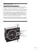
Figure 1-1 Recorder Description 5
Figure 1-2 Recorder Display 6
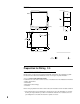
Figure 2-1 Installation Panel Dimensions Conduit Opening Locations 8
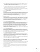
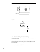
Figure 2-2 Noise Suppression 10
Figure 2-3 Noise Suppression 10
Figure 2-4 Board and Terminal Locations 13
Figure 2-5 AC Power Input 14
Figure 2-6 Thermocouple Inputs 14
Figure 2-7 RTD Inputs 14
Figure 2-8 Milliamp, Volt and Millivolt Inputs 15
Figure 2-9 Digital Communications 15
Figure 2-10A SPST Relay Output 16
Figure 2-10B SPDT Relay Output 16
Figure 2-11 SSR Output 16
Figure 2-12 Current Output 17
Figure 2-13 24 VDC Power Supply Option 17
Figure 3-1 Keypad Features 19
Figure 4-1 Changing Pens 33
Table 3-1 Enable Mode Configuration Procedure 24
Table 3-2 Program Mode Configuration Procedure 28
Table 3-3 Alarm Set Mode Configuration Procedure 32
Table 4-1 Calibration Procedure 35
Table 4-2 Test Procedures and Description 40
FLOW CHARTS
Flow - Alarm Set 32
Flow - Calibration 34
Flow - Enable 24
Flow - Program 25
Flow - Test 39