Form 2882 • Price $21.00 Edition 6 • © Dec.
nformation in this installation, wiring, and operation manual is subject to change without notice. One manual is provided with each instrument at the time of shipment. Extra copies are available at the price published on the front cover. I Copyright © December 1996, all rights reserved. No part of this publication may be reproduced, transmitted, transcribed or stored in a retrieval system, or translated into any language in any form by any means without the written permission of the Partlow-West Company.
TABLE OF CONTENTS SECTION 1 - GENERAL 1.1 Product Description PAGE NUMBER 5 SECTION 2 - INSTALLATION & WIRING 2.1 2.2 2.3 2.4 2.5 2.6 Installation & Wiring Unpacking Location Mounting Preparation for Wiring Wiring Connections 7 7 7 7 8 13 SECTION 3 - CONFIGURATION 3.1 3.2 3.3 3.4 3.5 Configuration (Set Up) Configuration/Jumper Positioning Operation Summary Start up Procedure Front Panel Operation 18 19 19 20 21 SECTION 4 - SERVICE 4.1 4.2 4.3 4.4 4.5 4.
FIGURES & TABLES Figure 1-1 Figure 1-2 Figure 2-1 Figure 2-2 Figure 2-3 Figure 2-4 Figure 2-5 Figure 2-6 Figure 2-7 Figure 2-8 Figure 2-9 Figure 2-10A Figure 2-10B Figure 2-11 Figure 2-12 Figure 2-13 Figure 3-1 Figure 4-1 Table 3-1 Table 3-2 Table 3-3 Table 4-1 Table 4-2 Recorder Description Recorder Display Installation Panel Dimensions Conduit Opening Locations Noise Suppression Noise Suppression Board and Terminal Locations AC Power Input Thermocouple Inputs RTD Inputs Milliamp, Volt and Millivolt Input
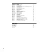
Product Description 1.1 1.1.1 GENERAL The instrument is a microprocessor based circular chart recorder capable of measuring, displaying and recording from a variety of inputs. Applications include temperature, pressure, flow and others. The instrument can be specified as either a single or dual pen unit. Recording, alarm, or limit settings and other parameters are easily entered via the keypad.
1.1.2 RECORDING The instrument records the selected process variable on a 10-inch circular chart. One box of standard charts is provided with each recorder. Charts are available in a wide selection of ranges. Chart rotation speed is programmable from 0.1 to 999.9 hours per revolution in 0.1 hour increments. The instrument can be ordered with one or two pens. Pen 1 is red and Pen 2 is green. Pens are the disposable fiber-tip type. 1.1.
Installation and Wiring 2.1 Read these instructions carefully before proceeding with installation and operation. Electrical code requirements and safety standards should be observed. Installation should be performed by qualified personnel. CAUTION: The Instrument AC power input is specified in the model number and on the wiring label affixed to the the top center of the platen. Verify the AC power input required by the instrument prior to proceeding with installation. Unpacking 2.
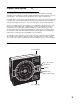
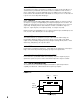
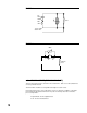
FIGURE 2-1 EC1 16 5 mm) 15 1 (384.2 mm) 8 21 2 (64 mm) 4 WIDTH OF COVER 2 19 (65.9 mm) 32 16 91m 9 32 DIA.(7.1mm) 12 85 71 2 (320.7 mm) (190.5 mm) 1 13 2 (342.5 mm) 13 15 ( 354 mm) 16 Panel cut-out for flush mounting 2.5" 63.5mm Preparation for Wiring 2.5 2.5.1 WIRING GUIDELINES Electrical noise is a phenomenon typical of industrial environments. The following are guidelines that must be followed to minimize the effect of noise upon any instrumentation. 2.5.1.
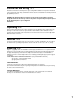
2. If possible, eliminate mechanical contact relay(s) and replace with solid state relays. If a mechanical relay being powered by an instrument output device cannot be replaced, a solid state relay can be used to isolate the instrument. 3. A separate isolation transformer to feed only instrumentation should be considered. The transformer can isolate the instrument from noise found on the AC power input. 4.
FIGURE 2-2 0.5 mfd 1000V Coil 220 ohms 115V 1/4W 230V 1W FIGURE 2-3 MOV R C Inductive Load 2.5.2 SENSOR PLACEMENT (THERMOCOUPLE OR RTD) Thermocouple lead resistance should not exceed 300 ohms. It this is exceeded, instrument accuracy could be affected. Two wire RTD's should be used only with lead lengths less than 10 feet. If the temperature probe is to be subjected to corrosive or abrasive conditions, it should be protected by the appropriate thermowell.
THERMOCOUPLE LEAD RESISTANCE Thermcouple lead length can affect instrument accuracy since the size (gauge) and the length of the wire affect lead resistance. To determine the temperature error resulting from the lead length resistance, use the following equation: Terr = TLe * L where; TLe = value from appropriate table below L = length of leadwire in thousands of feet TABLE 1 Temperature error in °C per 1000 feet of Leadwire AWG Thermocouple Type: No. J K T R S 10 .68 1.71 .76 2.05 2.12 12 1.08 2.68 1.
RTD LEAD RESISTANCE RTD lead length can affect instrument accuracy, since the size (gauge) and length of the wire affect lead resistance. To determine the temperature error resulting from the lead length resistance, use the following equation: Terr = TLe * L where; TABLE 3 3 Wire RTD AWG No. 10 12 14 16 18 20 24 TABLE 4 AWG No. 10 12 14 16 18 20 24 TLe = value from Table 3 if 3 wire RTD or Table 4 if 2 wire RTD L = length of lead wire in thousands of feet Error ° C +/-0.04 +/-0.07 +/-0.10 +/-0.
Wiring Connections 2.6 All wiring connections are typically made to the instrument at the time of installation. Connections should be made at the terminal blocks , two 12 gauge wires maximum. Terminal blocks are designated TB1 through TB13. See Figure 2-4 for the terminal block locations (SPST Relay Board shown).
FIGURE 2-5 AC Instrument Power Input Connect the 115 VAC hot and neutral to terminals 1 and 2 respectively of TB1. See Figure 2-4 (page 13) for Terminal Board locations on the instrument. Connect the 230 VAC one leg to each terminal, be sure to check the position of the Voltage Selector switch provided with 230 VAC instruments. The switch position must match the voltage input to the instrument.
FIGURE 2-8 Volt, Millivolt and milliamp Input Make the volt, millivolt or milliamp connections as shown below. Use TB4 for the Pen 1 input, and TB5 for the Pen 2 input. Terminal 1 is positive and terminal 2 is negative. The milliamp input requires the installation of an appropriate shunt resistor (ordered separately) between terminals 1 and 2. Be sure that input conditioning jumpers are in the correct positions for the input being connected. See Appendix A-1 (page 50).
2.6.4 OUTPUT CONNECTIONS Relay output(s) if provided in the instrument may be assigned to alarm output functions for Pen 1 and/or Pen 2 (if present) if instrument is recorder. Relay outputs, if instrument is a limit device, may be assigned to limit output functions. Current outputs may be assigned to process value retransmission output for Pen 1 and/or Pen 2 (if present). The assignment of the output function is accomplished in the Program mode, see Table 3-2 (page 28).
FIGURE 2-12 Current Output Connections are made to current outputs A thru D as shown. Each current output is programmable as either 4 to 20 mADC or 0 to 20 mADC. Each output must be assigned to the desired function (refer to Table 3-2, page 28, for details.) Terminal connections are made using TB10 through TB13 for current output A through D respectively. Connect positive lead (+) to terminal 1 and the negative lead (-) to terminal 2. Current outputs will operate up to 650 ohms maximum load.
Configuration 3.1 After completing installation and wiring of the instrument the configuration (set up) procedures must be performed to prepare the instrument for operation of the intended application. The procedures include selecting specific parameters, entering data and possible jumper positioning. Once properly configured the instrument will retain the user selections in memory. This procedure need not be repeated unless required by changes in the application.
Shipped Configuration/Jumper Positioning 3.2 Each instrument is factory shipped ready to accept a thermocouple input on TB 4 and TB 5. All configuration parameters in each mode are set to default values. These defaults are shown in tabular form after the description for each mode. Instrument AC power input is as specified in the instrument model number and is shown on the ratings label. The 230 VAC option includes a switch in the instrument for selecting either 230 VAC or115 VAC input power.
3.3.2 CONFIGURATION DISPLAYS Each pen specified is provided with its own 4 digit LED display. These are used during configuration to display the parameter codes and values. The display located in the upper right hand corner of the instrument is used to show the codes for Pen 1 and those that are common between Pens 1 and 2. The display in the lower right hand corner is used to show the configuration codes for Pen 2 (if provided).
Step 2B - For instruments with software revision r3.00 and above Upon power up, a brief flash on all displays (upper and, if equipped, lower) will occur to show the instrument is "alive". Then 7XXX will be displayed (X representing digits) then XXXX, then XXXX, identifying the twelve digit model number as defined in the order matrix. Next, the EPROM part number will be indicated P-XX. After the EPROM part number, the software revision level will be displayed in the format rX.XX followed by P.
3.5.2 KEYPAD CONTROLS The keys provided on the keypad and their functions include: SCROLL: Used to : UP: Used to: DOWN: Used to: RESET: Used to: (Limit Only) Advance the display through the enabled modes. While in a mode, used to sequence the parameter codes and values. Exit some Test and Calibration functions. Work in conjunction with other keys. Exit a mode. Turn a mode On in the Enable mode. Increase a numerical value Work in conjunction with other keys. Display the setpoint (Limit device only).
3.5.3 PROGRAM MODE CONFIGURATION PROCEDURE The Program mode provides a means to configure or reconfigure the instrument operation within the limits of the hardware specified and provided. Parameters to be configured will be only those that are applicable as determined by the hardware provided. Review the configuration procedures in Table 3-2 (page 28). Use the "Your Setting" column in the table to record your selections. 3.5.3.
3.5.4.2 MOVEMENT IN THE ALARM SET MODE Each time the DOWN key is pressed while a parameter code is being displayed another parameter code will be displayed. Pressing the SCROLL key while a parameter code is displayed will cause the parameter value to appear. Pressing the SCROLL key with a parameter value displayed will cause the next parameter code to be displayed. Pressing the UP key while a parameter code is being displayed will exit the Alarm Set mode and the ASEt code will appear in the display.
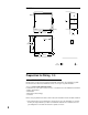
PROGRAM MODE FLOW CHART Prog Pen 1 & Pen 2 A inPS Prnd iCor dFF AL1 PFF AL2 Pout dPoS Pou Euu PoL EuL Cru HyAo CrL SPuL PAEC SPLL B Unit A 25
B KEY C rLyA Curb rLyb CurC rLyC Curd rLyd CoAr rLyE Cobr rLyF CoCr rLyg Codr rLyH Crt CurA PAPu C D Actual Display ON OFF On/Off Display Use arrow keys to turn on or off Scroll Key Numeric Display Use arrow keys to change value Up Arrow Key Down Arrow 26
D Coo Com (Optional) CCon CbS CAd1 CAd2 27
TABLE 3-2 PROGRAM MODE CONFIGURATION PROCEDURE Press the SCROLL key until Prog is displayed. Press the DOWN key to enter the Program mode. Pen 1 will be displayed in the upper display. To enter the Pen 1 parameter, press the DOWN key. To enter the Pen 2 parameter, if provided, press the Scroll key, then the DOWN key. To enter the unit parameter, press the SCROLL key with either Pen 1 or Pen 2 displayed until unit is displayed, then press the DOWN key.
DISPLAY AVAILABLE CODES SETTINGS FACTORY SETTING STEP DESCRIPTION 6 Decimal Position dPoS 0=None 0 1=One decimal position 2=Two decimal positions 3=Three decimal positions RTD and thermocouple inputs are limited to either 0 or 1 decimal positions 7 Engineering Units Upper Value (If Input Select = 30, 31, 32, 33, 34) Euu -9999 to 9999 1000 8 Engineering Units Lower Value (If Input Select = 30, 31, 32, 33, 34) EuL -9999 to 9999 0 9 Hysteresis for Alarm Outputs HyAo 0 to 300 degrees/units
STEP DESCRIPTION DISPLAY AVAILABLE CODES SETTINGS FACTORY SETTING Unit Parameters 21 30 Relay A Assignment rLyA 0=Not assigned 0 1=Assigned to Alarm 1-Pen 1 2=Assigned to Alarm 2-Pen 1 3=Assigned to Alarm 1-Pen 2 4=Assigned to Alarm 2-Pen 2 22 Relay B Assignment rLyb Same selection as rLyA 0 23 Relay C Assignment rLyC Same selection as rLyA 0 24 Relay D Assignment rLyd Same selection as rLyA 0 25 Relay E Assignment rLyE Same selection as rLyA 0 26 Relay F Assignment rLyF Same
STEP DESCRIPTION DISPLAY AVAILABLE CODES SETTINGS FACTORY SETTING YOUR SETTING Communications Options Parameters 40 Communication Configuration CCon 0=Off 3 1=Monitor Mode (Read Only) 2=Normal Mode (Read and Write) 3=Total Access with Limit Checking 4=Total Access without Limit Checking 41 Communication Bit Rate Selection CbS 1 to 6 1=300 2=600 3=1200 4=2400 5=4800 6=9600 6 42 Communications Address-Pen 1 CAd1 0 to 99 1 43 Communications Address-Pen 2 CAd2 0 to 99 2 31
ALARM SET FLOW CHART ASEt KEY Actual Display PAL1 ON OFF On/Off Display Use arrow keys to turn on or off PAL2 Scroll Key Numeric Display Use arrow keys to change value Up Arrow Key Down Arrow TABLE 3-3 ALARM SET MODE CONFIGURATION PROCEDURE Press and release the SCROLL key until ASEt is displayed, then press the DOWN key. Press the SCROLL key to advance the display through the parameters and their values. Use the UP and DOWN keys to select (adjust) the values.
Service 4.1 This section contains information regarding calibration and test procedures that can be performed in the field as well as items concerning the normal maintenance of the instrument. Changing Charts 4.2 Chart changes may be done while in the normal operating mode. CAUTION: The chart flange assembly pin is sharp to perforate the chart. Use caution while installing the chart to avoid coming into contact with the pin. 1. Depress and hold the UP and DOWN keys for between 2 and 3 seconds.
Calibration 4.4 CAUTION: Do not attempt any calibrations without the proper test equipment that meets or exceeds the specifications listed. Press and release the SCROLL key until CAL appears on the display , then press the DOWN key to enter the mode. The display will change to CAL1. Press the SCROLL key to advance the display to the other calibration modes available. For two pen units, CAL2 and CAL 3 will only need to be required on TB4 input.
TABLE 4-1 CALIBRATION PROCEDURES Calibration Procedure CAL 1 Description Reinitialization of program and tuning values. CAL 2 Main calibration necessary for all input types. CAL 3 Cold Junction Compensation calibration used to correct for component variation in the CJC circuit. Necessary for thermocouple inputs. CAL 4 Cold Junction Utility, displays temperature the cold junction compensator is sensing. No adjustment is made with this procedure. CAL 5 RTD input calibration.
Error recovery: See section 4.6 (page 43) for details. Insure that the millivolt source is connected correctly and functioning properly. The calibration can be exited when hLd1 or the calibration reference number is displayed by pressing the SCROLL key. CAL2 QUICK CALIBRATION This routine will allow the operator to execute a rough calibration on their unit via the keypad with no other equipment or disturbance to established wiring.
4.4.5 CAL 5 RTD INPUT This procedure determines and saves calibration values relating to RTD inputs. This calibration must be preceded by CAL 2 to properly calibrate the instrument. Both RTD inputs must be calibrated and both inputs must have valid inputs during the calibration. Decade boxes with .01% resolution or equivalent are required. Make sure that the Processor board jumpers JU4, JU6 and JU5, JU7 are in the proper positions. See Appendix A-1 (page 50).
4.4.7 CAL 9 PEN CALIBRATION This procedure is used to calibrate the pen(s). No special test equipment required. Valid inputs must be connected to TB 4 and TB 5 before performing this calibration. With CAL 9 displayed, push and hold the DOWN key, then press the SCROLL key . Release both keys and the display will indicate PEn1. For 2 Pen instruments, press the DOWN key to toggle the display between pen 1 and pen 2. With desired pen displayed, press the SCROLL key. FOR INSTRUMENTS WITH SOFTWARE REVISION R2.
Test Mode 4.5 To enter the Test mode, press and release the SCROLL key until tESt appears on the display then press the DOWN key. tSt1 will be displayed, press and release the SCROLL key to advance the display to the desired test. Tests 1, 2 and 3 are performed as a unit so the display will advance directly to tSt4 from tSt1. Listed in Table 4-2, page 40, are the test procedures available. Test 1, 2 and 3 are performed on start up, periodically during operation, and on entry into the Test mode.
TABLE 4-2 TEST PROCEDURES AND DESCRIPTION Test Test 1 Description Microprocessor internal RAM test. Used to check the processor RAM to make sure it is functioning correctly. Test 2 External RAM test, used to test the RAM chip for proper function. Test 3 EPROM checksum test, used to check that the EPROM program is correct. Test 4 External RAM checksum test; instrument test and identifies how many times Errors16 or 17 have occurred.
4.5.5 TEST 5 KEYPAD/DISPLAY TEST This test allows the operator to verify that the keys work and that all display elements can be lighted. No special test equipment is required. With tSt5 displayed, press and hold the DOWN key, then press the SCROLL key and then release both keys. The display will go blank.
The current output reading should be ± 0.1 mADC at any output value. A ± 5 % of span adjustment for the current output(s) is provided by using the potentiometer adjacent to the current output on the Current Output board. See Appendix A-4 (page 53). To exit the test, press the SCROLL key and tSt7 will be displayed. The existence of a mADC current output is dependent upon the hardware configuration. 4.5.
Trouble-shooting and Diagnostics 4.6 The Trouble-shooting Guidelines Section consists of two columns. The first column is a list of some possible instrument conditions. The second column is a list of steps that should improve the condition. The steps should be performed in order until the condition improves or all the steps have been completed. If the instrument condition has not improved, contact the nearest representative or the factory for assistance.
Model Number Displayed during power up is incorrect 1. Turn off the instrument power, wait 5 seconds then reapply the power. Verify that the number displayed during the power up sequence is the same as indicated on the label affixed to the platen. If the number displayed is incorrect perform the following steps: a. Turn off the power to the instrument. Press and hold the UP and DOWN keys.
5. If the output appears not to turn off remove the power to the instrument. Open the cover and loosen the platen hold down screw. Swing the platen open. Clip the resistor located on the Relay Board adjacent to the output(s) that seem to stay on (See Appendix A-2, page 51). A .01 microfarrad, 1 KV capacitor should be connected from the terminal listed below, for the output where the resistor indicated was removed, to the AC ground.
4. For software revision R2.99 and below, perform Test 9 as described in the Test Section of the manual (page 42). If the pen feedback voltage does not vary, check the pen Potentiometer Segment board for proper ribbon cable connection to the Processor board (Appendix A-1, page 50) and that the pen position fingers are making contact with Potentiometer Segment board. 5. For software revision R2.99 and below, inspect to see that the Potentiometer Segment of the pen feed back is clean.
Er 2 - External RAM Failure 1. Turn off the power to the instrument. Wait 5 seconds, and turn the power on. Er 3 - EPROM Checksum Failure 1. Perform the steps listed for Er 1 except that the EPROM (U7) on the Processor board should be inspected. Er 4 - RTD Mismatch Error 1. Check the connections to the instrument for the RTD Input Calibration (CAL5) as described in the Calibration section (page 37). Repeat the RTD Input Calibration. Er 5 - No Zero Crossings Detected 1.
Er12 - CAL2 Voltage Error 1. Check that 50 mVDC is properly connected to the instrument and is within the tolerance limits as indicated in the CAL2 procedure of the Calibration section (page 35). 2. Turn off the power to the instrument and open the cover. Loosen the platen hold down screw and swing the platen open. Inspect the Processor board (Appendix A-1, page 50) to insure that the input conditioning jumper JU4 is in the non-volt position. 3.
Momentary ER 70 Controller unable to respond within 250 milliseconds 1. May occur when incrementing or decrementing a value. Error clears itself. Momentary ER 71 Byte received before the response was transmitted 1. Computer program must wait longer for a response from the instrument. Momentary Er 72 Incorrect Block Check character was received 1. Data received not valid, possible corruption on the comm line. Possible noise problems.
Appendix A Board Layout - Jumper Positioning FIGURE A-1 - PROCESSOR BOARD Top SWI for Rev. Y and above SWI for Rev.
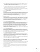
FIGURE A-2 - SPST RELAY/SSR DRIVER OUTPUT BOARD TB6 TS1 R1 TB7 TS2 R2 TS3 R3 TB8 TS4 R4 TS5 R5 TS6 R6 C1 C2 C3 C4 C5 C6 K1 K2 K3 K4 K5 K6 (rly D) (rly E) (rly F) (rly A) (rly B) (rly C) P7 TB9 (rly G) If the relay is connected to a high impedance AC device, the snubber network used to protect the relay contact may cause the output to appear to be activated when the relay is off. To cure the problem, cut the snubber resistor for the output that is being affected.
FIGURE A-3 - SPDT RELAY/SSR DRIVER OUTPUT BOARD TB6 TS1 R1 TB7 TS2 C1 R2 C2 TS3 TB8 TS4 R3 C3 R4 TS5 R5 TS6 R6 C5 C6 K3 K4 (rly C) (rly D) C4 K1 K2 (rly A) (rly B) P7 TB9 (rly G) If the relay is connected to a high impedance AC device, the snubber network used to protect the relay contact may cause the output to appear to be activated when the relay is off. To cure the problem, cut the snubber resistor for the output that is being affected.
FIGURE A-4 - CURRENT OUTPUT BOARD R50 U2 U4 U3 U5 TB10 TB11 R51 R52 R53 U6 U8 U7 U9 U1 TB12 TB13 If this option board was ordered, you will find it located in the lower right hand corner of the instrument.
Appendix B Glossary DISPLAY FILTER FACTOR This parameter is adjustable from 1 to 20 which represents the number of scans per second of the process variable that are averaged together before updating the displayed and recorded value. The factory default value is 1 = no filtering. Display code dFF. HYSTERESIS This parameter is adjustable from 0 to 300 units representing the width of the band (half above and half below setpoint). Used with Alarm outputs to reduce cycling.
Appendix C - Order Matrix 7 0 0 PEN 1 OPTION SUFFIX 1 Recorder Only 4 High/Low Limit Blank N3 AW AD AE PEN 2 0 None 1 Recorder only None NEMA 3 † RTD Depression on Pen 2 0/100 mVDC Input N3 plus AW VOLTAGE *RELAY OUTPUTS 0 1 2 4 6 7 8 None One SPST Two SPST Four SPST Six SPST One SPDT Two SPDT 9 Two SPDT and Two SPST *SSR DRIVER OUTPUTS 0 1 2 4 6 8 None One Two Four Six Eight 4 TO 20MA OUTPUTS 0 1 2 3 4 None One Standard Two Standard Three Standard Four Standard 1 115VAC Input 2 115/230 VAC I
Appendix D - Specifications Measurement Error Limit • Type J, K, T, E, N, C T/C's and RTD +/- 0.25% of reading plus 1 degree @ 25 degrees C • Type R, S, B T/C's +/- 0.25% of span @ 25 degrees C • mA, mV, and VDC +/- 0.25% of scaled span plus 1 Whole Digit @ 25 degrees C 56 Ambient Temperature Error 0.01% of span per degree C deviation from 25 derees C Scan Rate 1 scan/second Display Decimal Positions One, two or three decimal places (0.
Input Specifications THERMOCOUPLE TYPE RANGE TYPE RANGE J 0 to 760 C 0 to 1400 F E 0 to 750 C 0 to 1400 F K 0 to 1360 C 0 to 2500 F B 200 to 1800 C 400 to 3300 F T -220 to 400 C -330 to 750 F N 0 to 1300 C 0 to 2370 F R 200 to 1650 C 400 to 3000 F C 200 to 2300 C 390 to 4170 F S 200 to 1650 C 400 to 3000 F MILLIAMPS VOLTS RTD 4-20mADC (with resistor) 0 to 5VDC 1 to 5 VDC 100 OHM (.
RECORD Chart 10 inch circular chart; 100 charts furnished with each instrument if standard range Chart Range -9999 to 9999 degrees/units Chart Drive DC stepper motor Chart Rotation User configurable from 0.1 to 999.9 hours per revolution Pen Type Disposable Fiber-tip Pen Color Pen 1 - Red Pen 2 - Green Pen Response Time < 9 seconds over chart span Accuracy ± 1.0% of chart span max., error from displayed value. Chart Rotation Accuracy ± .
Appendix E Software Reference Sheet PROGRAM MODE Pen 1 Pen 2 ENABLE MODE EtSt ECAL EPro EASt ESPC ALARM SET Pen 1 PAL1 PAL2 Pen 2 inPS iCor AL1 AL2 disP dPoS Euu EuL HyAo SPuL SPLL Prnd dFF PFF Pout Pou PoL Cru CrL PAEC rLyA rLyb rLyC rLyd rLyE rLyF rLyg rLyH CurA Curb CurC Curd CoAr Cobr CoCr Codr Crt PAPu Coo CCon CbS CAd1 CAd2 unit 59
Warranty and Return Statement These products are sold by The Partlow-West Company under the warranties set forth in the following paragraphs. Such warranties are extended only with respect to a purchase of these products, as new merchandise, directly from The Partlow-West Company or from a PartlowWest Company distributor, representative or reseller, and are extended only to the first buyer thereof who purchases them other than for the purpose of resale.