
Owner manual


19
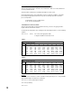
FIGURE 2-13
SSR Driver Output
Connections are made to relays H through A as shown. Terminal connections are made using
TB9, TB8, etc. depending on the number of SSR Driver outputs specified.
FIGURE 2-14
Current Output
Connections are made to current outputs A through D as shown. Each current output is
programmable as either 4 to 20 mADC or 0 to 20 mADC. Each output must be assigned to the
desired function in the Program mode. Terminal connections are made using TB10 through
TB13 for current output A through D respectively. Connect positive lead (+) to terminal 1 and
the negative lead (-) to terminal 2. Each current output will operate up to a 650 ohms
maximum load.
1234
SSR
+
-
TB6 THRU TB
9
12
SHIELDED
TWISTED
PAIR
LOAD
+
-
650 OHMS
MAXIMUM