Form 2877 • Price $32.00 Edition 7 • © Dec.
I nformation in this installation, wiring, and operation manual is subject to change without notice. One manual is provided with each instrument at the time of shipment. Extra copies are available at the price published on the front cover. Copyright © December 1996, all rights reserved. No part of this publication may be reproduced, transmitted, transcribed or stored in a retrieval system, or translated into any language in any form by any means without the written permission of The Partlow-West Company.
TABLE OF CONTENTS SECTION 1 - GENERAL 1.1 Product Description PAGE NUMBER 5 SECTION 2 - INSTALLATION & WIRING 2.1 2.2 2.3 2.4 2.5 2.6 Installation & Wiring Unpacking Location Mounting Preparation for Wiring Wiring Connections 8 8 8 8 9 14 SECTION 3 - CONFIGURATION 3.1 3.2 3.3 3.4 3.5 Configuration (Set Up) Configuration/Jumper Positioning Operation Summary Start Up Procedures Front Panel Operation 20 21 21 21 22 SECTION 4 - OPERATION 4.1 Off Control Mode 4.2 Alarm Operation 4.
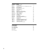
FIGURES & TABLES Figure 1-1 Figure 1-2 Figure 2-1 Figure 2-2 Figure 2-3 Figure 2-4 Figure 2-5 Figure 2-6 Figure 2-7 Figure 2-8 Figure 2-9 Figure 2-10 Figure 2-11A Figure 2-11B Figure 2-12 Figure 2-13 Figure 2-14 Figure 2-15 Figure 3-1 Figure 5-1 Table 3-1 Table 3-2 Table 3-3 Table 5-1 Table 5-2 Recorder Description Recorder Display Installation Panel Dimensions Conduit Opening Locations Noise Suppression Noise Suppression Board and Terminal Locations AC Power Input Thermocouple Inputs RTD Inputs Milliamp,
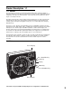
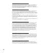
Product Description 1.1 1.1.1 GENERAL The instrument is a microprocessor based circular chart Recorder Controller capable of measuring, displaying, recording and controlling from a variety of inputs. Applications include temperature, level, pressure, flow and others. The instruments can be specified as either a single or as a dual pen model. Recording, control functions, alarm settings and other parameters are easily entered via the keypad.
1.1.2 RECORDING The instrument records the selected process variable on a 10-inch circular chart. One box of standard charts is provided with each recorder. Charts are available in a wide selection of ranges. Chart rotation speed is programmable from 0.1 to 999.9 hours per revolution in 0.1 hour increments. The instrument can be ordered with one or two pens. Pen 1 is red and Pen 2 is green. Pens are the disposable fiber-tip type. 1.1.
1.1.7 DIGITAL COMMUNICATIONS The instrument can be ordered with a Digital Communications option that provides the capability of bi-directional communications with a supervisory computer. A dual pen instrument can have an individual address selected for each pen. Refer to the Communications Protocol Manual (Form 2878) for more details regarding the communications option. This manual is included with the unit when the communications option is specified.
Installation and Wiring 2.1 Read these instructions carefully before proceeding with installation and operation. Electrical code requirements and safety standards should be observed. Installation should be performed by qualified personnel. CAUTION: The Instrument AC power input is specified in the model number and on the wiring label affixed to the the top center of the platen. Verify the AC power input required by the instrument prior to proceeding with installation. Unpacking 2.
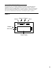
FIGURE 2-1 7/8" Dia hole for wiring - 3 locations, EC1, EC2, and EC3 EC3 EC1 13 3 16 (335 mm) EC2 15 1 (384.2 mm) 8 21 2 4 PLACES 3 43 (64 mm) 11 16 (119.1 mm) 4 WIDTH OF COVER 2 19 (65.9 mm) 32 Mounting Bracket (2) 9 32 DIA.(7.1mm) Holes to mount bracket to surface 5 12 8 71 2 (320.7 mm) (190.5 mm) Screw that mounts to case 1 13 2 (342.5 mm) 15 ( 354 mm) 13 16 7 32 (5.5 mm) Note: Surface Mount Dimensions Top edge of case Panel cut-out for flush mounting 7 3/4" 196.9mm 2.5" 63.
3. A separate isolation transformer to feed only instrumentation should be considered. The transformer can isolate the instrument from noise found on the AC power input. 4. If the instrument is being installed on existing equipment, the wiring in the area should be checked to insure that good wiring practices have been followed. 2.5.1.2 AC POWER WIRING Earth Ground The instrument includes noise suppression components that require an earth ground connection to function.
FIGURE 2-2 0.
2.5.2 SENSOR PLACEMENT (THERMOCOUPLE OR RTD) If the temperature probe is to be subjected to corrosive or abrasive conditions, it should be protected by the appropriate thermowell. The probe should be positioned to reflect true process temperature: In liquid media - the mose agitated area. In air - the best circulated area. THERMOCOUPLE LEAD RESISTANCE Thermocouple lead length can affect instrument accuracy, since the size (gauge) and the length of the wire affect lead resistance.
RTD LEAD RESISTANCE RTD lead length can affect instrument accuracy. Size (gauge) and length of the wire used affects lead length resistance. To determine the temperature error resulting from the lead length resistance, use the following equation: Terr = TLe * L where; TABLE 3 3 Wire RTD AWG No. 10 12 14 16 18 20 24 TABLE 4 AWG No. 10 12 14 16 18 20 24 TLe = value from Table 3 if 3 wire or Table 4 is 2 wire. L = length of leadwire in thousands of feet. Error °C +/-0.04 +/-0.07 +/-0.10 +/-0.16 +/-0.
Wiring Connections 2.6 All wiring connections are typically made to the instrument at the time of installation. Connections are made at the terminal boards provided, two 12 gauge wires maximum. Terminal boards are designated TB1 through TB13. See Figure 2-4 for the terminal board locations. The number of terminal boards present on the instrument depend upon the model number/ hardware configuration.
FIGURE 2-5 AC Instrument Power Input Connect the 115 VAC hot and neutral to terminals 1 and 2 respectively of TB1. See Figure 2-4 (page 14) for Terminal Board locations on the instrument. Connect the 230 VAC one leg to each terminal, be sure to check the position of the Voltage Selector switch provided with 230 VAC instruments. The switch position must match the voltage input to the instrument.
FIGURE 2-8 Volt, Millivolt and milliamp Input Make the volt, millivolt and milliamp connections as shown below. Use TB4 for thePen 1 input, and TB5 for the Pen 2 input. Terminal 1 is positive and terminal 2 is negative. The milliamp input requires the installation of an appropriate shunt resistor (ordered separately) between terminals 1 and 2. Be sure that input conditioning jumpers are in the correct positions for the input being connected. See Appendix A-1 (page 62).
FIGURE 2-10 Digital Communications Options Connections are made as shown using TB2. Refer to the Protocol Manual, Form #2878 for more details regarding the connections and how to use this option. This document is provided only when this option has been specified. If the communications network continues on to other instruments, connect the cable shields together, but not to the instrument. A terminating resistor should be installed at the terminals of the last unit in the communications loop.
FIGURE 2-11B SPDT Relay Output HOT NEU LOAD 1 2 3 N.O. C N.C. POWER 5 AMPERES MAXIMUM AT 115 VAC TB6 Relay A TB7 Relay B FIGURE 2-12 SSR Driver Output Connections are made to relays H through A as shown. Terminal connections are made using TB9, TB8, etc. depending on the number of SSR Driver outputs specified. + 1 2 3 4 TB6 THRU TB9 - SSR FIGURE 2-13 Current Output Connections are made to current outputs A thruough D as shown.
FIGURE 2-14 Transmitter Power Supply Input If the isolated 24 VDC regulated transmitter power supply has been specified, the connections should be made as shown. Connections are made using TB3, terminal 1 is positive and terminal 2 is negative. The power supply is capable of providing the power needed by up to 2 transducers (40 mADC maximum).
Configuration 3.1 After completing installation and wiring of the instrument the configuration (set up) procedures must be performed to prepare the instrument for operation on the intended application. The procedures include selecting specific parameters, entering data and possible jumper positioning. Once properly configured the instrument will retain the user selections in memory so this procedure need not be repeated unless required by changes in the application.
Shipped Configuration/Jumper Positioning 3.2 Each instrument is factory shipped ready to accept a thermocouple input on TB 4 and TB 5. All parameters in each mode are set to default values. These defaults are shown in tabular form after the description for each mode. Instrument AC power input is as specified in the instrument model number and is shown on the ratings label. The 230 VAC option includes a switch in the instrument for selecting either 230 VAC or115 VAC input power.
3.4.1 POWER UP PROCEDURE Step 1 Verify that all electrical connections have been properly made before applying power to instrument. the Step 2A - For instruments with software revision R2.99 and below Upon power up, 7XXX will be displayed (X representing digits), then XXXX, then XXXX, identifying the twelve digit model number as defined in the order matrix. Next, the EPROM part number will be indicated P-XX. After the EPROM part number, the software revision level will be displayed in the format rX.
3.5.2 KEYPAD CONTROLS The keys on the keypad functions include: SCROLL: Used to : 1. Display the enabled modes. 2. While in a mode, used to sequence the parameter codes and values. 3. Exit some Test and Calibration functions 4. Work in conjunction with other keys: a. With the UP key to display proportional output % b. With the DOWN Key; 1) On power up to alter model # 2) Enter Cal/Test functions UP: Used to: 1. 2. 3. 4. 5. 6. Exit a mode.
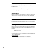
FIGURE 3-1 Pen 1 AUTO/MAN Key SCROLL Key UP Key Pen 2 AUTO/MAN Key DOWN Key LAMP TEST From the Off or Control modes, all display and status LEDs can be illuminated simultaneously by depressing the UP and DOWN keys at the same time. Any defective LEDs will not light. CHANGE CHART (also see Changing Charts, Section 5.2) If the UP and DOWN keys are held depressed for more than 2 seconds but less than 4 seconds, the display will show CChg momentarily.
PROGRAM MODE FLOW CHART Prog A inPS AL2 iCor diSP out1 dPoS o1uL Euu o1LL EuL out2 HyCo o2uL HyAo o2LL KEY rSP Actual Display AL1 A rSPu B ON OFF On/Off Display Use arrow keys to turn on or off Scroll Key Numeric Display Use arrow keys to change value Up Arrow Key Down Arrow 25
B C rSPL PoL SPuL Cru SPLL CrL AtFr P1EC Prnd P2EC dFF PAEC PFF rLyA Actual Display Pout rLyb On/Off Display Use arrow keys to turn on or off Pou rLyC KEY ON OFF Scroll Key C Numeric Display Use arrow keys to change value Up Arrow Key Down Arrow 26 D
D E rLyd Cobr rLyE CoCr rLyF Codr rLyg Crt rLyH PAPu CurA C00 Com (Optional) Curb CCon CurC Cbs Curd CAd1 CoAr CAd2 E 27
TABLE 3-1 PROGRAM MODE CONFIGURATION PROCEDURE Press the SCROLL key until Prog is displayed. Press the DOWN key to enter the Program mode. Pen 1 will be displayed in the upper display. To enter the Pen 1 parameter, press the DOWN key. To enter the Pen 2 parameter, if provided, press the SCROLL key, then the DOWN key. To enter the unit parameter, press the SCROLL key with either Pen 1 or Pen 2 displayed until unit is displayed, then press the DOWN key.
DISPLAY AVAILABLE CODES SETTINGS FACTORY SETTING YOUR SETTING STEP DESCRIPTION 4 Output 1 Percent Upper Limit (o1uLand o1LL will not be seen if out1 = 0,1,2) o1uL 0 to 100 percent 100 5 Output 1 Percent Lower Limit o1LL 0 to 100 percent 0 6 Output 2 out2 0 = None (Position 0 Proportioning - Direct Closed) 1=On-Off- Direct 2=On-Off- Reverse 3=Time Proportioning- Direct 4=Time Proportioning-Reverse 5=Current Proportioning- Direct 6=Current Proportioning -Reverse 7=Position Proportioning (Rev
DISPLAY AVAILABLE CODES SETTINGS FACTORY SETTING STEP DESCRIPTION 16 Hysteresis for Alarm Outputs HyAo 0 to 300 Width of Hysteresis Band (see page 66 for definition) 3 17 Remote Setpoint If rSP is set to zero then rSPu and rSPL are not seen rSP 0 to 2 0=Not Used 1=1 to 5 VDC 2=0 to 5 VDC 0 18 Remote Setpoint Upper Value rSPu -9999 to 9999 1400 19 Remote Setpoint Lower Value rSPL -9999 to 9999 0 20 Setpoint Upper Limit SPuL -9999 to 9999 1400 21 Setpoint Lower Limit SPLL -
STEP DESCRIPTION 33 Pen Action on Error Condition DISPLAY AVAILABLE CODES SETTINGS PAEC FACTORY SETTING YOUR SETTING 0 or 1 1 0 = Pen goes to 0 % of chart 1 = Pen goes to 100 % of chart Pressing the SCROLL key with the PAEC parameter value displayed in the Pen 1 window will advance the display of a single pen instrument to the unit parameters. Pressing the SCROLL key with the PAEC parameter displayed in the Pen 1 window of a two pen instrument will advance the display to be PEns in the Pen 2 window.
DISPLAY AVAILABLE CODES SETTINGS FACTORY SETTING STEP DESCRIPTION 47 Current Output B Range Cobr Same selection as CoAr 1 48 Current Output C Range CoCr Same selection as CoAr 1 49 Current Output D Range Codr Same selection as CoAr 1 50 Chart Rotation Time Crt 0.1 to 999.9 hours per rotation 1.
TUNE MODE FLOW CHART tunE A SoP rSEt PAL1 ArSt dAL1 rAtE bAL1 Ct1 PAL2 Ct2 dAL2 SEnS bAL2 FoP Key Pb1 Actual Display ON OFF Pb2 On/Off Display Use arrow keys to turn on or off Scroll Key A Numeric Display Use arrow keys to change value Up Arrow Key Down Arrow 33
TABLE 3-2 TUNE MODE CONFIGURATION PROCEDURE The Tune mode allows the entry, review or altering of the process control Tune adjustments and alarm setting(s). To enter the Tune mode, press and release the SCROLL key until tunE is displayed, then press the DOWN key. Press the SCROLL key to advance the display through the parameters and their values. Use the UP and DOWN keys to select (adjust) the values.
DISPLAY AVAILABLE CODES SETTINGS FACTORY SETTING STEP DESCRIPTION 11 Automatic Reset Integration (Will be seen if Pb1 or Pb2 was shown) ArSt 0.0 to 100.0 repeats per minute 0.0 12 Rate Derivative (Wll be seen if Pb1 or Pb2 was seen) rAtE 0.0 to 10.0 minutes 0.
TABLE 3-3 ENABLE MODE CONFIGURATION PROCEDURE To enter the Enable mode, press the UP and DOWN keys while in CtrL or oFF modes. All the display lamps will light. After 2 seconds, the display will show Cchg and the pen(s) will move to and remain at a point above the top graduation on the chart. Continue to press the UP and DOWN keys, after 2 additional seconds, the display will show P dn and the Pen(s) are driven below the bottom graduation on the chart. After 6 more seconds, the display will show EnAb.
Operation 4.1 4.1.1 OFF MODE In the Off mode, the instrument control and alarm function (s) are turned off. Process Retransmission signal(s) remain active. The chart rotation can be selected in the Program mode to stop or continue to rotate when the instrument is in the Off mode. The pen(s) will remain active. The Off mode can be entered by pressing and releasing the SCROLL key until the display reads oFF, then pressing the DOWN key.
Dual Pen Instruments: If the instrument is specified and provided with the Remote Setpoint capability for either or both pens and the Remote Setpoint has been properly configured in the Program mode for either or both pens, the Setpoint Select mode will be accessible, if enabled. Press and release the SCROLL keys until SPS appears in the display, then press the DOWN key. The upper display will light and the lower display will blank if pen 1 is selected for a remote setpoint.
4.1.2.4 TIME PROPORTIONING CONTROL Time Proportioning Control can be implemented on controllers provided with SPST relay or SSR driver output(s). Time proportioning can be programed for output 1 and/or 2 for each pen. Time proportioning control is accomplished by cycling the output On and Off when the process value is within the proportional bandwidth selected at a prescribed time period. The time period is selected in the Tune mode by adjusting Ct1 and/or Ct2. The On time is a percentage of the Cycle Time.
4.1.2.7 PROPORTIONAL OUTPUT PERCENTAGE DISPLAY While in the Control mode, pressing the UP and the SCROLL keys at the same time will cause the display to sequence through a series of display codes and values: Po1 Po2 Proc Percent Output (if applicable) Percent Output (if applicable) Process Value Output 1% value Output 2% value Actual Process Value Each code and output value will be displayed only if the corresponding proportional output is present. Each code or value will be displayed for 1 second.
STANDBY MODE FLOW CHART Stby KEY Actual Display Po1 ON OFF On/Off Display Use arrow keys to turn on or off Scroll Key Po2 Numeric Display Use arrow keys to change value Up Arrow Key Down Arrow Alarm Operation 4.2 There are two alarms available per pen. The type of alarm is selected in the Program mode as follows: 1. Process Alarm Direct - the alarm will be On if the process value is greater than the process value selected. 2.
Tune Mode Operation 4.3 Proportional output controllers may require the adjustment (tuning) of the PID and other related parameters. This provides a means for the instrument's control algorithm to be adjusted to meet specific application requirements. 4.3.1 SYSTEMATIC TUNING METHOD 1. Changes in tuning parameters should be made one at a time. 2. After making any changes in tuning parameters, a disturbance should be introduced into the process so that the process reaction may be observed.
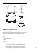
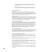
4.3.2 ZIEGLER NICHOLS TUNING METHOD This procedure has been determined empirically to yield ideal 1/4 amptitude decay tuning parameters that are determined by watching the system in a sustained oscillation (curve C, page 44, the ultimate proportional band and ultimate time period) and then using these values from this sustained oscillation to calculate ideal parameters. To aid in determining the process oscillation, the instrument configuration parameters can be adjusted.
Period C B A Curve A : unstable Curve B : stable Curve C : continuously cycling, ultimate PB and period 44
Service 5.1 This section contains information regarding calibration and test procedures that can be performed in the field as well as items concerning the normal maintenance of the instrument. Changing Charts 5.2 Chart changes may be done while in the normal operating mode. CAUTION: The chart flange assembly pin is sharp to perforate the chart. Use caution while installing the chart to avoid coming into contact with the pin. 1. Depress and hold the UP and DOWN keys for between 2 and 3 seconds.
Calibration 5.4 CAUTION: Do not attempt any calibrations without the proper test equipment that meets or exceeds the specifications listed. Press and release the SCROLL key until CAL appears on the display , then press the DOWN key to enter the mode. The display will change to CAL1. Press the SCROLL key to advance the display to the other calibration modes available. For two pen units, CAL5 will only need to be required on TB4 to calibrate Pen 1 and Pen 2 inputs.
TABLE 5-1 CALIBRATION PROCEDURES Calibration Procedure CAL 1 Description Reinitialization of program and tuning values. CAL 2 Main calibration necessary for all input types. CAL 3 Cold Junction Compensation calibration used to correct for component variation in the CJC circuit. Necessary for thermocouple inputs. CAL 4 Cold Junction Utility, displays temperature the cold junction compensator is sensing. No adjustment is made with this procedure. CAL 5 RTD input calibration.
Error recovery: See section 5.6 (page 55) for details. Ensure that the millivolt source is connected correctly and functioning properly. The calibration can be exited when hLd1 or the calibration reference number is displayed by pressing the SCROLL key. CAL2 QUICK CALIBRATION This routine will allow the operator to execute a rough calibration on their unit via the keypad with no other equipment or disturbance to established wiring.
5.4.5 CAL 5 RTD INPUT This procedure determines and saves calibration values relating to RTD inputs. This calibration must be preceded by CAL 2 to properly calibrate the instrument. Both RTD inputs must be calibrated and both inputs must have valid inputs during the calibration. Decade boxes with .01% resolution or equivalent are required. Make sure that the Processor board jumpers JU4, JU6 and JU5, JU7 are in the proper positions. See Appendix A-1 (page 62).
5.4.7 CAL 9 PEN CALIBRATION This procedure is used to calibrate the pen(s). No special test equipment required. Valid inputs must be connected to TB 4 and TB 5 before performing this calibration. With CAL 9 displayed, push and hold the DOWN key, then press the SCROLL key . Release both keys and the display will indicate PEn1. For 2 Pen instruments, press the DOWN key to toggle the display between pen 1 and pen 2. With desired pen displayed, press the SCROLL key. FOR INSTRUMENTS WITH SOFTWARE REVISION R2.
Test Mode 5.5 To enter the Test mode, press and release the SCROLL key until tESt appears on the display then press the DOWN key. tSt1 will be displayed, press and release the SCROLL key to advance the display to the desired test. Tests 1, 2 and 3 are performed as a unit so the display will advance directly to tSt4 from tSt1. Listed in Table 5-2, page 52, are the test procedures available. Test 1, 2 and 3 are performed on start up, periodically during operation, and on entry into the Test mode.
TABLE 5-2 TEST PROCEDURES AND DESCRIPTION Test Test 1 Description Microprocessor internal RAM test. Used to check the processor RAM to make sure it is functioning correctly. Test 2 External RAM test, used to test the RAM chip for proper function. Test 3 EPROM checksum test, used to check that the EPROM program is correct. Test 4 External RAM checksum test; instrument test and identifies how many times Errors16 or 17 have occurred.
5.5.5 TEST 5 KEYPAD/DISPLAY TEST This test allows the operator to verify that the keys work and that all display elements can be lighted. No special test equipment is required. With tSt5 displayed, press and hold the DOWN key, then press the SCROLL key and then release both keys. The display will go blank.
The current output reading should be ± 0.1 mADC at any output value. A ± 5 % of span adjustment for the current output(s) is provided by using the potentiometer adjacent to the current output on the Current Output board. See Appendix A-4 (page 65). To exit the test, press the SCROLL key and tSt7 will be displayed. The existence of a mADC current output is dependent upon the hardware configuration. 5.5.
Trouble-shooting and Diagnostics 5.6 The Trouble-shooting Guidelines Section consists of two columns. The first column is a list of some possible instrument conditions. The second column is a list of steps that should improve the condition. The steps should be performed in order until the condition improves or all the steps have been completed. If the instrument condition has not improved, contact the nearest representative or the factory for assistance.
Model Number Displayed during power up is incorrect 1. Turn off the instrument power, wait 5 seconds then re-apply the power. Verify that the number displayed during the power up sequence is the same as indicated on the label affixed to the platen. If the number displayed is incorrect, perform the following steps: a. Turn off the power to the instrument. Press and hold the UP and DOWN keys.
5. If the output appears not to turn off remove the power to the instrument. Open the cover and loosen the platen hold down screw. Swing the platen open. Clip the resistor located on the Relay Board adjacent to the output(s) that seem to stay on (See Appendix A-2, page 63). A .01 microfarrad, 1 KV capacitor should be connected from the terminal listed below, for the output where the resistor indicated was removed, to the AC ground.
4. For software revision R2.99 and below, perform Test 9 as described in the Test Section of the manual (page 54). If the pen feedback voltage does not vary, check the pen Potentiometer Segment board for proper ribbon cable connection to the Processor board (Appendix A-1, page 62) and that the pen position fingers are making contact with Potentiometer Segment board. 5. For software revision R2.99 and below, inspect to see that the Potentiometer Segment of the pen feed back is clean.
3. If this error appears, check the Program mode parameter dPos, if not 0, change to 0 and see if the error clears. Er 1 - Microprocessor RAM Failure 1. Turn off the power to the instrument. Wait 5 seconds, and turn the power on. 2. Turn off the power to the instrument. Open the cover, and loosen the platen hold down screw. Swing open the platen and inspect that the microprocessor chip is properly seated in the socket located on the Processor board (Appendix A-1, page 62).
Er 9 - ADC Reference Number Error 1. Perform the CAL2 procedure as described in the Calibration section (page 47). Er10 - ADC Reference Voltage Error 1. Perform the CAL2 procedure as described in the Calibration section (page 47). Er11 - Cold Junction Compensation Error 1. Perform the CAL3 procedure as described in the Calibration section (page 48). Er12 - CAL2 Voltage Error 1.
Er36 - Incorrect Crystal For Digital Comm. 1. Turn off the power to the instrument, wait 5 seconds, then turn the power on. Er37 - Incorrect Micro. For Digital Comm. 1. Turn off the power to the instrument wait 5 seconds, then turn the power on. Er38 - Incorrect RAM for profiler 1. Turn off the power to the instrument, wait 5 seconds, then turn the power on. 2. Re-configure for non-profiler. Momentary ER 70 Controller unable to respond within 250 milliseconds 1.
Appendix A Board Layouts FIGURE A-1 - PROCESSOR BOARD Top SWI for Rev. Y and above UNLOCKED 230 JU1 ENABLE MODE SWI for Rev.
FIGURE A-2 - SPST RELAY/SSR DRIVER OUTPUT BOARD TB6 TS1 R1 TB7 TS2 R2 TS3 R3 TB8 TS4 R4 TS5 R5 TS6 R6 C1 C2 C3 C4 C5 C6 K1 K2 K3 K4 K5 K6 (rlyA) (rlyB) (rlyC) (rlyD) (rlyE) (rlyF) P7 TB9 (rlyG) If the relay is connected to a high impedance AC device, the snubber network used to protect the relay contact may cause the output to appear to be activated when the relay is off. To cure the problem, cut the snubber resistor for the output that is being affected.
FIGURE A-3 - SPDT RELAY/SSR DRIVER OUTPUT BOARD TB6 TS1 R1 TB7 TS2 C1 R2 C2 TS3 R3 TB8 TS4 C3 R4 C4 K1 K2 (rlyA) (rlyB) TS5 R5 TS6 R6 C5 C6 K3 K4 (rlyC) (rlyD) P7 TB9 (rlyG) If the relay is connected to a high impedance AC device, the snubber network used to protect the relay contact may cause the output to appear to be activated when the relay is off. To cure the problem, cut the snubber resistor for the output that is being affected.
FIGURE A-4 - CURRENT OUTPUT BOARD R50 R51 R52 R53 U2 U4 U6 U8 U3 U5 U7 U9 U1 TB10 TB11 TB12 TB13 If this option board was ordered, you will find it located in the lower right hand corner of the instrument.
Appendix B Glossary Automatic Reset (Integral) This parameter is used so that the instrument will compensate for process variable deviations from setpoint that occur when the process load characteristics change. Instructions for determining the automatic reset settings are given in Table 3-2 (Page 34). Factory default is.0.0. Display code ArSt.
Pen Action on Power Up This parameter specifies whether the pen, on a power-up will drive to the "Home Position" (center of chart), then return to its correct postion. This is done as a cal check. Settings are 0=go to "home" and 1=remain in last position prior to power down. Default is 0. Platen The flat surface in the instrument upon which the chart rotates. Position Proportioning Sensitivity A percentage of the first output proportional band width (Pb1).
Appendix C Order Matrix 7 Pen 1 Option Suffix 2 Recording Controller 00 None N3 - NEMA3† Pen 2 0 None 1 Recorder Only 2 Recorder Controller Voltage *Relay (SPST) Outputs CSA Approved 4 115VAC Input 5 115/230VAC Input 0 1 2 4 6 7 8 9 None One Two Four Six One SPDT Two SPDT Two SPDT and Two SPST *SSR Driver Outputs 0 1 2 4 6 8 None One Two Four Six Eight 4 to 20mA Outputs 0 1 2 3 4 None One Two Three Four 1 115VAC Input 2 115/230VAC Input Enclosure Options 2 Standard Cover (Plastic Windows) 4 D
Appendix D Product Specifications Measurement Error Limit • Type J,K,T,E,N,C T/C’s and RTD +/-0.25% of reading plus 1 degree @ 25 degrees C • Type R,S, B T/C’s +/-0.25% of span @ 25 degrees C • mA, mV and VDC +/-0.25% of scaled span plus 1 Whole Digit @ 25 degrees C Ambient Temperature Error 0.01% of span per degree C deviation from 25 degrees C Scan Rate 1 scan/second Display Decimal Positions One, two or three decimal places (0.
Input Specifications THERMOCOUPLE TYPE RANGE TYPE RANGE J 0 to 760C 0 to 1400F E 0 to 750C 0 to 1400F K 0 to 1360C 0 to 2500F B 200 to 1800C 400 to 3300F T -220 to 400C -330 to 750F N 0 to 1300C 0 to 2370F R 200 to 1650C 400 to 3000F C 200 to 2300C 390 to 4170F S 200 to 1650C 400 to 3000F MILLIAMPS MILLIVOLTS RTD 4-20 mADC (with resistor) 0 TO 25 mV 0 to 50 mV 10 to 50 mV 100 OHM (.
ALARM ADJUSTMENTS Process Alarm Deviation Alarm Deviation Band Alarm Hysteresis -9999 to 9999 units -3000 to 3000 units 1 to 3000 units 0 to 300 units CONTROL OUTPUTS Relay SPST SSR Driver mADC Current 115 VAC: 5.0A Resistive, 1/8HP or 250VA 230 VAC: 2.
Appendix E Software Reference/Record Sheet Pen 1 inPS iCor out1 o1uL o1LL out2 o2uL o2LL AL1 AL2 diSP dPoS Euu EuL HyCo HyAo rSP rSPu rSPL SPuL SPLL AtFr Prnd dFF PFF Pout Pou PoL Cru CrL P1EC P2EC PAEC 72 PROGRAM MODE Pen 2 rLyA rLyb rLyC rLyd rLyE rLyF rLyg rLyh CurA Curb CurC Curd CoAr Cobr CoCr Codr Crt PAPu Coo CCon CbS CAd1 CAd2 unit TUNE MODE Pen 1 Pen 2 SoP PAL1 dAL1 bAL1 PAL2 dAL2 bAL2 Pb1 Pb2 rSEt ArSt rAtE Ct1 Ct2 SEnS FoP ENABLE MODE EtSt ECAL EPro Etun ESby ESPS ESPC
Warranty and Return Statement These products are sold by The Partlow-West Company under the warranties set forth in the following paragraphs. Such warranties are extended only with respect to a purchase of these products, as new merchandise, directly from The Partlow-West Company or from a PartlowWest Company distributor, representative or reseller, and are extended only to the first buyer thereof who purchases them other than for the purpose of resale.
THE PARTLOW-WEST COMPANY 2 CAMPION ROAD • NEW HARTFORD, NY 13413 USA 1-800-866-6659 • 315-797-2222 • FAX 315-797-0403 74