
Manual

19
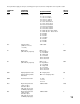
These parameters apply to each pen, assuming pen 2 is present, and are configured in each respective section.
PARAMETER PARAMETER DEFAULT
CODE DESCRIPTION SETTINGS OR RANGE SETTING
InPS Input Selection 0 - 18 1
0 = J T/C 0 to 760°C
1 = J T/C 0 to 1400°F
2 = K T/C 0 to 1360°C
3 = K T/C 0 to 2500°F
4 = T T/C -200 to 400°C
5 = T T/C -330 to 750°F
6 = R T/C 200 to 1650°C
7 = R T/C 400 to 3000°F
8 = S T/C 200 to 1650°C
9 = S T/C 400 to 3000°F
10 = RTD 100 ohm -140 to 400°C
11 = RTD 100 ohm -200 to 750°F
12 = 0-20mA
13 = 4-20mA
14 = 0-50mV
15 = 10-50mV
16 = 0-25mV
17 = 0-5VDC
18 = 1-5VDC
ICor Input Correction -999 to 999* 0
(calibrates sensor to
recorder)
A1 Output Type OFF = none OFF
(will show only if present) Hi = High Alarm
Lo = Low Alarm
HL = High Limit
LL = Low Limit
CH= Control Heat
CC= Control Cool
A2 Output Type OFF = none OFF
(will show only if present) Hi = High Alarm
Lo = Low Alarm
HL = High Limit
LL = Low Limit
CH= Control Heat
CC= Control Cool
dISP Display Input/Pen Value On = Display value On
during normal operation, OFF = Do not display value
RUN mode
dPOS Decimal Point Position 0 = nnnn 0
1 = nnn.n
2 = nn.nn
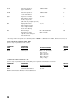
EUU Engineering Units that -9999 to 9999* 5000
equate to upper
transducer input
(will show only for Volt
or Milliamp Input types)
EUL Engineering Units that -9999 to 9999* 0
equate to lower
transducer input
(will show only for Volt
or Milliamp Input types)