
Instruction Manual


III-18 Outputs
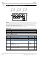
III-18.1 OUT1 and OUT2 ( process outputs 1 and 2 (No. 116, 117))
Functions OUT1 and OUT2 are used for process output OUT1 and OUT2 configuration and parameter setting. Depend-
ent of hardware, the outputs can be analog or relay outputs. Function OUT1 is firmly allocated to block number 81,
function OUT2 is firmly allocated to block number 82. They are calculated invariably in each time slot.
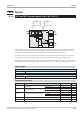
With digital input d1 used as signal source, it is switched to the digital output as specified in Mode on an instru-
ment with relay output. With continuous output, switch-over is between 0 and 20 mA as with a logic output.
Analog input x1 used as signal source is taken to the continuous output linearly between x0 and x100 dependent
of configuration. With switching output (relay or logic), switching from x0 to x100 is from 50% (hysteresis = 1%).
Inputs / outputs
Digital input:
d1
Input signal with digital signal conversion
Analog input:
x1
Input signal with analog signal conversion
Configuration parameters:
Parameter Description Values Default
Src
Signal source
Digital input d1
Digital
t
Analog input x1
Analog
Mode
Signal source action
direct/normally open
direct
t
inverse/normally closed
inverse
Type
Function of the continuous output
logic 0/20 mA
logic
0...20mA
0...20mA
t
4...20mA
4...20mA
x0
Analog input value x1 at 0%
-29 999 ... 999 999 0
x100
Analog input value x1 at 100%
-29 999 ... 999 999 100
9499-040-82711 Outputs
OUT1 and OUT2 ( process outputs 1 and 2 (No. 116, 117)) III-286
HARDWARE
SOFTWARE
Relais
Logik
0..20mA
4...20mA
d1
x1
OUT1
OUT2
OUT1
OUT2
Src
x0
x100
Type
Mode