
Instruction Manual
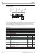


Configuration Description Values Default
Type
0...20 mA
0...20mA
t
4...20 mA
4...20mA
Transducer 0...1000 [
Pot.trans.
Fail
Fail function off
disabled
Digital output fail =1,y1 = x100
Upscale
t
Digital output fail =1,y1 = x0
Downscale
Digital output fail =1,y1 = XFail
Subst.val.
Xkorr
Measured value correction off
off
t
Measured value correction adjustable
on
x0
Physical value at 0%
only effective with standard
signals (0/4..20mA or 0/2..10V)
-29999 ... 999 999 0
x100
Physical value at 100% -29999 ... 999 999 100
XFail
Substitute value with sensor error -29999 ... 999 999 0
Tfm
Filter time constant [s]
0 ... 999 999
0,5
Input value conditioning
Before the pre-filtered (time constant ...; limiting frequency
...) analog input signals are available as digitized measure
-
ment values with physical quantity, they are subjected to ex
-
tensive input value processing.
Input circuit monitor
q
Transducers are monitored for break and short circuit.
q
Current signals Out-of-range monitoring (I > 21,5 mA) with current signals (0/4...20 mA) and short-cir -
cuit monitoring (I < 2 mA) with “life zero” signals are provided.
Sensor errors are output as digital output (fail). In case of error, statuses ‘Upscale‘, ‘Downscale‘or
‘Subst.val‘ defined in the configuration (Fail) can be used for the input circuit.
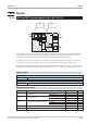
Scaling
The mA standard signals are scaled according the the physical measuring range of the transmitter ( x0, x100). With
potentiometric transducer measurements, “calibration” is according to the proven method. Bring the transducer to start
and then to end position and “calibrate” to0%or100%bykeypressure. The calibration principle corresponds to
scaling, whereby gradient and zero offset are calculated automatically by the firmware.
Filter
A 1st order filter is adjustable in addition to filtering in the analog part of each input signal.
Sampling intervals
The sampling interval for INP6 is 400ms.
Measured value correction
Measured value correction can be used for various types of measurement correction.
Pre-requisite: configuration XKorr = ein
In most cases, the relative rather than the absolute accuracy and reproducibility are of interest, e.g.:
–
measurement error compensation in a working point ( control)
–
minimization of linearity errors within a limited operating range (variable )
–
correspondence with other measuring facilities (recorders, indicators, PLCs, ...)
–
compensation of sensor, transmitter, etc. sample differences.
The measured value correction is designed both for zero offset, gain matching and for both. It corresponds to scaling
mx+b, with the difference that the KS 98-1 firmware calculates gain m and zero offset b from the defined value pairs for pro
-
cess value (x1in; x2in) and (x1out; x2out) of two reference points.
Inputs 9499-040-82711
III-283 AINP6 ( analog input 6 (No. 115))