
Instruction Manual


III-17.2 AINP3...AINP5 ( analog inputs 3...5 (No. 112...114) )
For standard signal connection
General
Functions ‘AINP3...AINP5’ are used for configuration and parameter setting of analog inputs INP3...INP5. They are
firmly allocated to block number 63...65 and are calculated in each time slot. The functions provide corrected measure -
ment values and measurement value statuses at their outputs.
For the general functions (scaling, error control, filter...) see AINP1 r Page 275
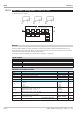
Inputs / outputs
Digital outputs:
fail
Signals an input error (short-circuit, wrong polarity, ..)
Analog outputs:
Inp1
Signal input
Parameter and configuration data
Parameter Description Values Default
x1in
Measured value correction P1, input -29999 ... 999 999 0
x1out
Measured value correction P1, output -29999 ... 999 999 0
x2in
Measured value correction P2, input -29999 ... 999 999 100
x2out
Measured value correction P2, output -29999 ... 999 999 100
Configuration Description Values Default
Type
0...20 mA 0...20mA
t
4...20 mA 4...20mA
0...10 V 0...10V
2...10 V 2...10V
Fail
Fail function off disabled
t
Digital output fail =1,y1 = x100 Upscale
Digital output fail =1,y1 = x0 Downscale
Digital output fail =1,y1 = XFail Subst.val.
Xkorr
Measured value correction off off
t
Measured value correction adjustable on
x0
Physical value at 0%
effective only with standard signals
(0/4..20mA or 0/2..10V)
-29999 ... 999 999
0
x100
Physical value at 100% -29999 ... 999 999
100
Tfm
Filter time constant [s]
0 ... 999 999 0,5
Inputs 9499-040-82711
III-281 AINP3...AINP5 ( analog inputs 3...5 (No. 112...114) )
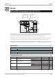
Unit
Typ
XFail
Fail
x0
x100
Tfm
x2out
Xkorr
x2in
x1out
x1in
fail
Inp6