
Instruction Manual


Manual operation
Changing between automatic and manual mode is by pressing key H. The manual mode influences only the slave
controller. The master is concerned only indirectly.
The bargraph display switches over to slave variable Y. Adjustment of the correcting variable is via the value beside
the bargraph.
+
The setpoint switchover and adjustment operations influence the master controller !
The following rules apply to the bargraph display :
w
When X or XW display is selected for the master bargraph display, the display value from the master controller is
taken over.
w
If Y display is selected, the slave bargraph value is used.
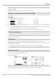
Faulty wiring of a controller cascade
If an invalid cascade circuit was built up in the engineering, e.g.
with the cascade input not connected to output Bl-no of a master
controller, the control function is not operable.
Error signalling is in the display field for the cascade:
Display: CErr
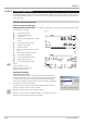
Multiple cascade
A cascade control loop can be built up from a master controller with one or several slave controllers (see Fig. 76 : Level
control example with three subordinated flow controllers). Cascade operation is from the slave controller page. Display
of the master operating page should be suppressed (hide=1).
Operator interface activation for cascade control is automatic for controllers the Casc input of which is connected with
the Bl-no output of another controller.
In the above example, 3 flow controllers operate as slave controllers for level control. All three slave controllers offer
the operator interface for level control with a separate operating page. Master tracking during manual mode of the
slave as specified for simple cascade control in the example cannot be used without detailed considerations, because
1. two further cascade branches are still intact, when one controller is in manual mode
2. it is not clear, which process value should be used for tracking, when all controllers are in manual mode
9499-040-82711
Controller applications: III-259
Fig.: 75 Faulty cascade wiring
AINP3
Inp3
fail
63
CONTR+
Weff
X
Y
XW
W
Yout1
Yout2
ParNo
Bl-no
y1
y2
cfail
off
a/m
y/y2
we/wi
pi/p
orun
ostab
oerr
xw sup
X1
X2
X3
Wext
OVC+
OVC-
Yp
Yhm
Yadd
ParNo
Casc
hide
lock
inc
dec
xf
yp f
a/m
w/w2
we/wi
pi/p
d ovc+
dovc-
track
y/y2
off
sm/hm
ostart
wstop
gr off
rsta rt
o_hide
oplock
100 ts=11
Flow.->Pu 1
PIDMA
Weff
X
Y
XW
W
Yout1
Yout2
Bl-no
y1
y2
cfail
off
a/m
y/y2
we/wi
orun
oerr
xw sup
X1
X2
X3
Wext
OVC+
OVC-
Yp
Yhm
Yadd
Casc
hide
lock
inc
dec
xf
yp f
a/m
w/w2
we/wi
track
y/y2
off
sm/hm
ostart
wstop
gr off
rsta rt
o_hide
oplock
101 ts=11
Flow.->Pu 2
CONTR
Weff
X
Y
XW
W
Yout1
Yout2
Bl-no
y1
y2
cfail
off
a/m
y/y2
we/wi
pi/p
orun
ostab
oerr
xw sup
X1
X2
X3
Wext
OVC+
OVC-
Yp
Yhm
Yadd
Casc
hide
lock
inc
dec
xf
yp f
a/m
w/w2
we/wi
pi/p
d ovc+
d ovc-
track
y/y2
off
sm/hm
ostart
wstop
gr off
rsta rt
o_hide
oplock
102 ts=11
Flow.->Pu
3
CONTR
Weff
X
Y
XW
W
Yout1
Yout2
Bl-no
y1
y2
cfail
off
a/m
y/y2
we/wi
pi/p
orun
ostab
oerr
xw sup
X1
X2
X3
Wext
OVC+
OVC-
Yp
Yhm
Yadd
Casc
hide
lock
inc
dec
xf
yp f
a/m
w/w2
we/wi
pi/p
dovc+
d ovc-
track
y/y2
off
sm/hm
ostart
wstop
gr off
rsta rt
o_hide
oplock
103 ts=11
Level
SCAL
Y1X1
117 ts=11
SCAL
Y1X1
118 ts=11
SCAL
Y1X1
119 ts=11
Slave Controlller Pump 1 [0 - 60] l/min
Slave Controller Pump 3 [0 -150] l/min
Output
Pump 1
Output
Pumpe 2
Output
Pumpe 3
Scale SP
[0-100] % = [0-60] l/min
[0-100] % = [0-150] l/min
Sollwert
[0-3] m
[0-100] % = [0-120] l/min
Level [
0
-
3
]m
Slave Controller Pump 2 [0 -120] l/min
Master Controller Level [0 - 3] m
Fig. 76 : Example of a flow-control