
Instruction Manual


I-5 Mounting
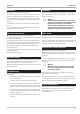
The instrument must be installed as described below. Required dimensions of the control cabinet cut-out and minimum
clearances for installation of further units are shown in the drawing.
For mounting, insert the unit into the control cabinet or cabinet door cut-out. Push the instrument module fully home
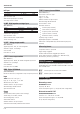
and mount it firmly by means of the locking screw. Four fixing clamps are delivered with the unit.
Ü
These clamps have to be fitted in the instrument
from the control cabinet inside: 2 at top and bot
-
tom.
*
Now, the threaded pins of the fixing clamps can
be screwed against the control cabinet from insi
-
de.
!
A rubber seal is fitted on the rear of the instrument front panel (in mounting direction).
This rubber seal must be in perfect condition, flush and cover the cut-out edges completely to ensure tightness!
cULus certification
+
For compliance with cUus certificate, the technical data at the beginning must be taken into account (see technical
data, page 12 .
Mounting 9499-040-82711
I-20 Auxiliary equipment
96 96
92
+0,8
92
?24
+0,8
1...16
min. 0°C
60°C
max.
max.
95% rel.
KS 98-1 advanced
1
2
3
4
KS 98-1 advanced
1
2
3
4
KS 98-1 advanced
1
2
3
4
96
96
160
l
Fig. 4 Mounting
¡
Ü
Fig. 5 Inserting the locking screws