
Instruction Manual
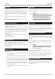


I-4.1 I/O-Modules
Can be installed on instruments with modular option C basic card.
I-4.2
Ex-factory setting
All delivered units permit operation, parameter setting and configuration via the front-panel keys.
Instruments with default setting are delivered with a test engineering which permits testing of the basic instrument in -
puts and outputs (no I/O extension) without auxiliary means.
+
This engineering is not suitable for controlling a system. For this purpose, a customer-specific engineering is required
(see versions, section: Setting)
Instruments with "setting to specification" are delivered complete with an engineering. Code no. KS
98-1-1xx-xx09x-xxx is specified on the type label.
Accessories delivered with the instrument:
Operating manual, 4 fixing clamps
I-4.3 Auxiliary equipment
Engineering Tool ET/KS 98
Simulation SIM/KS 98-1
PC-Adapter
–
Adapter cable for connecting a PC (Engineering Tool) to the front-panel interface socket of the KS 98-1.
–
Updates and Demos on the PMA- Homepage (www.pma-online.de)
9499-040-82711 Versions
I/O-Modules I-19
Singular order(separate delivery) 0
In KS 98-1 pinned to socket 1
3)
1
In KS 98-1 2pinned to socket
3)
2
In KS 98-1 3pinned to socket
3)
3
In KS 98-1 4pinned to socket
3)
4)
4
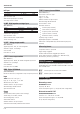
R_INP: Pt100/1000, Ni100/1000, resistor 20
TC_INP: Thermocouple, mV, 0/4...20mA 21
U_INP: -50...1500mV (z.B. Lambda-probe), 0...10V 22
U_OUT: Voltage output 30
I_OUT: Current output
31
DIDO: digitale in-/outputs 40
F_INP: Frequency-/counter inputs 41
9407 998 0 1
Module group 1
SOCKETS
2Module group
ANALOG INPUTS
ANALOG OUTPUTS
DIGITAL SIGNALS
3) Please note on your order: "mounted in KS in orderposition X"
4
)
Max. 1 current output module
98-1
Fig. 3 Table of I/O-module Versions