
Instruction Manual


PROFIBUS
Max. 4 functions DPREAD and DPWRIT can be configured (blocks 1...4 or 11...14 ). Any combination of functions is pos
-
sible. Any data can be used in the functions.
III-10.3 DPREAD ( read level1 data via PROFIBUS (No. 102) )
General
Block numbers 1...4. Any 6 analog process values (x1...x6) and any 16 digital process values (d1...d16) of the
engineerings are composed for scanning via a PROFIBUS data channel. Block number 1 provides the data for channel 1,
block number 2 provides the data for channel 2, etc.
The PROFIBUS module reads the data of two channels at intervals of 100 ms. The digital outputs indicate the
PROFIBUS status.
g
Further information on communication with PROFIBUS is given in the interface description (order no.: 9499 940 52711).
Inputs/outputs
Digital inputs:
d1 ... d8
Digital process values, which can be read via the PROFIBUS (status byte 1)
d9 ... d16
Digitale process values, which can be read via the PROFIBUS (status byte 2)
Digital outputs:
b-err
PROFIBUS status: 1 = bus access not successful
p-err
PROFIBUS status: 1 = faulty parameter setting
c-err
PROFIBUS status: 1 = faulty configuration
d-err
PROFIBUS status:1=nodata communication
Analog inputs:
x1 ... x6
Analog process values, which can be read via the PROFIBUS
9499-040-82711 Communication
DPREAD ( read level1 data via PROFIBUS (No. 102) ) III-171
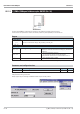
Interface
Statusbyte1
(0)
(1)
(2)
(3)
(4)
(5)
(6)
(7)
76543210
d8
d1
...
Statusbyte2
76543210
d16
d9
...
x1
.
.
.
.
.
x6
b-err
p-err
c-err
d-err