
Instruction Manual


III-8.6 ALARM ( alarm processing (No. 45) )
x1 is checked for a lower and an upper alarm value. Additionally, digital alarm input fail can be used. Configura
-
tion parameter Fnc can be used to select which signal shall be monitored (x1, x1 + fail or fail).
With input stop = 1, alarms (fail and x1) are suppressed. After removal of this signal, suppression lasts, until
the monitored value is again within the limits. This can be used e.g. for suppressing an alarm message with change.
During value change at the exit xw
sup a pulse with the length of a
scanning cycle Ts is sent.
Inputs/outputs
Digital inputs
fail
Digital alarm signal e.g. fail signal of AINP
stop
stop = 1, alarms (fail and x1) are suppressed. After stop returned to 0, suppression lasts, until the
monitored value is again within the limits.
Analog input
x1
Input variable to be limited
Digital output
alarm
Alarm status:0=noalarm; 1= alarm
Configuration parameter:
Parameter Description Range Default
Fnc
Alarm function
only x1 is monitored
Mes.val.X1
t
x1 and fail are monitored
X1 + fail
only fail is monitored
fail
Parameters:
Parameter Description Range Default
LimL
lower limit for the alarm
-29 999 ... 999 999 -10
LimH
upper limit for the alarm
-29 999 ... 999 999 10
Lxsd
Switching hysteresis Xsd
0 ... 999 999 10
Limit value signalling and limiting 9499-040-82711
III-153 ALARM ( alarm processing (No. 45) )
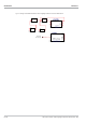
stop
fail
LimL
LimH
Xsd
x1
Fnc
alarm
Fig. 16 Alarm suppression with change