
Instruction Manual


III-8.2 ALLV ( alarm and limiting with variable limits (No. 41))
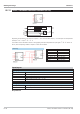
Signal limiting:
Analog input H1determines the maximum limiting, L1 determines the minimum limiting. y1 is limited to the range
between L1 and H1 (L1 ß y1 ß H1).
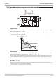
As both H1 and L1 come from analog inputs, H1 can be smaller than L1. In this case, H1 is assigned a higher pri-
ority. This means that signal y1 is ß H1!
Limit signaller:
The limit signaller has 2 low and high alarms (L1, L2, H1 and H2). The variable to be monitored can be se
-
lected with configuration parameter Select (x1, dx1/dt, x1 - x0).
The limit values are freely adjustable via the analog inputs H1 and L1 and have an adjustable hysteresis of ? 0.
The smallest separation between a minimum and a maximum limit value is 0. With an alarm triggered, the relevant
output (L1, L2, H1 and H2) is logic “1".
D alarm (dx1/dt)
Value x1(t-1) measured one sampling interval before is subtracted from instantaneous value x1(t). This difference is di
-
vided by calculation cycle time Tr (100, 200, 400, 800ms).
Thus input variable x1 can be monitored for rate of change.
9499-040-82711 Limit value signalling and limiting
ALLV ( alarm and limiting with variable limits (No. 41)) III-148
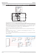
Select
H2
L2
Y1
h1
h2
l1
l2
Xsd
X0
X1
H1
L1
_
H2
L1
H1
Fig. 12 Limiting at H1 < L1