
Instruction Manual

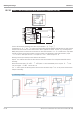


Alarm with offset (x1-x0):
x1 can be shifted by means of x0. This corresponds to the offset of the adjusted alarm limits (L1, L2, H1 and H2) in par
-
allel to the x-axis.
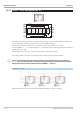
Inputs/outputs
Analog input
x1
Input value to be monitored
Digital outputs
L1
Low alarm 1 - becomes logic 1, if x1 < L1
L2
Low alarm 2 - becomes logic 1, if x1 < L2
H1
High alarm 1 - becomes logic 1, if x1 <H1
H2
High alarm 2 - becomes logic 1, if x1 <H2
Analog output
y1
Calculated and limited input signal
x1
.
Configuration parameter:
Parameter Description Range Default
Select
Selection of the variable to be monitored
x1
x1
t
D alarm
dx1/dt
Alarm with offset
x1-x0
Parameters:
Parameter Description Range Default
H1
High alarm 1 -29 999 ... 999 999
9999
H2
High alarm 2 -29 999 ... 999 999
9999
L1
Low alarm 1 -29 999 ... 999 999
-9999
L2
Low alarm 2 -29 999 ... 999 999
-9999
x0
Offset x0 -29 999 ... 999 999
0
Xsd
Switching hysteresis 0 ... 999 999
1
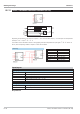
Limit value signalling and limiting 9499-040-82711
III-147 ALLP ( alarm and limiting with fixed limits(No. 40))
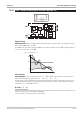
Xsd
min
max
L1, L2
H1, H2
x
Fig. 10 Switching hysteresis and alarm limits:
+x
0
-x
0
x
y
Fig. 11 Offset of the alarm limits