
Instruction Manual


Connections
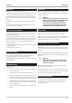
Depending on version and selected options, the following inputs
and outputs are available:
DI DO AI AO
4 relays
or
2 relays
+
2AO
di1*
di2*
OUT1
OUT2
OUT4
OUT5
INP1
INP5
INP6
–
di1*
di2*
OUT4
OUT5
INP1
INP5
INP6
OUT1
OUT2
OPTION B
di3
di4
di5
di6
di7
do1
do2
do3
do4
––
OPTION C*
or
di8
di9
di10
di11
di12
do5
do6
INP3
INP4
OUT3
modular
OPTION C*
Depending on module type
*
Not available with option CAN!
Inputs
Universal input INP1
Limiting frequency: fg=1Hz,Measurementcycle: 200 ms
Thermocouples
according to DIN IEC 584
Type Range Error Resolution
L –200...900°C £ 2K 0,05 K
J –200...900°C £ 2 K 0,05 K
K –200...1350°C £ 2 K 0,072 K
N –200...1300°C £ 2 K 0,08 K
S –50...1760°C £ 3 K 0,275 K
R –50...1760°C £ 3 K 0,244 K
B
1)
(25)400...1820°C £ 3 K 0,132 K
T –200.. .400°C £ 2 K 0,056 K
W(C)
2)
0...2300°C £ 2 K 0,18 K
E –200... 900°C £ 2 K 0,038 K
*
1 ) from 400 °C
*
2 ) W5Re/W26Re
With linearization (temperature-linear in °C or °F)
Input resistance: ³ 1MW
Cold-junction compensation (CJC): built in
Input circuit monitor:
Current through sensor: £ 1
m
A
Reverse-polarity monitor is triggered at 10 °C below span start.
Additional error of internal CJC
£ 0.5 K per 10 K terminal temperature External temperature
selectable: 0...60 °C or 32...140 °F
Resistance thermometer
Pt 100 to DIN IEC 751, and temperature difference2xPt100
Range Error Resolution
–200.0...250.0 °C £ 0.5 K 0.024 K
–200.0...850.0 °C £ 1.0 K 0.05 K
2 x –200.0...250.0 °C £ 0.5 K 0.024 K
2 x –200.0...250.0 °C £ 0.1 K 0.05 K
Linearization in °C or ° F
Two wire connection with compensation or three-wire connection
without.
Two-wire connection with lead resistance adjustment.
Lead resistance: £ 30 W per lead
Sensor current: £ 1mA
Input circuit monitoring for sensor/lead break, and lead short circuit.
Potentiometric transducer
R
total
incl. 2 x R
L
Error Resolution
0...500 W£0.1 % £ 0.02 W
Resistance-linear
Sensor current: £ 1mA
Matching/scaling with sensor connected.
Input circuit monitoring for sensor/lead break, and lead short circuit.
Resistance input
Range Error Resolution
0...250 W£0.25 W < 0.01 W
0...500 W£0.5 W < 0.02 W
Direct current 0/4...20mA
Range Error Resolution
0/4...20 mA £ 0.1 % £ 0.8 mA
Input resistance: 50 W
Input circuit monitor with 4...20mA: triggered when I £ 2mA
Direct voltage
Range Error Resolution
0/2...10 V £ 0.1 % £ 0.4 mV
Input resistance ³ 100 kW
9499-040-82711 Technical data
I-13