
Instruction Manual
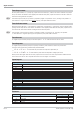


Analog inputs
x1
Input variable to be integrated
Preset
External preset value
Digital outputs
max
= 1 exceeded with max. limiting
min
= 1 exceeded with min. limiting
Analog output
y1
Integrator output after elapse of integration
tnts=×
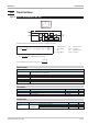
Parameters:
Parameter Description Range Default
T
Time constant in s 0.1...999 999 60
x0
Constant -29 999...999 999 0
y0
Preset value -29999...999 999 0
Min
Min. limiting -29999...999 999 1
Max
Max. limiting -29999...999 999 0
Mode
Source of preset = Para y0 0 0
Source of preset = InpPreset 1
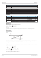
Ramp function:
With constant input x1+x0, the applicable formulas are
yt yt n
ts
T
xx10 10() ( ) ( )=+××+
tnts=×
t is the time required by the integrator for changing output y1 linearly by value x1 + x0 after integration start.
Ramp response:
The function has a ‘memory’. This means: after power-on, it continues operating with values y1, z1 and z2, which ex
-
isted at power-on, provided that the RAM data are still available.
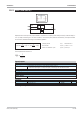
Example: Which is the value of output variable y after t=20s with a time constant of 100s, if a constant of x1 = 10 Volt
is preset. Sampling interval ts is 100ms.
n
t
t
s
= n
s
s
s==
20
01
200
,
yafters=+ × × =0 200
01
100
10 2 20
,
__
This results in a gradient of 2V/20s or 0.1Volt /1s.
Time functions 9499-040-82711
III-127 INTE (integrator (No. 51))
Fig. 6