
Instruction Manual


Inputs/outputs
Digital input
d1
This signal is output with a delay at output z1 and negated at output not z1.
Analog inputs
T1
Delay time T1 [s], by which the positive signal of d1 is delayed, when Mode = Inputs.
T2
Delay time T2 [s],by which the negative signal of d2 is delayed, when Mode = Inputs.
Digital outputs
z1
Delayed input signal d1.
not z1
Inverted delayed input signal d1.
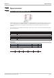
Configuration:
Configuration Description Range Default
Mode
Source of delay times
parameters T1 and T2
Parameters
r
Inputs T1 and T2
Inputs
The pulse duration accuracy is dependent of the time group to which the function is assigned.
It is an integer multiple of the sampling interval adjusted for this block (100, 200, 400, 800ms).
Example:
T1 = 0,7s with assignment to
- sample time 100ms means, delay time of the positive flank is 0,7s.
- sample time 200ms means, delay time of the positive flank is 0,8s.
- sample time 400ms means, delay time of the positive flank is 1,2s.
- sample time 800ms means, delay time of the positive flank is 1,6s.
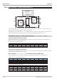
Example with different delay time T1 and T2
Logic functions 9499-040-82711
III-113 TIME1 (timer (No. 69))
Input
Output
Output
Output
Output
Output
Output
d1
z1
z1
z1
z1
z1
z1
T1 = 1
T2 = 1
T1 = 1
T2 = 2
T1 = 1
T2 = 3
T1 = 1
T2 = 4
T1 = 2
T2 = 1
T1 = 3
T2 = 1
T1
T1
T1
T2 T2T1
T2 T2T1
T1
T2 T2
T1T1
T2 T2
T1 T2 T1
T1
T2
T1
T2 T2
Fig. 111