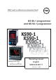
PMA Prozeß- und Maschinen-Automation GmbH KS 90-1 programmer and KS 92-1 programmer KS90-1 KS90-1 Operating manual advanced line English 9499-040-66111 Valid from: 8499
û BlueControl More efficiency in engineering, more overview in operating: The projecting environment for the BluePort controllers n o ! s ON ate I pd de T N U e. E and nlin D T ATrsion ma-o A-C e .p PM V ni ww r on i M w o Description of symbols in the text: on the device: g General information a Follow the operating instructions a General warning l Attention: ESD-sensitive devices © PMA Prozeß- und Maschinen-Automation GmbH Printed in Germany All rights reserved.
Content 1. 2. Mounting . . . . . . . . . . . . . . . . . . . . . . . . . . . . . 5 Electrical connections . . . . . . . . . . . . . . . . . . . . . . . 6 2.1 2.2 3. Connecting diagram . . . . . . . . . . . . . . . . . . . . . . . . . . 6 Terminal connection . . . . . . . . . . . . . . . . . . . . . . . . . . 7 Operation. . . . . . . . . . . . . . . . . . . . . . . . . . . . . 11 3.1 3.2 3.3 3.4 3.5 Front view . . . . . . . . . . . . . Behaviour after power-on . . . . . Operating level . . . . . . . . .
.4.6 4.4.7 4.4.8 5. Parameter setting level . . . . . . . . . . . . . . . . . . . . . 52 5.1 5.2 5.3 Parameter survey . . . . . . . . . . . . . . . . . . . . . . . . . . 52 Parameters . . . . . . . . . . . . . . . . . . . . . . . . . . . . . . 53 Input scaling . . . . . . . . . . . . . . . . . . . . . . . . . . . . . . 55 5.3.1 5.3.2 6. 7. Parameter survey . . . . . . . . . . . . . . . . . . . . . . . . . . 59 Parameters . . . . . . . . . . . . . . . . . . . . . . . . . . . . .
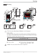
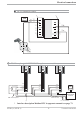
Mounting 1 Mounting °C °F para func Ada Err è 4 921.2 F Loc locking switch FF C SP.E Ada Err (1.77" +0.02) SP.E SP.2 o para func SP.2 45 1200 +0,6 3 run 96 (3.78") 1199 2 920.1 44 SP.E 3 SP.2 run 2 1 96 1 +0,8 (4 18 (3.62" +0.03) 1 ") 5 .6 (0 1. .0 .1 4. 0 .0 .4 ") 10 ( 92 ") 4 0. 92 +0,8 92 +0,8 min.48 (1.89") KS 92-1 advanced 96 KS 92-1 advanced 8 11 10 KS 90-1 advanced 48 (1.89") max. 60°C min. 0°C max. 95% rel.
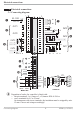
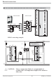
Electrical connections 2 Electrical connections 2.1 Connecting diagram 90...250V 24 V UC 1 2 3 4 5 6 OUT1 2 OUT3 3 10 11 12 V KS90-1.4 -... KS90-1.5 -... OUT4 13 14 15 V KS90-1.2 -... 5 7 di2 4 5 6 7 8 9 10 11 12 13 14 15 (16) 17 7 8 9 OUT2 di1 1 2 3 Option 1 g HC mA f mA 0% 100% INP2 5 INP3 6 KS90-1..-.1...
Electrical connections 2.2 Terminal connection Power supply connection 1 See chapter 11 "Technical data" Connection of outputs OUT1/2 2 Relay outputs (250V/2A), potential-free changeover contact Connection of outputs OUT3/4 3 2 OUT1/2 heating/cooling 1 2 L relay (250V/2A), potential-free changeover contact universal output b current (0/4...20mA) c voltage (0/2...10V) d transmitter supply e logic (0..20mA / 0..
Electrical connections Connection of output U 9 (option) T Supply voltage connection for external energization Connection of outputs OUT5/6 0 (option) Digital outputs (opto-coupler), galvanic isolated, common positive control voltage, output rating: 18...
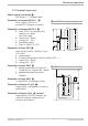
Electrical connections 3 OUT3 transmitter supply 13V 22mA - 10 + 11 11 12 12 13 14 15 13 + 14 15 - (16) 17 1 3 K 2 10 11 12 1 13 13 14 14 1 15 DATA A 11 12 13 14 1 15 15 (2) (2) 3 3 4 4 4 5 5 5 6 6 6 7 7 7 8 8 8 9 9 9 10 10 10 12 15 (16) RT 10 3 11 RGND 17 11 12 RGND 13 14 DATA B 11 (2) 13 RT = 120...
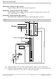
Electrical connections 3 OUT3 as logic output with solid-state relay (series and parallel connection) Series connection Parallel connection SSR _ Imax=22mA 4V + Imax=22mA SSR _ SSR _ 10 11 12V + 4V 12 SSR _ 12V + Logic 10 11 12 SSR _ 4V + + KS90-1 connecting example: L1 L2 fuse 1 TB 40-1 Temperature limiter Standard version (3 relays): TB40-100-0000E-000 r other versions on request fuse fuse KS90-1 7 8 9 10 11 1 1 2 3 3 4 5 6 Logik 12 13 14 15 4 5 6 7 8 9 10 11 12 13 14 2
Operation 3 Operation 3.1 Front view 1199 4 5 6 7 8 °C °F p para f func A Ada Err 1200 01 OFF 1 2 3 9 SP.E SP.2 run $§"!0 ( / F ) % 1 2 3 5 6 7 8 % & / ( ) 2 3 4 920.1 o para func 4 Ada Err C 921.2 01 OFF 9 $§"!0 F & ) 1 3 5 7 9 ! § $ 1 SP.E 4 SP.2 3 SP.E 2 Srun SP.2 1 ( / & % Statuses of switching outputs OuT.1...
Operation 3.2 Behaviour after power-on After supply voltage switch-on, the unit starts with the operating level. The unit is in the condition which was active before power-off. If KS 90-1 was in manual mode at supply voltage switch-off, the controller will re-start with the last output value in manual mode at power-on. 3.3 Operating level The content of the extended operating level is determined by means of BlueControl (engineering tool).
Operation 3.4 Error list / Maintenance manager With one or several errors, the extended operating level always starts with the error list. Signalling an actual entry in the error list (alarm, error) is done by the Err LED in the display. To reach the error list press Ù twice. Err LED status blinks(status 2) lit(status 1) off(status 0) Signification Alarm due to existing error Error removed, alarm not acknowledged No error, all alarm entries deleted 1199 °C °F para func Ada Err 1200 SP.E SP.
Operation Name Description Reason - Current flow in heating circuit short circuit (SSR) with controller off - SSR defective Control loop alarm - Input signal defective or not (LOOP) connected correctly - Output not connected correctly Self-tuning heating - See Self-tuning heating error alarm status (ADAH) Self-tuning heating - See Self-tuning cooling error alarm cooling status (ADAC) stored limit alarm 1 - adjusted limit value 1 exceeded stored limit alarm 2 - adjusted limit value 2 exceeded stored limit
Operation Self-tuning heating ( ADA.H) and cooling ( ADA.C) error status: Error status 0 3 4 5 6 7 8 9 Description No error Faulty control action No response of process variable Low reversal point Danger of exceeded set-point (parameter determined) Output step change too small (dy > 5%) Set-point reserve too small Behaviour Re-configure controller (inverse i direct) The control loop is perhaps not closed: check sensor, connections and process Increase ( ADA.H) max. output limiting Y.Hi or decrease ( ADA.
Operation 3.5.1 Preparation for self-tuning Adjust the controller measuring range as control range limits. Set values rnG.L and rnG.H to the limits of subsequent control. (Configuration r Controllerrlower and upper control range limits) ConFrCntrr rnG.L and rnG.H w Determine which parameter set shall be optimized. The instantaneously effective parameter set is optimized. r Activate the relevant parameter set (1 or 2). w Determine which parameter set shall be optimized (see tables above).
Operation 3.5.
Operation 3.5.6 Optimization at the set-point Conditions: w A sufficient set-point reserve is not provided at self-tuning start (see page 17). w tunE is 0 or 1 w With Strt = 1 configured and detection of a process value oscillation by more than ± 0,5% of (rnG.H - rnG.L) by the controller, the control parameters are preset for process stabilization and the controller realizes an optimization at the set-point (see figure “Optimization at the set-point”).
Operation 3.5.7 Optimization at the set-point for 3-point stepping controller With 3-point stepping controllers, the pulse attempt can be made with or without position feedback. Unless feedback is provided, the controller calculates the motor actuator position internally by varying an integrator with the adjusted actuator travel time. For this reason, precise entry of the actuator travel time (tt), as time between stops is highly important.
Operation 3.5.8 Self-tuning start Start condition: w For process evaluation, a stable condition is required. Therefore, the controller waits until the process has reached a stable condition after self-tuning start. The rest condition is considered being reached, when the process value oscillation is smaller than ± 0,5% of (rnG.H - rnG.L). w For self-tuning start after start-up, a 10% difference from (SP.LO ... SP.Hi) is required. g Self-tuning start can be blocked via BlueControl® (engineering tool) ( P.
Operation 3.5.9 Self-tuning cancellation By the operator: Self-tuning can always be cancelled by the operator. For this, press Ù and È key simultaneously.With controller switch-over to manual mode after self-tuning start, self-tuning is cancelled. When self-tuning is cancelled, the controller will continue operating using the old parameter values. By the controller: If the Err LED starts blinking whilst self-tuning is running, successful self-tuning is prevented due to the control conditions.
Operation 3.5.11 Examples for self-tuning attempts (controller inverse, heating or heating/cooling) Start: heating power switched on Heating power Y is switched off (1). When the change of process value X was constant during one minute (2), the power is switched on (3). At the reversal point, the self-tuning attempt is finished and the new parameter are used for controlling to set-point W. Start: heating power switched off The controller waits 1,5 minutes (1). Heating power Y is switched on (2).
Operation 3.6 Manual self-tuning The optimization aid should be used with units on which the control parameters shall be set without self-tuning. For this, the response of process variable x after a step change of correcting variable y can be used. Frequently, plotting the complete response curve (0 to 100%) is not possible, because the process must be kept within defined limits.
Operation Parameter adjustment effects Parameter Control Pb1 higher increased damping lower reduced damping td1 higher reduced damping lower increased damping ti1 higher increased damping lower reduced damping Line-out of disturbances Start-up behaviour slower line-out slower reduction of duty cycle faster line-out faster reduction of duty cycle faster response to disturbances faster reduction of duty cycle slower response to disturbances slower reduction of duty cycle slower line-out slower
Operation 3.8 Alarm handling Max. three alarms can be configured and assigned to the individual outputs. Generally, outputs OuT.1... OuT.6 can be used each for alarm signalling. If more than one signal is linked to one output the signals are OR linked. Each of the 3 limit values Lim.1 … Lim.3 has 2 trigger points H.x (Max) and L.x (Min), which can be switched off individually (parameter = “OFF”). Switching difference HYS.x and delay dEl.x of each limit value is adjustable.
Operation g g The variable to be monitored can be selected seperately for each alarm via configuration The following variables can be monitored: w process value w control deviation xw (process value - set-point) w control deviation xw + suppression after start-up or set-point change After switching on or set-point changing, the alarm output is suppressed, until the process value is within the limits for the first time. At the latest after expiration of time 10 ti1, the alarm is activated.
Operation 3.9 Operating structure After supply voltage switch-on, the controller starts with the operating levels. The controller status is as before power off. 1199 Ù 1200 1199 para ProG 3 Sek. Ù PASS 1199 para Ù PArA Ì PASS 1199 para ConF Ì Ù 1199 CAL Ì PASS Ù 1199 End g PArA - level: At PArA - level, the right decimal point of the bottom display line is lit continuously. g ConF - level: At ConF - level, the right decimal point of bottom display line blinks.
Configuration level 4 Configuration level rnG.L rnG.H CYCL tunE Strt Configuration survey HC.SC P.End FAi.1 FAi.2 FAi.3 Othr Display, operation, interface LOGI Digital inpu ts LP.AL HC.AL HC.SC P.End FAi.1 FAi.2 FAi.3 OuT.0 Out.1 O.Src Out.6 Output 6 LP.AL HC.AL HC.SC P.End FAi.1 FAi.2 FAi.3 OuT.0 Out.1 O.Src LP.AL HC.AL See output 1 O.tYP O.Act Y.1 Y.2 Lim.1 Lim.2 Lim.3 Out.5 Output 5 O.tYP O.Act Y.1 Y.2 Lim.1 Lim.2 Lim.3 See output 1 Src.1 Y.1 Fnc.2 Y.2 Src.2 Lim.1 Fnc.3 Lim.2 Src.3 Lim.
Configuration level 4.1 Configuration parameters q Cntr Name SP.Fn C.tYP C.Fnc C.dif mAn C.Act FAIL rnG.L rnG.H Value range Description Default 0 Basic configuration of setpoint processing 0 set-point controller can be switched over to external set-point (-> LOGI/ SP.E) 8 standard controller with external offset (SP.E) 9 Programmer with external offset (SP.
Configuration level Name Value range Description Default 0 Characteristic for 2-point- and 3-point-controllers 0 standard 3 with constant cycle 0 tunE Auto-tuning at start-up 0 At start-up with step attempt, at set-point with impulse attempt 1 At start-up and at set-point with impulse attempt. Setting for fast controlled systems (e.g.
Configuration level Name Value range Description Default 20 Pt100 (-200.0 ... 100,0 °C) ( -200,0 ... 150,0°C with reduced lead resistance: measuring resistance + lead resistance ß160 [ ) 21 Pt100 (-200.0 ... 850,0 °C) 22 Pt1000 (-200.0 ... 850.0 °C) 23 special 0...4500 Ohm (preset to KTY11-6) 24 special 0...450 Ohm 30 0...20mA / 4...20mA 1 40 0...10V / 2...10V 1 41 special -2,5...115 mV 1 42 special -25...1150 mV 1 50 potentiometer 0...160 Ohm 1 51 potentiometer 0...450 Ohm 1 52 potentiometer 0...
Configuration level Name Value range Description Default 30 Sensor type selection 30 0...20mA / 4...20mA 1 31 0...50mA AC 1 50 Potentiometer ( 0...160 Ohm) 1 51 Potentiometer ( 0...450 Ohm) 1 52 Potentiometer ( 0...1600 Ohm) 1 53 Potentiometer ( 0...4500 Ohm) 1 0 Corr Measured value correction / scaling 0 Without scaling 1 Offset correction (offset entry is at controller CALlevel) 2 2-point correction ( calibration is at controller CALlevel) 3 Scaling (at PArA level) OFF In.F -1999...
Configuration level Name Value range Description Default 20 Pt100 (-200.0 ... 100,0 °C) ( -200,0 ... 150,0°C with reduced lead resistance: measuring resistance + lead resistance ß160 [ ) 21 Pt100 (-200.0 ... 850,0 °C) 22 Pt1000 (-200.0 ... 850.0 °C) 23 special 0...4500 Ohm (preset to KTY11-6) 24 special 0...450 Ohm 30 0...20mA / 4...20mA 1 41 special -2,5...115 mV 1 42 special -25...115 0mV 1 50 potentiometer 0...160 Ohm 1 51 potentiometer 0...450 Ohm 1 52 potentiometer 0...1600 Ohm 1 53 potentiometer 0..
Configuration level Name Value range Description Default 3 measured value INP1 4 measured value INP2 5 measured value INP3 6 effective setpoint Weff 7 correcting variable y (controller output) 8 control variable deviation xw (actual value - internal setpoint) = deviation alarm to internal setpoint 9 difference x1 - x2 (utilizable e.g.
Configuration level Name Value range Description INP1/ INP2 / INP3 error signal 0 not active 1 active PROFIBUS error 0 not active 1 active: Profibus trouble, no communication with this instrument. Prg.1 Programmer Control track 1/2/3/4 0 not active Prg.2 1 active Prg.3 FAi.1 FAi.2 FAi.3 dP.Er Prg.4 CAll 0 1 fOut 0 1 Operator call not active active Forcing OUT1 (only visible with BlueControl!) No forcing Forcing via serial interface Default 0 0 0 Configuration parameters Out.2 as Out.
Configuration level Name FAi.1 FAi.2 FAi.3 Prg.1 Prg.2 Prg.3 Prg.4 CAll Value range Description INP1/2/3 error (only visible when O.TYP=0) 0 not active 1 active Programmer Control track 1/2/3/4 0 not active 1 active Default 0 0 0 Operator call 0 not active 1 active Out.0 -1999...9999 Scaling of the analog output for 0% (0/4mA or 0/2V, only visible when O.TYP=1..5) Out.1 -1999...9999 Scaling of the analog output for 100% (20mA or 10V, only visible when O.TYP=1..5) O.
Configuration level Name SP.2 SP.E Y2 Y.E mAn C.oFF m.Loc KS 90-1p / KS 92-1p Value range Description Switching to second setpoint SP.2 0 no function (switch-over via interface is possible) 2 DI1 switches 3 DI2 switches (only visible with OPTION) 4 DI3 switches (only visible with OPTION) 5 è - key switches Switching to external setpoint SP.
Configuration level Name Err.r Pid.2 P.run P.off I.Chg di.
Configuration level Name PrtY dP.Ad bc.uP dELY Unit dP LED dISP C.dEl dP.AD bc.up FrEq MAst CycL AdrO AdrU Numb ICof Value range Description Default 1 Data parity on the interface (only visible with OPTION) 0 no parity (2 stop bits) 1 even parity 2 odd parity 3 no parity (1 stopbit) 0...126 PROFIBUS address 126 Back-up controller (see page ) 0 No back-up controller 1 Back-up controller Delete line, order was faulty 0...
Configuration level Name IAda IExo ILat PTmp pPre pRun pSwi pCom Pass IPar ICnf ICal CDis3 TDis3 T.dis3 T.InF1 T.InF2 Value range Description Block auto tuning (only visible with BlueControl!) 0 Released 1 Blocked Block extended operating level (only visible with BlueControl!) 0 Released 1 Blocked Suppression error storage (visible only with BlueControl®!) 0 No: error message remain in the error list until acknowledgement.
Configuration level Lin (only visible with BlueControlâ Name Value range Description Default Lin Linearization for inputs INP1 or INP3 Access to this table is always with selection special thermocouple for InP.1 or InP.3or with setting S.Lin = 1: special linearization for linearization. Default: KTY 11-6 (0...4,5 kOhm) 0 U.LinT Unit of linearizationtable 0 No unit 1 In Celsius [°C] 2 In Fahrenheit [°C] 1036 In.1 -999.0..
Configuration level 4.2 Set-point processing The set-point processing structure is shown in the following picture: 1199 °C °F para func Ada Err 1200 Xeff Internal set-point SP.E SP.2 Ü Limiting Programmer 0 8 + Ü + 1 9 * SP.Hi Ramp SP.Lo Ö external SP.E set-point - LED 2nd SP.2 set-point Index: Ü : int/ext-setpoint switching * : configuration SP.Fn Ö : SP / SP.2 switching Effektive r.
Configuration level 4.3 KS90-1 cooling functions With these controllers, configuration parameter CYCL (ConF/ Cntr/ CYCL) can be used for matching the cycle time of 2-point and 3-point controllers. Selection between “standard” (CyCl= 0) and “with constant cycle” (CyCl= 3) is possible. 4.3.1 Standard ( CyCl= 0 ) The adjusted cycle times t1 and t2 are valid for 50% or -50% correcting variable.
Configuration level 4.4 Configuration examples 4.4.1 On-Off controller / Signaller (inverse) InL.1 SP.LO SP SP.Hi InH.1 InP.1Ê 100% SH Out.1Â 0% ConF/Cntr: SP.Fn = 0 C.Fnc = 0 C.Act = 0 ConF/Out.1: O.Act Y.1 PArA/Cntr: Hysl PArA/Cntr: HysH PArA/SEtP: SP.LO SP.Hi g set-point controller signaller with one output inverse action (e.g. Heating applications) =0 action Out.1 direct =1 control output Y1 active = 0...9999 switching difference (below set-point) = 0...
Configuration level 4.4.2 2-point controller (inverse) InL.1 SP.LO InP.1Ê SP SP.Hi InH.1 PB1 100% Out.1Â 0% ConF / Cntr: SP.Fn C.Fnc C.Act ConF / Out.1: O.Act Y.1 Pb1 PArA / Cntr: PArA / SEtP: g ti1 td1 t1 SP.LO SP.Hi = 0 = 1 = 0 set-point controller 2-point controller (PID) inverse action (e.g. heating applications) = 0 action Out.1 direct = 1 control output Y1 active = 1...9999 proportional band 1 (heating) in units of phys. quantity (e.g. °C) = 0,1...
Configuration level 4.4.3 3-point controller (relay & relay) InL.1 SP.LO InP.1Ê SP PB1 100% SP.Hi InH.1 PB2 Out.1Â Out.2Â 0% 0% ConF / Cntr: SP.Fn C.Fnc C.Act ConF / Out.1: O.Act Y.1 Y.2 O.Act Y.1 Y.2 Pb1 ConF / Out.2: PArA / Cntr: Pb2 PArA / SEtP: Configuration examples 100% ti1 ti2 td1 td2 t1 t2 SH SP.LO SP.Hi = 0 = 3 = 0 set-point controller 3-point controller (2xPID) action inverse (e.g. heating applications) = 0 action Out.
Configuration level 4.4.4 3-point stepping controller (relay & relay) InL.1 SP.LO InP.1Ê SP SP.Hi InH.1 PB1 100% 100% SH Out.1Â Out.2Â 0% ConF / Cntr: SP.Fn C.Fnc C.Act = 0 = 4 = 0 ConF / Out.1: O.Act Y.1 Y.2 O.Act Y.1 Y.2 Pb1 = = = = = = = ti1 td1 t1 SH tP tt SP.LO SP.Hi = = = = = = = = ConF / Out.2: PArA / Cntr: PArA / SEtP: g 0% set-point controller 3-point stepping controller inverse action (e.g. heating applications) 0 action Out.
Configuration level 4.4.5 Continuous controller (inverse) SP.LO InL.1 InP.1Ê SP SP.Hi InH.1 PB1 20 mA Out.3Â 0/4 mA ConF / Cntr: SP.Fn C.Fnc C.Act = 0 = 1 = 0 ConF / Out.3: O.tYP Out.0 Out.1 Pb1 = = = = 1/2 -1999...9999 -1999...9999 1...9999 ti1 td1 t1 SP.LO SP.Hi = = = = = 0,1...9999 0,1...9999 0,4...9999 -1999...9999 -1999...9999 PArA / Cntr: PArA / SEtP: g g set-point controller continuous controller (PID) inverse action (e.g. heating applications) Out.
Configuration level 4.4.6 D - Y - Off controller / 2-point controller with pre-contact InL.1 SP.LO SP InP.1Ê SP.Hi InH.1 PB1 100% Out.1Â 0% Out.2Â SH ConF / Cntr: SP.Fn C.Fnc C.Act ConF / Out.1: O.Act Y.1 Y.2 O.Act Y.1 Y.2 Pb1 ConF / Out.2: PArA / Cntr: ti1 td1 t1 SH d.SP PArA / SEtP: KS 90-1p / KS 92-1p SP.LO SP.Hi d.SP = 0 = 2 = 0 set-point controller D -Y-Off controller inverse action (e.g. heating applications) = 0 action Out.
Configuration level 4.4.7 Continuous controller with integrated positioner ( Cntr/ C.Fnc = 6 ) ( Cntr/ C.Fnc = 6 ) SP W INP.1 X OUT.4 Ycontinuous Ypid Master controller W OUT.1 Y.1 INP.2 X M Y.2 OUT.2 Position controller Basically, this controller function is a cascade. A slave controller with three-point stepping behaviour working with position feedback Yp as process value (INP2 or INP3) is added to a continuous controller. ConF / Cntr SP.Fn = 0 setpoint controller C.
Configuration level 4.4.8 Measured value output phys. quantity Out.1 mA / V phys. quantity Out.0 20mA 10V 0/4mA 0/2V 90...250VAC 24VUC } NL 1 2 1 2 3 3 4 5 6 7 8 9 OUT3 OUT4 10 11 12 U 13 14 15 4 5 6 7 8 9 10 11 12 13 14 U 15 (16) INP1 17 + ConF / Out.3 / 4: O.tYP = = = = Out.0 = 1 2 3 4 -1999...9999 Out.1 = -1999...9999 O.Src = 3 KS 90-1p / KS 92-1p 51 Out.3/ 4 0...20mA continuous Out.3/ 4 4...20mA continuous Out.3/ 4 0...10V continuous Out.3/ 4 2...10V continuous scaling Out.
Parameter setting level 5 Parameter setting level 5.1 Parameter survey InL.1 OuL.1 InH.1 OuH.1 tF.1 E.tc InL.3 OuL.3 InH.3 OuH.3 tF.3 End Inl.2 OuL.2 InH.2 OuH.2 tF.2 Lim Limit value functions Input 3 Input 2 Input 1 InP.1 SEtP Set-point and process value SP.Lo SP.Hi SP.2 r.SP InP.3 Pb12 Pb22 ti12 ti22 td12 td22 InP.2 Pb1 Pb2 ti1 ti2 td1 td2 t1 t2 SH Hys.l Hys.H d.SP tP tt Y.Lo Y.Hi Y2 Y0 Ym.H L.Ym E.H2O t.on t.off FH2 oFFS tEmp PAr.2 2.
Parameter setting level 5.2 Parameters q Cntr Name Pb1 Pb2 ti1 ti2 td1 td2 t1 t2 SH Hys.l Hys.H d.SP tP tt Y.Lo Y.Hi Y2 Y.0 Ym.H L.Ym E.H2O t.on t.oFF F.H2O oFFS Valuerange Description Default 1...9999 1 Proportional band 1 (heating) in phys. dimensions (e.g. °C) 100 1...9999 1 Proportional band 2 (cooling) in phys. dimensions (e.g. °C) 100 0,1...9999 Integral action time 1 (heating) [s] 180 0,1...9999 Integral action time 2 (cooling) [s] 180 0,1...9999 Derivative action time 1 (heating) [s] 180 0,1...
Parameter setting level q InP.1 Name InL.1 OuL.1 InH.1 OuH.1 t.F1 Etc.1 Value range Description -1999...9999 Input value for the lower scaling point -1999...9999 Displayed value for the lower scaling point -1999...9999 Input value for the upper scaling point -1999...9999 Displayed value for the lower scaling point 0,0...9999 Filter time constant [s] 0...100 (°C) External cold-junction reference temperature (external TC) Default Value range Description -1999...
Parameter setting level 5.3 Input scaling When using current, voltage or resistance signals as input variables for InP.1, InP.2 or/and InP.3 scaling of input and display values at parameter setting level is required. Specification of the input value for lower and higher scaling point is in the relevant electrical unit (mA/V/W). phys. quantity OuH.x phys. quantity mA / V OuL.x InH.x mA/V InL.x S.tYP 30 (0...20mA) 40 (0...10V) Input signal 0 … 20 mA 4 … 20 mA 0 … 10 V 2 … 10 V InL.x 0 4 0 2 OuL.
Calibration level 6 Calibration level Measured value correction ( CAL) is only visible if ConF / InP.1 / Corr = 1 or 2 is chosen. The measured value can be matched in the calibration menu ( CAL). Two methods are available: Offset correction display standard setting ( ConF/ InP.1 / Corr =1 ): offset correction w possible on-line at the process OuL.1new OuL.1old InL.1 X 2-point correction ( ConF/ InP.
Calibration level Offset correction ( ConF/ InP.1 / Corr =1 ): r 1199 °C °F para func Ada Err 1200 SP.E SP.2 r Ù r PArA 3 sec. Ì : CAL r Ù r InP.1 r Ù r InL.1 r Ù r OuL.1 È r Ù Ì r End r Ù InL.1: The input value of the scaling point is displayed. The operator must wait, until the process is at rest. Subsequently, the operator acknowledges the input value by pressing key Ù. OuL.1: The display value of the scaling point is displayed. Before calibration, OuL.1 is equal to InL.1.
Calibration level 2-point correction ( ConF/ InP.1 / Corr = 2): 1199 °C °F 1200 r Ù r 3 sec. PArA Ì SP.E SP.2 r para func Ada Err ConF r Ì CAL r Ùr InP.1 r Ù r InL.1 r Ù È È Ì InL1 InP.2 OuL.1 È Ì InP.3 È Ì Ù End Ù È rÙ Ì InH.1 r Ù È InH.1 Ù OuH.1 È rÙ Ì InL.1: The input value of the lower scaling point is displayed. The operator must adjust the lower input value by means of a process value simulator and confirm the input value by pressing key Ù. OuL.
Programmer level 7 Programmer level 7.1 Parameter survey End Copy Edit Programmer editing ÈÌ Program copying Programmer level Prog prg src b.lo dst b.hi d.00 type sp pt d.out ··· type sp pt tout Setting: w The parameters can be set by means of keys ID w Transition to the next parameter is by pressing key . w After the last parameter of a group, donE is displayed and an automatic transition the next group occurs g Return to the start of a group is by pressing key Ù during 3 sec.
Programmer level 7.2 Parameters q ProG Name b.Lo b.Hi d.00 Value Range Description 0...9999 Bandwidth lower limit 0...9999 Bandwidth upper limit Resetvalue of control track 1 ... 4 0 1 2 3 4 5 6 7 8 9 10 11 12 13 14 15 tYPE SP Pt d.Out tYPE SP Pt d.Out tYPE SP Pt d.Out tYPE SP Pt d.
Programmer level Name tYPE SP Pt d.Out tYPE SP Pt d.Out tYPE SP Pt d.Out tYPE SP Pt d.Out w w w tYPE Pt d.Out tYPE SP Pt d.Out Value Range Description segment type 3 (see segment type 1) -1999...9999 segment end set-point 5 0...9999 segment time/-gradient 5 control track 1...4 - 5 (see parameter d.00) segment type 6 (see segment type 1) -1999...9999 segment end set-point 6 0...9999 segment time/-gradient 6 control track 1...4 - 6 (see parameter d.00) segment type 7 (see segment type 1) -1999...
Programmer level 7.3 Programmer description 7.3.
Programmer level 7.3.2 Programmer set-up: The instrument is factory-configured as a program controller. The following settings must be checked: w Set-point function For using the controller as a programmer, select parameter SP.Fn = 1 / 9 in the ConF menu (r page 23). w Time base The time base can be set to hours:minutes or minutes:seconds in the ConF menu; parameter t.bAS (r page 24).
Programmer level Programmer parameter setting 8(16) programmers with 16 segments each are available to the user. The relevant parameters must be determined in menu ProG . (r page 57). The procedure for editing a program is shown below. 1199 1200 Ù 1199 Ù ProG para 1199 para 3 Sek. Ù Edit Program para 1199 Ì Prg Ù Ì Prog. 01 Select the program you want to edit by means of keys ID and confirm it with Ù. Start by setting the bandwidth high and low (b.Lo; b.
Programmer level 7.3.3 Operation Programmer operation (run/stop, preset und reset) is via front panel, digital inputs or interface (BlueControl, superordinate visualization, ...). Front panel operation For programmer operation via the front panel keys, the digital input function (di.Fn r page 36) must be set to key operation. Function key è can be used for switch-over to programmer or controller . If programmer was selected, the func LED is lit.
Programmer level 7.3.4 Programmer display para func Ada Err 01 OFF SP.E SP.2 run para func Ada Err 01/12:30 para func Ada Err 16 End para func Ada Err ûûû_____ SP.E SP.2 SP.E SP.2 SP.E SP.2 run run run Programmer description Programmer is in reset and the internal controller set-point is effective. Segment or program number and OFF are displayed (configurable with BlueControl: Configuration r Other r PDis3). Programmer running (run LED is lit).
Programmer level 7.3.5 Segment type Sp Ramp- segment (time) With a ramp segment (time), the set-point runs linearly from the start value (end of previous segment) towards the target set-point (Sp) of the relevant segment during time Pt (segment duration). Pt Sp Ramp- segment (gradient) Pt Hold segment With a hold segment, the end set-point of the previous segment is output constantly during a defined time which is determined by parameter Pt.
Programmer level 7.3.6 Bandwidth monitoring Bandwidth monitoring is valid for all program segments. An individual bandwidth can be determined for each program. When leaving the bandwidth (b.Lo = low limit; b.Hi = high limit), the programmer is stopped (run LED flashes). The program continues running when the process value is within the predefined bandwidth again. g g Sp, X b.Hi set-point profile b.
Special functions 8 Special functions 8.1 KS90-1 as Modbus master a This function is only selectable with BlueControl (engineering tool)! q Additions othr (only visible with BlueControl!) Name MASt Cycl AdrO AdrU Numb Value range Description Default 0 Controller is used as Modbus master 0 Slave 1 Master 0...200 60 Cycle time [ms] for the Modbus master to transmit its data to the bus. 1...65535 Target address to which the with AdrU specified data is given 1 out on the bus. 1...
Special functions 8.2 Back-up controller (PROFIBUS) Back-up operation: calculation of the control outputs is in the master. The controller is used for process value measurement, correcting variable output and for display. With master or communication failure, control is taken over independently and bumplessly by the controller. 8.3 Linearization Linearization for inputs INP1 or INP3 Access to table “ Lin” is always with selection of sensor type S.
Special functions 8.4 Loop alarm The loop alarm monitors the control loop for interruption (not with three-point stepping controller and not with signallers.) With parameter LP.AL switched to 1(= loop alarm active), an interruption of the control loop is detected, unless the process value reacts accordingly with Y=100% after elapse of 2xTi. The loop alarm shows that the control loop is interrupted. You should check heating or cooling circuit, sensor, controller and motor actuator.
BlueControl 9 BlueControl BlueControl is the projection environment for the BluePort â controller series of PMA. The following 3 versions with graded functionality are available: The mini version is - free of charge - at your disposal as download at PMA homepage www.pma-online.de or on the PMA-CD (please ask for). At the end of the installation the licence number has to be stated or DEMO mode must be chosen. At DEMO mode the licence number can be stated subsequently under Help r Licence r Change.
Versions 10 Versions KS9 1 KS 90-1 Format 48 x 96 0 KS 92-1 Format 96 x 96 2 Anschluß über Flacksteckmesser 0 Anschluß über Schraubklemmen 1 90..250V AC, 4 Relais 24VAC / 18..30VDC, 4 Relais 90..250V AC, 3 Relais + mA/V/Logik 24VAC / 18..30VDC, 3 Relais + mA/V/Logik 90..250V AC, 2 Relais + 2 x mA/V/Logik 24VAC / 18..
Technical data 11 Technical data Current and voltage signals r Table 3 (page 77 ) INPUTS PROCESS VALUE INPUT INP1 Resolution: Decimal point: Dig. input filter: Scanning cycle: Measured value correction: > 14 bits 0 to 3 digits behind the decimal point adjustable 0,000...9999 s 100 ms 2-point or offset correction Span start, end of span: anywhere within measuring range Scaling: selectable -1999...
Technical data Nominal voltage Current sink (IEC 1131 type 1) Logic “0” Logic “1” Current requirement 24 V DC external -3...5 V 15...30 V approx.. 5 mA OUT3, 4 AS UNIVERSAL OUTPUT Galvanically isolated from the inputs. Freely scalable resolution: 11 bits Current output 0/4...20 mA configurable. Signal range: 0...approx.22mA Power: 22 mA / ³ 18 V Max.
Technical data UNIVERSAL SUPPLY 24 V UC AC voltage: Frequency: DC voltage: Power consumption: 20,4...26,4 V AC 48...62 Hz 18...31 V DC class 2 approx.. 10 VA Altitude To 2000 m above sea level Shock and vibration Vibration test Fc (DIN 68-2-6) BEHAVIOUR WITH POWER FAILURE Configuration, parameters and adjusted set-points, control mode: Non-volatile storage in EEPROM BLUEPORT FRONT INTERFACE Frequency: 10...
Technical data Mounting Accessories delivered with the unit Panel mounting with two fixing clamps at top/bottom or right/left, High-density mounting possible Operating manual, Fixing clamps Mounting position: Weight: uncritical 0,27kg Table 1 Thermocouples measuring ranges Thermoelementtype L Fe-CuNi (DIN) J Fe-CuNi K NiCr-Ni N Nicrosil/Nisil S PtRh-Pt 10% R PtRh-Pt 13% T Cu-CuNi C W5%Re-W26%Re D W3%Re-W25%Re E NiCr-CuNi B * PtRh-Pt6% Measuring range -100...900°C -100...1200°C -100...1350°C -100...
Safety hints 12 Safety hints This unit – was built and tested in compliance with VDE 0411-1 / EN 61010-1 and delivered in safe condition. – complies with European guideline 89/336/EWG (EMC) and is provided with CE marking. – was tested before delivery and has passed the tests required by the test schedule. To maintain this condition and to ensure safe operation, the user must follow the hints and warnings given in this operating manual.
Safety hints MAINTENANCE, REPAIR AND MODIFICATION The units do not need particular maintenance. Warning a When opening the units, or when removing covers or components, live parts and terminals may be exposed. Before starting this work, the unit must be disconnected completely. After completing this work, re-shut the unit and re-fit all covers and components. Check if specifications on the type label must be changed and correct them, if necessary.
Safety hints 12.1 Resetting to factory setting or to a customer-specific data set In case of faultyconfiguration, the device can be reset to the default condition. Unless changed, this basic setting is the manufacturer-specific controller default setting. However, this setting may have been changed by means of the BlueControl® software. This is recommendable e.g. when completing commissioning in order to cancel accidental alteration easily.
Index Error list . . . . . . . . . . . . . . . . 13 0-9 2-point correction. . . . . . . . . . . . 56 F Front view . . . . . . . . . . . . . . . 11 A Alarm handling . . . . . . . . . . 25 - 26 I Input INP1 Configuration . Parameters. . . Technical data . Input INP2 Configuration . Parameters. . . Technical data . Input INP3 Configuration . Parameters. . . Technical data . Input scaling . . . B Bargraph . . . . . . . . . . . . . . . . 11 BlueControl. . . . . . . . . . . . . . .
Technical data . Output OUT4 Configuration . Technical data . Output OUT5 Configuration . Technical data . Output OUT6 Configuration . Technical data . . . . . . . . . . . . 75 . . . . . . . . . . . 35 . . . . . . . . . . . 75 . . . . . . . . . . . 36 . . . . . . . . . . . 75 . . . . . . . . . . . 36 . . . . . . . . . . . 75 P Parameter setting level Parameter survey . . . . . . . . . . 52 Parameters . . . . . . . . . . . 53 - 54 Power supply . . . . . . . . . . . . . . 75 R Ramp . . . . . . . . . . . . .
2 Subject to alterations without notice Änderungen vorbehalten Sous réserve de toutes modifications © PMA Prozeß- und Maschinen-Automation GmbH P.O.B.