
Manual


Nominal voltage 24 V DC external
Current sink (IEC 1131 type 1)
Logic “0” -3...5 V
Logic “1” 15...30 V
Current requirement approx.. 5 mA
TRANSMITTER SUPPLY UT (OPTION)
Power: 22 mA / ³ 18 V
As analog outputs OUT3 or OUT4 and trans-
mitter supply U
T
are connected to different
voltage potentials, an external galvanic connec-
tion between OUT3/4 and U
T
is not permissible
with analog outputs.
GALVANIC ISOLATION
Safety isolation
Function isolation
OUTPUTS
RELAY OUTPUTS OUT1...OUT4
Contact type: potential-free changeover contact
Max.contact rating: 500 VA, 250 V, 2A at 48...62 Hz,
resistive load
Min. contact rating: 6V, 1mA DC
Number of electical
switching cycles:
for I = 1A/2A: 800,000 / 500,000
(at ~ 250V (resistive load)
Note:
If the relays operate external contactors, these
must be fitted with RC snubber circuits to ma-
nufacturer specifications to prevent excessive
switch-off voltage peaks.
OUT3, 4 AS UNIVERSAL OUTPUT
Galvanically isolated from the inputs.
Freely scalable resolution: 11 bits
Current output
0/4...20 mA configurable.
Signal range: 0...approx.22mA
Max. load: £ 500 W
Load effect: no effect
Resolution: £ 22
m
A (0.1%)
Accuracy £40
m
A (0.2%)
Voltage output
0/2...10V configurable
Signal range: 0...11 V
Min. load: 2 kW
Load effect: no effect
Resolution: £ 11 mV (0.1%)
Accuracy £ 20 mV (0.2%)
OUT3, 4 used as transmitter supply
Output power: 22 mA / ³ 13 V
OUT3, 4 used as logic output
Load£ 500 W 0/£ 20 mA
Load > 500 W 0/> 13 V
OUTPUTS OUT5/6 (OPTION)
Galvanically isolated opto-coupler outputs.
Grounded load: common positive voltage.
Output rating: 18...32 VDC; 70 mA
Internal voltage drop: 1 V with I
max
Protective circuit: built-in against short circuit,
overload, reversed polarity (free-wheel diode
for relay loads).
POWER SUPPLY
Dependent of order:
AC SUPPLY
Voltage: 90...250 V AC
Frequency: 48...62 Hz
Power consumption approx. 10 VA
UNIVERSAL SUPPLY 24 V UC
AC voltage: 20.4...26.4 V AC
Frequency: 48...62 Hz
DC voltage: 18...31 V DC class 2
Power consumption: approx.. 10 VA
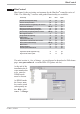
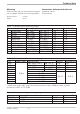
Technical data
KS 90-1 / KS 92-1 75
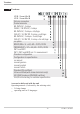
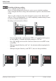
Process value input INP1
Mains supply Supplementary input INP2
Optional input INP3
Digital input di1, di2
Relay OUT1 RS422/485 interface
Relay OUT2 Digital inputs di2, 3
Relay OUT3 Universal output OUT3
Relay OUT4 Universal output OUT4
Transmitter supply U
T