
Manual

4.4 Switching behaviuor
With these controllers, configuration parameter CYCL (ConF/ Cntr/ CYCL)
can be used for matching the cycle time of 2-point and 3-point controllers. This
can be done using the following 4 methods.
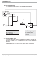
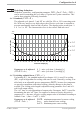
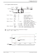
4.4.1 Standard ( CyCl= 0 )
The adjusted cycle times t1 and t2 are valid for 50% or -50% correcting varia
-
ble. With very small or very high values, the effective cycle time is extended to
prevent unreasonably short on and off pulses. The shortest pulses result from ¼
x t1 or¼x t2. The characteristic curve is also called “bath tub curve”
Parameters to be adjusted: t1 : min. cycle time 1 (heating) [s]
( PArA/ Cntr) t2 : min. cycle time 2 (cooling) [s]
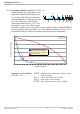
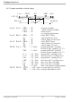
4.4.2 Switching attitude linear ( CyCl= 1 )
For heating (Y1), the standard method (see chapter 4.4.1) is used. For cooling
(Y2), a special algorithm for cooling with water is used. Generally, cooling is en
-
abled only at an adjustable process temperature (E.H2O), because low temperatu
-
res prevent evaporation with related cooling, whereby damage to the plant is
avoided. The cooling pulse length is adjustable using parameter t.on and is fi
-
xed for all output values.
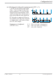
The “off” time is varied dependent of output value. Parameter t.off is used for
determining the min “off” time. For output of a shorter off pulse, this pulse is
suppressed, i.e. the max. effective cooling output value is calculated according to
formula t.on /(t.on + t.off) w 100%.
Parameters to be adjusted: E.H2O: minimum temperature for water cooling
( PArA / Cntr) t.on: pulse duration water cooling
t.off: minimum pause water cooling
Configuration level
KS 90-1 / KS 92-1 45 Switching behaviuor
0,0
1,0
2,0
3,0
4,0
5,0
6,0
5 101520253035404550556065707580859095
Controller output [%]
re
l
at
i
ve cycle duration
T/T
1
t1
2xt1
3xt1
4xt1