PMA Prozeß- und Maschinen-Automation GmbH Industrial and process controller KS 90-1and KS 92-1 KS90-1 KS92-1 KS90-1 KS92-1 Operating manual English advanced line 9499-040-62911 Valid from: 8499
û BlueControl More efficiency in engineering, more overview in operating: The projecting environment for the BluePort® controllers on ! s ON ate I pd de T N U e. E and nlin D T ATrsion ma-o A-C e .p PM V ni ww r on i M w o Description of symbols in the text: on the device: g General information a Follow the operating instructions a General warning l Attention: ESD-sensitive devices © PMA Prozeß- und Maschinen-Automation GmbH • Printed in Germany All rights reserved.
Contents 1 2 2.1 2.2 3 3.1 3.2 3.3 3.4 3.5 Mounting . . . . . . . . . . . . . . . . . . . . . . . . . . . . . . 5 Electrical connections . . . . . . . . . . . . . . . . . . . . . . . 6 Connecting diagram . . . . . . . . . . . . . . . . . . . . . . . 6 Terminal connection . . . . . . . . . . . . . . . . . . . . . . . . 7 Operation . . . . . . . . . . . . . . . . . . . . . . . . . . . . . 11 Front view . . . . . . . . . . . . . . . . . . . . . . . . . . . . 11 Behaviour after power-on . . . . . . . . . . .
.4.2 4.4.3 4.4.4 4.5 Configuration examples . . . . . . . . . . . . . . . . . . . . . . 48 4.5.1 4.5.2 4.5.3 4.5.4 4.5.5 4.5.6 4.5.7 4.5.8 5 5.1 5.2 5.3 . . . . . . . . . . . . . . . . . . . . . . . . . . . . . . . . . . . . . . . . . . . . . . . . . . . . . . . . . . . . . . . . . . . . . . . . . . . . . . . . . . . . . . . . . . . . 48 49 50 51 52 53 54 55 56 56 57 60 Input Inp.1 and InP.3 . . . . . . . . . . . 60 Input InP.2 . . . . . . . . . . . . . . . . . . . . . . . . . .
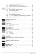
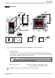
Mounting 1 Mounting °C °F para func Ada Err 4 921.2 F Loc locking switch F è C SP.E Ada Err (1.77" +0.02) SP.E SP.2 o para func SP.2 45 1200 +0,6 3 run 96 (3.78") 1199 2 920.1 44 SP.E 3 SP.2 run 2 1 96 1 +0,8 (4 18 (3.62" +0.03) 1 ") 5 .6 (0 1. .0 .1 4. 0 .0 .4 ") 10 ( 92 ") 4 0. 92 +0,8 92 +0,8 min.48 (1.89") 8 11 10 KS 92-1 advanced 96 KS 92-1 advanced KS 90-1 advanced 48 (1.89") max. 60°C min. 0°C max. 95% rel.
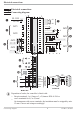
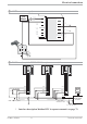
Electrical connections 2 Electrical connections 2.1 Connecting diagram 90...250V 24 V UC 1 2 3 4 5 6 OUT1 2 OUT3 3 10 11 12 V KS90-1.4 -... KS90-1.5 -... OUT4 13 14 15 V KS90-1.2 -... 5 d bc e a 7 di2 4 5 6 7 8 9 10 11 12 13 14 15 (16) 17 7 8 9 OUT2 di1 1 2 3 Option 1 g HC mA f mA 0% 100% INP2 5 INP3 6 KS90-1..-.1...
Electrical connections 2.2 Terminal connection Power supply connection 1 See chapter "Technical data" Connection of outputs OUT1/2 2 2 OUT1/2 heating/cooling Relay outputs (250V/2A), potential-free changeover contact 1 L Connection of outputs OUT3/4 3 a relay (250V/2A), potential-free changeover contact universal output b current (0/4...20mA) c voltage (0/2...10V) d transmitter supply e logic (0..20mA / 0..
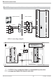
Electrical connections Connection of inputs di2/3 8 (option) Digital inputs (24VDC external), galvanically isolated, configurable as switch or push-button Connection of output UT 9 (option) Supply voltage connection for external energization Connection of outputs OUT5/6 0 (option) Digital outputs (opto-coupler), galvanic isolated, common positive control voltage, output rating: 18...
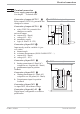
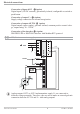
Electrical connections 3 OUT3 transmitter supply 13V 22mA - 10 + 11 11 12 12 13 14 15 13 + 14 15 - (16) 17 1 3 K 2 10 11 12 1 13 14 14 1 15 DATA A 11 12 13 14 1 15 15 (2) (2) 3 3 3 4 4 4 5 5 5 6 6 6 7 7 7 8 8 8 9 9 9 10 10 10 11 12 RGND 11 12 13 RGND 14 DATA B 15 (16) RT 10 (2) 14 DATA B 11 13 13 RT = 120...
Electrical connections 3 OUT3 as logic output with solid-state relay (series and parallel connection) Series connection Parallel connection SSR _ Imax=22mA 4V + SSR _ Imax=22mA SSR _ 10 11 12V + 4V 12V + 12 SSR _ Logic 10 11 12 SSR _ 4V + + KS9x-1 connecting example: L1 L2 Fuse Fuse KS90-1 3 4 5 6 7 8 9 10 11 Logik 12 13 14 15 4 5 6 7 8 9 10 11 12 13 14 Fuse 1 1 2 3 2 Contactor 3 4 TB 40-1 Temperaturelimiter 1 2 1 TB 40-1 Temperaturelimiter Standard-version (3 Relays): T
Operation 3 Operation 3.1 Front view 1199 °C °F p para f func A Ada Err 1200 §" SP.E 1 2 2 3 9 0 3 5 6 7 8 SP.2 ! $ F ( 1 $ % & / ( 2 3 4 920.1 o para func 4 Ada Err C 921.2 9 §"! 0 F % ( 1 3 5 7 9 ! § 1 SP.E 4 SP.2 / & 3 SP.E 4 5 6 7 8 2 SP.2 1 / & % $ Statuses of switching outputs OuT.1...
Operation 3.2 Behaviour after power-on After supply voltage switch-on, the unit starts with the operating level. The unit is in the condition which was active before power-off. If the controller was in manual mode at supply voltage switch-off, the controller will re-start with the last output value in manual mode at power-on. 3.3 Operating level The content of the extended operating level is determined by means of BlueControl (engineering tool).
Operation 3.4 Error list / Maintenance manager With one or several errors, the extended operating level always starts with the error list. Signalling an actual entry in the error list (alarm, error) is done by the Err LED in the display. To reach the error list press Ù twice. Err LED status blinks (status 2) lit (status 1) off (status 0) Signification Alarm due to existing error Error removed, alarm not acknowledged No error, all alarm entries deleted 1199 °C °F para func Ada Err 1200 SP.E SP.
Operation Description Cause Heating current - Current flow in heating short circuit circuit with controller off (SSR) - SSR defective LooP Control loop - Input signal defective or not alarm (LOOP) connected correctly Name SSr - Output not connected correctly AdA.H Self-tuning - See Self-tuning heating error status AdA.C - See Self-tuning cooling error status dAC LiM.1/ 2/3 Inf.1 Inf.2 E.5 dp.1 dp.2 dp.3 dp.
Operation Self-tuning heating ( ADA.H) and cooling ( ADA.C) error status: Error Description status 0 No error 3 Faulty control 4 5 6 7 8 action No response of process variable Low reversal point Danger of exceeded set-point (parameter determined) Output step change too small (dy > 5%) Set-point reserve too small Behaviour Re-configure controller (inverse i direct) The control loop is perhaps not closed: check sensor, connections and process Increase ( ADA.H) max. output limiting Y.Hi or decrease ( ADA.
Operation 3.5 Self-tuning For determination of optimum process parameters, self-tuning is possible. After starting by the operator, the controller makes an adaptation attempt, whereby the process characteristics are used to calculate the parameters for fast line-out to the set-point without overshoot. The following parameters are optimized when self-tuning: Parameter set 1: Pb1 - Proportional band 1 (heating) in engineering units [e.g.
Operation 3.5.2 Optimization after start-up or at the set-point The two methods are optimization after start-up and at the set-point. As control parameters are always optimal only for a limited process range, various methods can be selected dependent of requirements. If the process behaviour is very different after start-up and directly at the set-point, parameter sets 1 and 2 can be optimized using different methods. Switch-over between parameter sets dependent of process status is possible (see page ).
Operation 3.5.4 Step attempt after start-up Condition: - tunE = 0 and sufficient set-point reserve provided or - tunE = 2 The controller outputs 0% correcting variable or Y.Lo and waits, until the process is at rest (see start-conditions on page 8). Subsequently, a correcting variable step change to 100% is output. The controller attempts to calculate the optimum control parameters from the process response.
Operation Optimization-at-the-set-point procedure: The controller uses its instantaneous parameters for control to the set-point. In lined out condition, the controller makes a pulse attempt. This pulse reduces the correcting variable by max. 20% 1, to generate a slight process value undershoot. The changing process is analyzed and the parameters thus calculated are recorded in the controller. The optimized parameters are used for line-out to theset-point.
Operation 3.5.7 Optimization at the set-point for 3-point stepping controller With 3-point stepping controllers, the pulse attempt can be made with or without position feedback. Unless feedback is provided, the controller calculates the motor actuator position internally by varying an integrator with the adjusted actuator travel time. For this reason, precise entry of the actuator travel time (tt), as time between stops is highly important.
Operation 3.5.8 Self-tuning start Start condition: w For process evaluation, a stable condition is required. Therefore, the controller waits until the process has reached a stable condition after self-tuning start. The rest condition is considered being reached, when the process value oscillation is smaller than ± 0,5% of (rnG.H - rnG.L). w For self-tuning start after start-up, a 10% difference from (SP.LO ... SP.Hi) is required. g Self-tuning start can be blocked via BlueControl® (engineering tool) ( P.
Operation 3.5.10 Acknowledgement procedures in case of unsuccessful self-tuning 1. Press keys Ù and È simultaneously: The controller continues controlling using the old parameters in automatic mode. The Err LED continues blinking, until the self-tuning error was acknowledged in the error list. 2. Press key Ò (if configured): The controller goes to manual mode. The Err LED continues blinking, until the self-tuning error was acknowleged in the error list. 3.
Operation 3.5.11 Examples for self-tuning attempts (controller inverse, heating or heating/cooling) Start: heating power switched on Heating power Y is switched off (1). When the change of process value X was constant during one minute (2), the power is switched on (3). At the reversal point, the self-tuning attempt is finished and the new parameter are used for controlling to set-point W. Start: heating power switched off The controller waits 1,5 minutes (1). Heating power Y is switched on (2).
Operation 3.6 Manual self-tuning The optimization aid can be used with units on which the control parameters shall be set without self-tuning. For this, the response of process variable x after a step change of correcting variable y can be used. Frequently, plotting the complete response curve (0 to 100%) is not possible, because the process must be kept within defined limits.
Operation Parameter adjustment effects Parameter Control Pb1 higher increased damping lower reduced damping td1 higher reduced damping lower increased damping ti1 higher increased damping lower reduced damping Line-out of disturbances slower line-out faster line-out faster response to disturbances slower response to disturbances slower line-out faster line-out Formulas Start-up behaviour slower reduction of duty cycle faster reduction of duty cycle faster reduction of duty cycle slower reduction of
Operation 3.8 Alarm handling Max. three alarms can be configured and assigned to the individual outputs. Generally, outputs OuT.1... OuT.6 can be used each for alarm signalling. If more than one signal is linked to one output the signals are OR linked. Each of the 3 limit values Lim.1 … Lim.3 has 2 trigger points H.x (Max) and L.x (Min), which can be switched off individually (parameter = “OFF”). Switching difference HYS.x and delay dEl.x of each limit value is adjustable.
Operation g g The variable to be monitored can be selected seperately for each alarm via configuration The following variables can be monitored: w process value w control deviation xw (process value - set-point) w control deviation xw + suppression after start-up or set-point change After switching on or set-point changing, the alarm output is suppressed, until the process value is within the limits for the first time. At the latest after expiration of time 10 ti1, the alarm is activated.
Operation 3.9 Operating structure After supply voltage switch-on, the controller starts with the operating levels. The controller status is as before power off. 1199 Ù 1200 1199 para PArA 3 sec. Ì Ù PASS 1199 para Ù ConF Ì 1199 CAL Ì PASS Ù PASS 1199 Ù End g PArA - level: At PArA - level, the right decimal point of the bottom display line is lit continuously. g ConF - level: At ConF - level, the right decimal point of bottom display line blinks.
Configuration level 4 Configuration level 4.1 Configuration survey Y.2 OuT.0 Y.1 Lim.1 Out.1 Y.2 Lim.2 Lim.3 dAc.A O.Src Lim.1 O.FAI Lim.2 Y.1 Lim.3 LP.AL Y.2 dAc.A HC.AL Lim.1 LP.AL HC.SC Lim.2 HC.AL P.End Lim.3 HC.SC FAi.1 dAc.A P.End FAi.2 LP.AL FAi.1 FAi.3 HC.AL FAi.2 dP.Er HC.SC FAi.3 Othr Display, operation, interface O.Act O.Act LOGI Digital inpu ts O.tYP O.tYP Y.1 Out.5/6 Output 5/6 OUt.4 Output 4 OUt.3 Output 3 OUt.2 Output 2 O.Act See output 1 Fnc.1 Src.1 Fnc.
Configuration level 4.2 Configuration parameters Cntr Name SP.Fn Value range Description 0 8 C.tYP 0 1 2 3 4 5 6 7 8 C.Fnc 0 1 2 3 4 5 6 C.dif 0 1 mAn 0 1 C.Act 0 1 Configuration parameters Basic configuration of setpoint processing set-point controller can be switched over to external set-point (-> LOGI/ SP.E) standard controller with external offset (SP.
Configuration level Name FAIL Value range Description Default 1 Behaviour at sensor break 0 controller outputs switched off 1 y = Y2 2 y = mean output. The maximum permissible output can be adjusted with parameter Ym.H. To prevent determination of inadmissible values, mean value formation is only if the control deviation is lower than parameter L.Ym. rnG.L -1999...9999 X0 (start of control range) 1 -100 rnG.H -1999...
Configuration level Name Value range 4 5 6 7 8 9 10 18 20 Description Default thermocouple type S (0...1760°C), PtRh-Pt10% thermocouple type R (0...1760°C), PtRh-Pt13% thermocouple type T (-200...400°C), Cu-CuNi thermocouple type C (0...2315°C), W5%Re-W26%Re thermocouple type D (0...2315°C), W3%Re-W25%Re thermocouple type E (-100...1000°C), NiCr-CuNi thermocouple type B (0/100...1820°C), PtRh-Pt6% special thermocouple Pt100 (-200.0 ... 100,0 °C) ( -200,0 ...
Configuration level InP.2 Name I.Fnc Value range Description Default 1 Function selection of INP2 0 no function (subsequent input data are skipped) 1 heating current input 2 external set-point (SP.E) 3 Yp input 4 Second process value X2 5 External positioning value Y.E (switch-over r LOGI / Y.E) 6 no controller input (e.g. transmitter input instead) 7 Process value x1 S.tYP 30 Sensor type selection 30 0...20mA / 4...20mA 1 31 0...50mA AC 1 50 Potentiometer ( 0...160 Ohm) 1 51 Potentiometer ( 0...
Configuration level Name S.Lin Value range Description 0 1 S.tYP Corr In.F fAI3 1 Default 0 Linearization (onlyatS.tYP=30(0..20mA)and40(0..10V)adjustable) none Linearization to specification. Creation of linearization table with BlueControl (engineering tool) possible. The characteristic for KTY 11-6 temperature sensors is preset. 30 Sensor type selection 0 thermocouple type L (-100...900°C) , Fe-CuNi DIN 1 thermocouple type J (-100...1200°C) , Fe-CuNi 2 thermocouple type K (-100...
Configuration level Lim Name Fnc.1 Fnc.2 Fnc.3 Value range Description 0 1 2 3 4 Src.1 Src.2 Src.3 0 1 2 3 4 5 6 7 8 9 11 HC.AL 0 1 2 LP.AL 0 1 dAc.A 0 1 KS 90-1 / KS 92-1 Function of limit 1/2/3 switched off measured value monitoring Measured value monitoring + alarm latch. A latched limit value can be reset via error list or via a digital input, or by pressing key Ò or è (-> LOGI/ Err.
Configuration level Name Value range Description â Hour OFF...9999 Operating hours (only visible with BlueControl !) 99 Swit OFF...9999 Output switching cycles (only visible with BlueControl !) 99 â Default OFF OFF Out.1 and Out.2 Name O.Act Value range Description 0 1 Y.1 Y.2 Lim.1 Lim.2 Lim.3 dAc.A 0 1 0 1 0 1 LP.AL 0 1 HC.AL 0 1 HC.SC 0 1 FAi.1 FAi.2 FAi.3 dP.
Configuration level Out.3 Name O.tYP and Value range Out4 Description Signal type selection OUT3 relay / logic (only visible with current/logic voltage) 0 ... 20 mA continuous (only visible with current/logic/voltage) 4 ... 20 mA continuous (only visible with current/logic/voltage) 0...10 V continuous (only visible with current/logic/voltage) 2...10 V continuous (only visible with current/logic/voltage) transmitter supply (only visible without OPTION) O.
Configuration level Name HC.AL Value range 0 1 HC.SC 0 1 FAi.1 FAi.2 FAi.3 dP.Er 0 1 0 1 fOut 0 1 Description Default Heating current alarm signal (only visible when O.TYP=0) 0 not active active Solid state relay (SSR) short circuit signal (only visible when O.TYP=0) not active active INP1/ INP2 / INP3 error (only visible when O.TYP=0) not active active PROFIBUS error not active active: Profibus trouble, no communication with this instrument.
Configuration level Name SP.E Value range Description 0 1 2 3 4 5 Y2 0 2 3 4 5 6 Y.E 0 1 2 3 4 5 6 mAn 0 1 2 3 4 5 6 C.oFF 0 2 3 4 5 6 m.Loc 0 2 3 4 5 KS 90-1 / KS 92-1 Switching to external setpoint SP.
Configuration level Name Err.r Value range Description 0 2 3 4 5 6 Pid.2 0 2 3 4 5 I.Chg 0 2 3 4 5 di.
Configuration level Name Value range dP.AD 0...126 Description Profibus address bc.up Behaviour as backup controller (see page ) 0 No backup functionality 1 With backup functionality O2 Entering parameter for O in ppm or % 0 Parameter for O -function in ppm 1 Parameter for O -function in % Unit Unit 0 without unit 1 °C 2 °F dP Decimal point (max.
Configuration level Name Value range IExo Description Default 0 Block extended operating level (only visible with BlueControl!) 0 1 ILat Pass IPar ICnf ICal CDis3 TDis3 T.dis3 T.InF1 T.InF2 Released Blocked Suppression error storage (visible only with BlueControl !) 0 0 No: error message remain in the error list until acknowledgement. 1 Yes alarms are deleted from the error list as soon as corrected OFF...
Configuration level Name In.2 Ou.2 : : Value range Description -999.0..99999 Input value 2 The signal is in [µV] or in [[] dependent of input type 0,001...9999 Output value 2 Signal assigned to In.2 : : : : In.16 -999.0..99999 Input value 16 The signal is in [µV] or in [[] dependent of input type Ou.16 0,001...9999 Output value 1 6 Signal assigned to In.
Configuration level 4.3 Set-point processing The set-point processing structure is shown in the following picture: 1199 °C °F para func Ada Err 1200 Xeff Internal set-point SP.E SP.2 Ü SP.Hi 0 + 8 * SP.Lo External set-point SP.E INP2 Ü Limitation Ö 0/4...20 mA Effektive r.SP set-point 2. set-point SP.2 - LED Ramp The ramp starts at process value with the following switchings: Index: Ü : int/ext-setpoint switching * : configuration SP.Fn Ö : SP / SP.
Configuration level 4.4 Switching behaviuor With these controllers, configuration parameter CYCL (ConF/ Cntr/ CYCL) can be used for matching the cycle time of 2-point and 3-point controllers. This can be done using the following 4 methods. 4.4.1 Standard ( CyCl= 0 ) The adjusted cycle times t1 and t2 are valid for 50% or -50% correcting variable. With very small or very high values, the effective cycle time is extended to prevent unreasonably short on and off pulses.
Configuration level 70 -95% -67% -80% -100% -92% Parameter: t.on = 0.4 sec t.off = 0.2 sec 60 Effective controller output -90% -87% -82% 4.4.3 Switching attitude non-linear ( CyCl= 2 ) With this method, the cooling power is nort.on t.off mally much higher than the heating power, i.e. the effect on the behaviour during transition from heating to cooling may be negative. The cooling curve ensures that the control intervention with 0 to -70% correcting variable is very weak.
Configuration level 4.4.4 Heating and cooling with constant period ( CyCl= 3 ) 1 and t2 are met in the overall output tp range . To prevent unreasonably short t1/ t2 pulses, parameter tp is used for adjusting the shortest pulse duration. With 50% 30% small correcting values which require a pulse shorter than the value adjusted in tp tp, this pulse is suppressed. However, t1/ t2 the controller stores the pulse and totalizes further pulses, until a pulse of duration tp can be output.
Configuration level 4.5 Configuration examples 4.5.1 On-Off controller / Signaller (inverse) InL.1 SP.LO SP SP.Hi InH.1 InP.1Ê 100% SH Out.1Â 0% ConF / Cntr: SP.Fn C.Fnc C.Act =0 =0 =0 ConF / Out.1: O.Act Y.1 Hys.l Hys.H SP.LO SP.Hi =0 =1 = 0...9999 = 0...9999 = -1999...9999 = -1999...9999 PArA / Cntr: PArA / Cntr: PArA / SEtP: g set-point controller signaller with one output inverse action (e.g. heating applications) action Out.
Configuration level 4.5.2 2-point controller (inverse) SP.LO InL.1 InP.1Ê SP SP.Hi InH.1 PB1 100% Out.1Â 0% ConF / Cntr: SP.Fn C.Fnc C.Act ConF / Out.1: O.Act Y.1 Pb1 PArA / Cntr: PArA / SEtP: g ti1 td1 t1 SP.LO SP.Hi = 0 = 1 = 0 set-point controller 2-point controller (PID) inverse action (e.g. heating applications) = 0 action Out.1 direct = 1 control output Y1 active = 1...9999 proportional band 1 (heating) in units of phys. quantity (e.g. °C) = 0,1...
Configuration level 4.5.3 3-point controller (relay & relay) InL.1 SP.LO InP.1Ê SP PB1 100% SP.Hi InH.1 PB2 100% Out.1Â Out.2Â 0% 0% ConF / Cntr: SP.Fn C.Fnc C.Act ConF / Out.1: O.Act Y.1 Y.2 O.Act Y.1 Y.2 Pb1 ConF / Out.2: PArA / Cntr: Pb2 PArA / SEtP: Configuration examples ti1 ti2 td1 td2 t1 t2 SH SP.LO SP.Hi = 0 = 3 = 0 set-point controller 3-point controller (2xPID) action inverse (e.g. heating applications) = 0 action Out.
Configuration level 4.5.4 3-point stepping controller (relay & relay) SP.LO InL.1 InP.1Ê SP SP.Hi InH.1 PB1 100% 100% SH Out.1Â 0% SP.Fn C.Fnc C.Act = 0 = 4 = 0 ConF / Out.1: O.Act Y.1 Y.2 O.Act Y.1 Y.2 Pb1 = = = = = = = ti1 td1 t1 SH tP tt SP.LO SP.Hi = = = = = = = = PArA / Cntr: PArA / SEtP: g 0% ConF / Cntr: ConF / Out.2: Out.2Â set-point controller 3-point stepping controller inverse action (e.g. heating applications) 0 action Out.
Configuration level 4.5.5 Continuous controller (inverse) SP.LO InL.1 InP.1Ê SP SP.Hi InH.1 PB1 20 mA Out.3Â 0/4 mA ConF / Cntr: SP.Fn C.Fnc C.Act = 0 = 1 = 0 ConF / Out.3: O.tYP Out.0 Out.1 Pb1 = = = = 1/2 -1999...9999 -1999...9999 1...9999 ti1 td1 t1 SP.LO SP.Hi = = = = = 0,1...9999 0,1...9999 0,4...9999 -1999...9999 -1999...9999 PArA / Cntr: PArA / SEtP: g g set-point controller continuous controller (PID) inverse action (e.g. heating applications) Out.
Configuration level 4.5.6 D - Y - Off controller / 2-point controller with pre-contact SP.LO InL.1 SP InP.1Ê SP.Hi InH.1 PB1 100% Out.1Â 0% Out.2Â SH ConF / Cntr: SP.Fn C.Fnc C.Act d.SP = 0 = 2 = 0 set-point controller D -Y-Off controller inverse action (e.g. heating applications) ConF / Out.1: O.Act = 0 action Out.1 direct Y.1 = 1 control output Y1 active Y.2 = 0 control output Y2 not active ConF / Out.2: O.Act = 0 action Out.2 direct Y.1 = 0 control output Y1 not active Y.
Configuration level 4.5.7 Continuous controller with position controller ( Cntr/ C.Fnc = 6 ) SP W INP.1 X OUT.4 Ycontinuous Ypid Master controller W OUT.1 Y.1 INP.2 X M Y.2 OUT.2 Position controller Basically, this controller function is a cascade. A slave controller with three-point stepping behaviour working with position feedback Yp as process value (INP2 or INP3) is added to a continuous controller. ConF / Cntr SP.Fn = 0 setpoint controller C.
Configuration level 4.5.8 Measured value output phys. quantity Out.1 mA / V phys. quantity Out.0 20mA 10V 0/4mA 0/2V 90...250VAC 24VUC } NL 1 2 1 2 3 3 4 5 6 7 8 9 OUT3 OUT4 10 11 12 U 13 14 15 4 5 6 7 8 9 10 11 12 13 14 U 15 (16) INP1 17 + ConF / Out.3 / 4: O.tYP = = = = Out.0 = 1 2 3 4 -1999...9999 Out.1 = -1999...9999 O.Src = 3 KS 90-1 / KS 92-1 55 Out.3/ 4 0...20mA continuous Out.3/ 4 4...20mA continuous Out.3/ 4 0...10V continuous Out.3/ 4 2...10V continuous scaling Out.
Parameter setting level 5 Parameter setting level 5.1 Parameter survey Ì Pb1 Pb12 SP.Lo InL.1 Inl.2 InL.3 L.1 Pb2 Pb22 SP.Hi OuL.1 OuL.2 OuL.3 H.1 ti1 ti12 SP.2 InH.1 InH.2 InH.3 HYS.1 ti2 ti22 r.SP OuH.1 OuH.2 OuH.3 dEl.1 td1 td12 tF.1 td2 td22 E.tc tF.2 tF.3 End Lim Limit value functions Input 3 InP.3 Input 2 InP.2 Input 1 InP.1 PAr.2 SEtP Set-point and process value Parameter setting level 2. set of parameters È Cntr Control and self-tuning PArA L.2 E.tc H.2 t1 HYS.
Parameter setting level g Return to the beginning of a group is by pressing the Ù key for 3 sec. If for 30 sec. no keypress is excecuted the controler returns to the process value and setpoint display ( Time Out = 30 sec. ) 5.2 Parameters Cntr Name Pb1 Pb2 ti1 ti2 td1 td2 t1 Value range 1...9999 1 1...9999 1 0,1...9999 0,1...9999 0,1...9999 0,1...9999 0,4...9999 t2 0,4...9999 SH 0...9999 Hys.l Hys.H d.SP 0...9999 0...9999 -1999...9999 tP tt Y.Lo Y.Hi Y2 Y.0 Ym.H L.Ym 0,1...9999 3...9999 -120..
Parameter setting level PAr.2 Name Pb12 Value range Description Default 1...9999 1 Proportional band 1 (heating) in phys. dimensions (e.g. 100 Pb22 1...9999 1 Ti22 Ti12 Td12 Td22 0,1...9999 0,1...9999 0,1...9999 0,1...9999 °C), 2. parameter set Proportional band 2 (cooling) in phys. dimensions (e.g. °C), 2. parameter set Integral action time 2 (cooling) [s], 2. parameter set Integral action time 1 (heating) [s], 2. parameter set Derivative action time 1 (heating) [s], 2.
Parameter setting level Name InL.3 OuL.3 InH.3 OuH.3 t.F3 Etc.3 Value range -1999...9999 -1999...9999 -1999...9999 -1999...9999 -1999...9999 0...100 (°C) 32...212 (°F Description Input value for the lower scaling point Displayed value for the lower scaling point Input value for the upper scaling point Displayed value for the upper scaling point Filter time constant [s] External cold-junction reference temperature (external TC) Default 0 0 20 20 0 OFF Lim Name Value range L.1 -1999...9999 H.1 -1999..
Parameter setting level 5.3 Input scaling When using current, voltage or resistance signals as input variables for InP.1, InP.2 or/and InP.3 scaling of input and display values at parameter setting level is required. Specification of the input value for lower and higher scaling point is in the relevant electrical unit (mA / V / W). phys. quantity OuH.x phys. quantity mA / V OuL.x InH.x mA/V InL.x S.tYP 30 (0...20mA) 40 (0...10V) Input signal 0 … 20 mA 4 … 20 mA 0 … 10 V 2 … 10 V InL.x 0 4 0 2 OuL.
Calibration level 6 Calibration level Measured value correction ( CAL) is only visible if ConF / InP.1 / Corr = 1 or 2 is chosen. The measured value can be matched in the calibration menu ( CAL). Two methods are available: Offset correction ( ConF/ InP.1 / Corr =1 ): display standard setting offset correction w possible on-line at the process OuL.1new OuL.1old InL.1 X 2-point correction ( ConF/ InP.
Calibration level Offset correction ( ConF/ InP.1 / Corr =1 ): r 1199 °C °F para func Ada Err 1200 SP.E SP.2 r Ù r PArA 3 sec. Ì : CAL r Ù r InP.1 r Ù r InL.1 r Ù r OuL.1 È r Ù Ì r End r Ù InL.1: The input value of the scaling point is displayed. The operator must wait, until the process is at rest. Subsequently, the operator acknowledges the input value by pressing key Ù. OuL.1: The display value of the scaling point is displayed. Before calibration, OuL.1 is equal to InL.1.
Calibration level 2-point correction ( ConF/ InP.1 / Corr = 2): 1199 °C °F 1200 r Ù r 3 sec. PArA Ì SP.E SP.2 r para func Ada Err ConF r Ì CAL r Ùr InP.1 r Ù r InL.1 r Ù È È Ì InL1 InP.2 OuL.1 È Ì InP.3 È Ì Ù End Ù È rÙ Ì InH.1 r Ù È InH.1 Ù OuH.1 È rÙ Ì InL.1: The input value of the lower scaling point is displayed. The operator must adjust the lower input value by means of a process value simulator and confirm the input value by pressing key Ù. OuL.
Special functions 7 Special functions 7.1 DAC®– motor actuator monitoring (Digital Actor Control DAC®) With all controllers with position feedback Yp, the motor actuator can be monitored for functional troubles. The DAC® function can be started by chosing the parameter C.Fnc = 5 or 6 at the configuration level ( ConF): w ConF / Cntr / C.Fnc = 5 3-point-stepping controller with position feedback Yp as potentiometer w ConF / Cntr / C.
Special functions Functioning of the DAC function No input filter should be defined for the Yp input ( PArA / InP.x / t.Fx = 0 ). Therewith no wrong detection of blocking or wrong method of operation can be recognized. The automatic calibration can be used with drives outfitted with spring assembly. Execution of the calibration: It is controlled if the mean alteration between two messurements is enough for the DAC monitoring.
Special functions 7.2 O2 measurement This function is available only on the instrument version with INP3. As the O2-measurement result range can extend over many decades, automatic display switch-over between “ % ” and “ppm“ was realized. The instantaneous unit is displayed in the lower line. With set-point changing via keys I or D, the unit of the set-point and of the other parameters is displayed. Lambda probes (l probes) are used as sensors.
Special functions 7.2.2 Configuration: Oxygen measurement Oxygen measurement with heated lambda probe Controller r Process value processing r 7: O2 functions with constant probe temperature Cntr r C.tYP 7 O2-const Oxygen measurement with non-heated lambda probe Controller r Process value processing r O2 functions with measured probe temperature Cntr r C.tYP 8 O2+temp Input 1 r Function INP1 r 7: process value X1 InP.1 r 1.
Special functions 7.3 Linearization Linearization for inputs INP1 or INP3 Access to table “ Lin” is always with selection of sensor type S.TYP = 18: special thermocouple in INP1 or INP3, or with selection of linearization S.Lin 1: special linearization. Dependent of input type, the input signals are specified in µV or in Ohm dependent of input type. With up to 16 segment points, non-linear signals can be simulated or linearized. Every segment point comprises an input (In.1 … In.16) and an output (Ou.
Special functions 7.4 Loop alarm The loop alarm monitors the control loop for interruption (not with three-point stepping controller and not with signallers.) With parameter LP.AL switched to 1(= loop alarm active), an interruption of the control loop is detected, unless the process value reacts accordingly with Y=100% after elapse of 2xTi. The loop alarm shows that the control loop is interrupted. You should check heating or cooling circuit, sensor, controller and motor actuator.
Special functions 7.6 KS9x-1 as Modbus master a This function is only selectable with BlueControl (engineering tool)! Additions othr Name MASt Cycl AdrO AdrU (only visible with BlueControl!) Value range Description Controller is used as Modbus master 0 Slave 1 Master 0...200 Cycle time [ms] for the Modbus master to transmit its data to the bus. 1...65535 Target address to which the with AdrU specified data is given out on the bus. 1...
BlueControl 8 BlueControl BlueControl is the projecting environment for the BluePort â controller series of PMA.
Versions 9 Versions KS 90-1 Format 48 x 96 KS 92-1 Format 96 x 96 0 2 Flat-pin connectors Screw terminals 90..250V AC, 4 relays 24VAC / 18..30V DC, 4 relays 90..250V AC, 3 relays + mA/logic 24V AC / 18..30V DC, 3 relays + mA/logic 90..250V AC, 2 relays + 2x mA/logic 24V AC / 18..30V DC, 2 relays + 2x mA/logic no option RS422/485 + UT + di2, di3 + OUT5, OUT6 PROFIBUS-DP + UT + di2,di3 + OUT5, OUT6 INP1 and INP2 INP1, INP2 and INP3 incl.
Versions Accessory equipment with ordering information Description Heating current transformer 50A AC PC-adaptor for the front-panel interface Standard rail adaptor Operating manual Operating manual Operating manual Operating manual Interface description Modbus RTU Interface description Modbus RTU BlueControl (engineering tool) BlueControl (engineering tool) BlueControl (engineering tool) KS 90-1 / KS 92-1 73 German English French Russian German English Mini Basic Expert Order no.
Technical data 10 Technical data INPUTS PROCESS VALUE INPUT INP1 Resolution: Decimal point: Dig. input filter: Scanning cycle: Measured value correction: > 14 bits 0 to 3 digits behind the decimal point adjustable 0,000...9999 s 100 ms 2-point or offset correction Span start, end of span: anywhere within measuring range Scaling: selectable -1999...9999 Linearization: 16 segments, adaptable with BlueControl Decimal point: adjustable Input circuit monitor: 12.
Technical data Nominal voltage Current sink (IEC 1131 type 1) Logic “0” Logic “1” Current requirement 24 V DC external -3...5 V 15...30 V approx.. 5 mA TRANSMITTER SUPPLY UT (OPTION) 22 mA / ³ 18 V Power: As analog outputs OUT3 or OUT4 and transmitter supply UT are connected to different voltage potentials, an external galvanic connection between OUT3/4 and UT is not permissible with analog outputs.
Technical data BEHAVIOUR WITH POWER FAILURE Shock test Ea (DIN IEC 68-2-27) Configuration, parameters and adjusted set-points, control mode: Non-volatile storage in EEPROM Shock: Duration: 15g 11ms Electromagnetic compatibility BLUEPORT FRONT INTERFACE Complies with EN 61 326-1 (for continuous, non-attended operation) Connection of PC via PC adapter (see "Accessory equipment"). The BlueControl software is used to configure, set parameters and operate the device.
Technical data Mounting Accessories delivered with the unit Panel mounting with two fixing clamps at top/ bot- Operating manual tom or right/left, high-density mounting possible Fixing clamps Mounting position: Weight: uncritical 0.27kg Table 1 Thermocouples measuring ranges Thermoelementtype L Fe-CuNi (DIN) J Fe-CuNi K NiCr-Ni N Nicrosil/Nisil S PtRh-Pt 10% R PtRh-Pt 13% T Cu-CuNi C W5%Re-W26%Re D W3%Re-W25%Re E NiCr-CuNi B * PtRh-Pt6% Measuring range -100...900°C -100...1200°C -100...1350°C -100...
Safety hints 11 Safety hints This unit was – built and tested in compliance with VDE 0411-1 / EN 61010-1 and – delivered in safe condition. – complies European guideline 89/336/EWG (EMC) and is provided with CE marking. – tested before delivery and passed the tests required by test schedule. – To maintain this condition and to ensure safe operation, the user must follow the hints and warnings given in this operating manual.
Safety hints SHUT-DOWN For taking the unit out of operation, disconnect it from all voltage sources and protect it against accidental operation. If the controller is connected with other equipment in the same signal loop, check that other equipment in the output circuit is not affected before switch-off. If necessary, suitable protective measures must be taken. MAINTENANCE, REPAIR AND MODIFICATION The units do not need particular maintenance.
Safety hints 11.1 Resetting to factory setting, or to a customer-specific data set In case of faultyconfiguration, the device can be reset to a default condition. Unless changed, this basic setting is the manufacturer-specific controller default setting. However, this setting may have been changed by means of the BlueControl® software. This is recommendable e.g. when completing commissioning in order to cancel accidental alteration easily.
Safety hints Safety switches 1 closed 2 open 3 open 4 open g g Levels Password any free free any none defined min. 1 disabled any Instrument reaction after confirming ”YES” by pressing Ù always factory reset Factory reset without prompt for the password Factory reset after entry of the correct pass number Factory reset is omitted Timeout Unless a key is pressed during 10 seconds, a timeout occurs and the instruments starts without copying the default data.
Index 0-9 2-point correction. . . . . . . . . . . . 61 A Alarm handling . . . . . . . . . . 26 - 27 B Bargraph . . . . . . . . . . . . . . . . 11 BlueControl. . . . . . . . . . . . . . . 71 Bus interface - Technical Data . . . . . . . . . . 76 C Calibration level (CAL) . . . . . . 61 - 63 Certifications . . . . . . . . . . . . . . 76 Configuration examples - 2-point controller . . . . . . . . . 49 - 3-point controller . . . . . . . . . 50 - 3-point stepping controller . . . . 51 - Continuous controller . .
Linearization . . . . . . . . . . . . . . 68 M Mainenance manager . . . . . . . 13 - 15 Manual tuning . . . . . . . . . . . . . 24 Modbus master . . . . . . . . . . . . . 70 Mounting. . . . . . . . . . . . . . . . . 5 O O2-measurement . . . . . . Offset correction . . . . . . Optimization at the setpoint Output OUT1 - Configuration . . . . . - Technical data . . . . . Output OUT2 - Technical data . . . . . Output OUT3 - Configuration . . . . . - Technical data . . . . . Output OUT4 - Technical data . . . .
2 Subject to alterations without notice Änderungen vorbehalten Sous réserve de toutes modifications © PMA Prozeß- und Maschinen-Automation GmbH P.O.B.