
Manual


9499 040 55811
Multiple transmitter and temperature controller KS 816
19
Termination resistors
All KS 816 versions are delivered without termination resistors at the bus connecti-
ons.
The resistors required for each bus must be added externally at the last unit on
both ends of the bus cable: either in the last connector (socket) or in a separate
termination connector (socket), which plugs into the free bus connection of the last
unit.
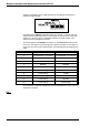
CAN-BUS: 9-pole sub-D socket with termination resistor. Only termination resistor,
not suitable for connecting a cable. PMA order no. 9407 800 90021
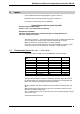
PROFIBUS: e.g. Siemens, bus connector,
types: 6ES7972-OBB10-OXAO or 6ES7972-OBB20-OXAO, or
6GK1 500-OEAOO. This connector is not available from PMA.
The standards or standard drafts valid for the relevant bus system are applicable.
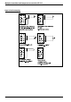
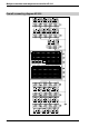
9 Indicator LEDs
There are 5 LEDs with the following signification above the lower input terminals:
PWR
This LED is on with the supply voltage applied.
COM
With CAN_BUS and RS422/485, this LED indicates data transmission between KS
816 and control system (PC or visualization) by flashing.
With PROFIBUS, the 4 different statuses are:
LED off: error signalling for "no bus access" (not addressed by the master)
LED on: OK cyclic data transmission running.
LED blinks: (2Hz) data transmission interrupted.
LED blinks: (4Hz) PROFIBUS parameters or configuration error.
AL1...AL3
With KS 816 configured so that it provides alarm functions, these LEDs are lit, when
the relevant alarm is pending.