8391
©PMA Prozeß- und Maschinen-Automation GmbH 1997. Printed in Germany All rights reserved. No part of this document may be reproduced or published in any form or by any means without prior written permission by the copyright owner. A publication of PMA Prozeß- und Maschinen- Automation GmbH Subject to change without notice. PMA Prozeß- und Maschinen-Automation GmbH P.O.
Multiple transmitter and temperature controller KS 816 Contents 1 Safety hints.................................................................................................................................5 1.1 Electromagnetic compatibility ....................................................................................................5 2 General........................................................................................................................................6 2.1 Versions .....
Multiple transmitter and temperature controller KS 816 4 9499 040 55811
Multiple transmitter and temperature controller KS 816 1 Safety hints Following the enclosed safety hints 9499 047 07101 is indispensable! For hints on the mains unit to be used, see section 4.3 Power supply. 1.1 Electromagnetic compatibility The unit conforms to European guideline 89/336/EEC and is provided with CE marking.
Multiple transmitter and temperature controller KS 816 2 General KS 816 is a microcomputer-based multi-loop temperature controller. Functions "setpoint reduction" and "heating/cooling with four alarms" make it particularly suitable for temperature control on plastics processing machinery, heated moulds, packaging machines, tempering units and similar thermal processes. With high-power heating elements (e.g.
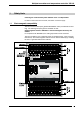
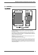
Multiple transmitter and temperature controller KS 816 3 Installation 3.1 Mounting KS 816 is provided for mounting on rails 35 x 7,5 (top-hat rail) to EN 50 022, EN 50 035, EN 50 045. Grounding is via a spring on the top-hat rail. Therefore, note that there must be a good conducting connection with the grounded mounting wall (layer of lacquer instead of conducting mounting wall, Eloxal, ...). If necessary, the clip-on rail must be grounded with a separate connection.
Multiple transmitter and temperature controller KS 816 3.2 Dismounting For dismounting, the leads need not be disconnected. Before removing the upper parts of the connectors, the upper parts and the corresponding lower parts must be marked, because these terminals are distortion-proof but not confusion-proof. For releasing the upper part of a terminal, the two red ejectors of a terminal row must be pressed towards the p.c.b. using a screwdriver, if necessary.
Multiple transmitter and temperature controller KS 816 4 Electrical connection • The max. permissible voltage against ground of the input and signal leads is 50 Veff. • Power supply leads must be kept separate from signal and input leads. • For output protection and interference suppression, connected contactors must be provided with protective circuitry to manufacturer specifications. 4.
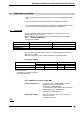
Multiple transmitter and temperature controller KS 816 Galvanic isolations The KS 816 galvanic isolations are shown below: Identical block shading means that the blocks are galvanically connected. (All inputs are galvanically connected.) 4.3 Power supply KS 816 is designed for 24V DC nominal supply voltage, range 18V to 30V, 5% ripple. The supply voltage must meet the conditions for protective low voltage (SELV) to CEI 364-4-41 [VDE 0100-410]. Power supply load by one KS 816: approx.
Multiple transmitter and temperature controller KS 816 5 Inputs (The complete KS 816 connecting diagram is given in section 7.). Illustrations with connecting examples are given in section 5.6. For all inputs, the following rules are applicable: Unused inputs must be short-circuited! Thermocouples and DC voltage: Terminal + and - of an input must be connected. Resistance thermometer: Configure unused controllers as for thermocouples or voltage. Shortcircuit the + and - terminal of an input.
Multiple transmitter and temperature controller KS 816 The controller inputs are not galvanically isolated. Therefore, thermocouple measurements above approx. 700°C and unsuitable thermocouples imply a risk of measurement errors. This effect is due to the fact that the isolation value between protective tube and thermocouple, dependent of construction type and insulation material, decreases to values of some kOhm from these values.
Multiple transmitter and temperature controller KS 816 5.2 Direct voltage 5.2.1 Range :-100mV...+100mV IN1T+...IN16T+ Direct voltages up to 100 mV can be connected instead of the thermocouples. These values can be scaled via corresponding software settings. The input resistance is approx. 100 kOhm. 5.2.2 Range : -10V...+10V IN1U+...IN16U+ Inputs INxU+ are provided for direct voltages within -10V and +10V. These values can be scaled via corresponding software settings. The input resistance is approx.
Multiple transmitter and temperature controller KS 816 Input circuit examples 14 9499 040 55811
Multiple transmitter and temperature controller KS 816 6 Outputs KS 816 has no outputs in the conventional sense. These are output via the (field) bus as • correcting variable in %, for continuous controllers and • digital information (on/off) for switching controllers Control of the final elements (relays,contactors, solid-state relays, magnetic valves) must be provided by a suitable output card of the control system. 6.
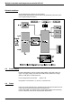
Multiple transmitter and temperature controller KS 816 Overall connecting diagram KS 816 16 9499 040 55811
Multiple transmitter and temperature controller KS 816 8 Digital interfaces The only possibility to communicate with controller KS 816 is via the digital interfaces. Process value read out as well as set-point or control parameter changing are via these interfaces. The two interface types are: 8.1 Engineering tool interface The PC interface is provided on all instrument versions. It is a special interface according to the ISO 1745 protocol. The relevant software, i.e.
Multiple transmitter and temperature controller KS 816 Address and Baudrate for the COM2 interface can be adjusted via hardware or software for each KS 800. Via hardware, the address is adjustable within ”01” and ”99”. In position ”00”, the address stored in EEPROM which can be changed via software will be used when switching on. Priority is given to the address adjusted via switch position. This address cannot be changed via software.
Multiple transmitter and temperature controller KS 816 Termination resistors All KS 816 versions are delivered without termination resistors at the bus connections. The resistors required for each bus must be added externally at the last unit on both ends of the bus cable: either in the last connector (socket) or in a separate termination connector (socket), which plugs into the free bus connection of the last unit. CAN-BUS: 9-pole sub-D socket with termination resistor.
Multiple transmitter and temperature controller KS 816 10 Maintenance and behaviour in case of failure KS 816 requires no special maintenance and does not contain parts which require preventive maintenance or care. 10.1 Cleaning If necessary, the aluminium and plastics parts must be cleaned carefully with spirit. Do not use agents which contain solvents or scouring powder. 10.
PMA Prozeß- und Maschinen-Automation GmbH UL-Zulassung UL certification Damit das Gerät die Anforderungen der UL-Zulassung erfüllt, sind folgende Punkte zu beachten: . For compliance with UL certificate, the following information must be taken into account: Nur Leiter aus 60 / 75 oder 75°C Kupfer (Cu) verwenden.. Use only 60 / 75 or 75°C copper (Cu) wire. Die Klemmenschrauben sind mit einem Drehmoment von 0,5 - 0,6 Nm anzuziehen. Tighten the terminal-screws with a torque of 0,5 - 0,6 Nm No. / Nr.
Subject to change without notice.