
Owner manual
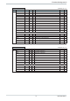
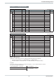
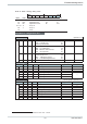

GPIDPar
(Funktions-Nr: 14)
Code Descr. Channel R/W Type Description Range Rem.
B2 Xp1 1 R/W INT Proportional band of channel 1
Tn1 1 R/W INT Integral time of channel 1
Tv1 1 R/W INT Derivative time of channel 1
T1 1 R/W INT min. cycle time of channel 1
Xp1 2 R/W INT Proportional band of channel 2
Tn1 2 R/W INT Integral time of channel 2
Tv1 2 R/W INT Derivative time of channel 2
T1 2 R/W INT min. cycle time of channel 2
...
Xp1 8 R/W INT Proportional band of channel 8
Tn1 8 R/W INT Integral time of channel 8
Tv1 8 R/W INT Derivative time of channel 8
T1 8 R/W INT min. cycle time of channel 8
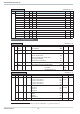
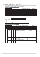
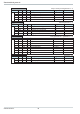
Parameter a. configuration data
General
(function no.: 0)
Code Descr. R/W Type Description Range Rem.
B3 71 C900
1)
COM1
R/W INT Prot: Protocol type
Baud: Baudrate
(T)
(H,Z)
0..xyy0
72 Adr1
1)
R/W INT COM1: Instrument address: 0..99
73 C904 R/W INT Freq: Mains frequency 50/60
Alm-Ver: Alarm version
Mode-out:Configuration-version of the
analog outputs (old/new)
Mode-out current zero 0/4 mA
(T)
(H)
(Z)
(E)
0..x000
74 C902
1)
COM2
R/W INT Prot: Protocol type
Baud: Baudrate (omitted with PROFIBUS)
(T)
(H,Z)
0..wxyz
75 Adr2
1)
R/W INT COM2: Instrument address: ISO1745 (def. 0)
CAN-BUS
PROFIBUS (def. 126)
0..99
0..255
0..126
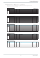
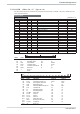
I/O connection
(function no.: 2)
Code Descr. R/W Type Description Range Rem.
B3 71 HC100 R/W FP Span end for HC 1...9999
72 C500 R/W INT Main configuration IN1/OUT13 ... IN4/OUT16
Fkt_dio1: IN1 / OUT13
Fkt_dio2: IN2 / OUT14
Fkt_dio3: IN3 / OUT15
Fkt_dio4: IN4 / OUT16
(T)
(H)
(Z)
(E)
0..wxyz
73 C530 R/W INT Main configuration OUT17 ... OUT19
mode_do17
mode_do18
mode_do19
(T)
(H)
(Z)
0...xyz0
74 C151 R/W INT Allocation HC/leakage current Alarm
DestHC
DestLeck
DestOutError
(T)
(H)
(Z)
0...xyz0
75 HCycl R/W INT Heating current cycle time 0...999
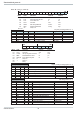
Function block protocol
9499 040 50511 32
1) Baudrate and address setting are effective only after initialization, e.g. protocol switch-over.