
Owner manual
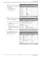

I/O connection
(function no.: 2)
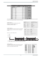
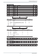
Code Descr. R/W Type Description Range Rem.
0 Block 1...2 R Block
1 State_alarm_out R ST1 Status alarm outputs
H
2 State_dio R ST1 Status digital inputs/outputs
I
20 Block 21...24 R Block
21 SnOEMOpt R INT Serialnumber OEM-Field
22 SnFabMonth R INT Serialnumber Produktion month
23 SnCntHi R INT Serialnumber Counter High
24 SncntLo R INT Serialnumber Counter Low
30 Block 31...33 R Block
31 Fdo1 R/W INT Forced digital outputs: OUT1 ... OUT8
J
32 Fdo2 R/W INT Forced digital outputs: OUT9 ... OUT16
K
33 Fdo3 R/W INT Forced digital outputs: OUT17 ... OUT19
L
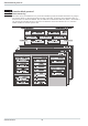
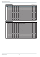
Rem. H State_alarm_out
MSB LSB
D7 D6 D5 D4 D3 D2 D1 D0
Bit no. Name Allocation Status ‘0’ Status ‘1’
D0
R1 Relay 1 off on
D1
R2 Relay 2 off on
D2
R3 Relay 3 off on
D3
do1_12 AL Alarm outputshort circuit OUT1 ... OUT12 off on
D4
HCscAL Alarm message heating current short circuit off on
D5
‘0’ always ‘0’
D6
‘1’ always ‘1’
D7
Parity
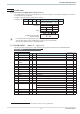
Rem. I State_dio
MSB LSB
D7 D6 D5 D4 D3 D2 D1 D0
Bit no. Name Allocation Status ‘0’ Status ‘1’
D0
Par_Nr Parameter set number set 0 set 1
D1
w/w2 w/w2 switch-over w w2
D2
Coff Controller off off on
D3
Leck Leakage current off on
D4
‘0’ always ‘0’
D5
do13_16f OUT13 ... OUT16 Fail no yes
D6
‘1’ always ‘1’
D7
Parity
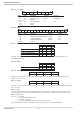
Rem. J Data structure
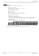
Bit 1514131211109876543210
Signification 00000000OUT8 OUT7 OUT6 OUT5 OUT4 OUT3 OUT2 OUT1
Rem. K Data structure
Bit 1514131211109876543210
Signification 00000 000OUT16 OUT15 OUT14 OUT13 OUT12 OUT11 OUT10 OUT9
Rem. L Data structure
Bit 1514131211109876543210
Signification 00000000 00000OUT19 OUT18 OUT17
Function block protocol
29 9499 040 50511