
Owner manual
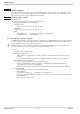

After taking the test set-up into operation, testing of the I/O area and parameter channel call-up are possible
by means of the graphic modules enclosed in the project.
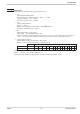
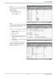
Graphic module 1:
Shows all process data of channel 1 (fix point).
Example: (specified set-point = 30)
Value 300 is written in AW 4.
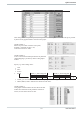
Graphic module 2:
Access to the function module parameters for parameter
channel mapping is possible by means of this graphic
module.
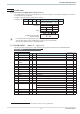
Specify e.g. when reading values:
w
Code
w
Fbno
w
FCTno
•
Setting
Specify “1" when reading with Specify ”1" when reading with
Integer Real Integer Real
00 00
w
ANZW gives the status and the result after completing the FB handling.
w
DWLR, DWLI, DWLC indicates the number of read values.
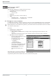
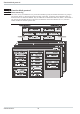
Graphic module 3:
This graphic module indicates the first data of the data
module into which data of the parameter channel are
written, or from which values are read.
Quick entrance
23 9499 040 50511
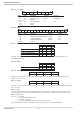
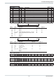
Operanden: Signalzustände:
-Unit_Sta EW 0 KM=00000000 00000000
-UnitCntA AW 0 KM=00000000 00000000
-UnitCntB AW 2 KM=00000000 00000000
-Xeff_1 EW 2 KF=+290
-Yeff_1 EW 4 KF=+400
-HC_1 EW 6 KF=+0
-Alarm_1 EB 8 KM=00001100
-Status_1 EB 9 KM=00010010
-Wvol_1 AW 4 KF=+300
-Yman_1 AW 6 KF=+400
-Cntrl_1 AW 8 KM=00000000 00000001
-DWLR MW 52 KF=+1
-DWLI MW 54 KF=+0
-DWLC MW 56 KF=+0
-Read/Wr MW 58 KH=0001
-Code MW 60 KF=+32
-FBno. MW 62 KF=+50
-FCTno. MW 64 KF=+1
-Type MW 66 KF=+0
-ANZW MW 68 KM=00000000 00000010
-Setting MB 0 KM=00000000
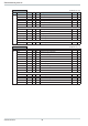
......... DB 12
-DBval1 DW 11 KF=+300
Operanden: Signalzustände: