
Owner manual

q
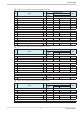
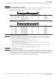
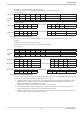
Module H (Multiplexing of all 64 variable processdata and parameterchannel)
No.. Descr. R/W
FIX Point-Format
Rem.
Number of
Bytes
Value
Hex COM PROFIBUS
Inputs ] 16
0 Unit_State, Digital_Outputs R 4 13 32DE
A, F
1
Index IN
Read
R 2 50 1AE
Write
2 Read Value R 2 50 1AE
Outputs ] 16
3 Unit_Cntrl I, Unit_Cntrl II W 4 23 32DA
B
4
Index OUT
Read
W 2 60 1AA
Write
5 Write Value W 2 60 1AA
In- /Outputs
6 Parameterchannel R/W 8 / 8 F3 4AX
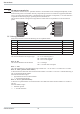
Operating principle (reading):
w
Enter the index number into ‘Index OUT’ (Read).
w
After the index number is mirror-inverted in ‘Index IN’ (Read), the read value is stored in
‘Read Value’ .
Operating principle (writing):
w
Enter the index number into ‘Index OUT’ (Write)
w
Enter the value to be written into ‘Write Value’.
w
After the index number is mirror-inverted in ‘Index IN’ (Write), the value was transmitted.
g
To ensure consistent data transmission, ‘Index OUT’ (Write) and ‘Write Value’ must have been updated
safely before a PROFIBUS data cycle. If this cannot be ensured, proceed as follows: ‘0’ in ‘Index OUT’
(Write), write the value to be transmitted into ‘Write Value’ and write the index number into ‘Index OUT’
(Write). With entry ‘0’ in ‘Index OUT’ (Read) / ‘Index OUT’ (Write), no data are transmitted.
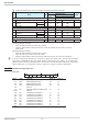
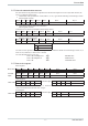
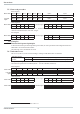
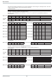
3.1 Defined as status byte are:
Unit_State
MSB LSB
D15 D14 D13 .. .. D2 D1 D0
Bit no. Name Allocation Status ‘0’ Status ‘1’
D0
IN13 Digital input IN13 (ParNo) off on
D1
IN14 Digital input IN14 (Coff) off on
D2
IN15 Digital input IN15 (Leck) off on
D3
IN16 Digital input IN16 (w/w2) off on
D4
always ‘0’
D5
Dex Changed ComRead or ComWrite data no yes
D6, D7
Always ‘0’
D8
Err1 Transmission error channel 1 no yes
D9
Err2 Transmission error channel 2 no yes
D10
Err3 Transmission error channel 3 no yes
D11
Err4 Transmission error channel 4 no yes
D12
Err5 Transmission error channel 5 no yes
D13
Err6 Transmission error channel 6 no yes
D14
Err7 Transmission error channel 7 no yes
D15
Err8 Transmission error channel 8 no yes
Process data
9499 040 50511 12